HAL Id: hal-01676643
https://hal.archives-ouvertes.fr/hal-01676643
Submitted on 10 Jan 2018HAL is a multi-disciplinary open access archive for the deposit and dissemination of sci-entific research documents, whether they are pub-lished or not. The documents may come from teaching and research institutions in France or abroad, or from public or private research centers.
L’archive ouverte pluridisciplinaire HAL, est destinée au dépôt et à la diffusion de documents scientifiques de niveau recherche, publiés ou non, émanant des établissements d’enseignement et de recherche français ou étrangers, des laboratoires publics ou privés.
Disassembly task evaluation by muscle fatigue
estimation in a virtual reality environment
Jingtao Chen, Peter Mitrouchev, Sabine Coquillart, Franck Quaine
To cite this version:
Jingtao Chen, Peter Mitrouchev, Sabine Coquillart, Franck Quaine. Disassembly task evaluation by muscle fatigue estimation in a virtual reality environment. International Journal of Advanced Manufacturing Technology, Springer Verlag, 2017, 88 (5-8), pp.1523-1533. �10.1007/s00170-016-8827-6�. �hal-01676643�
1
Disassembly task evaluation by muscle fatigue estimation in Virtual
reality environment
Jingtao Chen°,°°,°°°1, Peter Mitrouchev°, Franck Quaine°°, Sabine Coquillart°°° ° Univ. Grenoble Alpes, G-SCOP, F-38000, Grenoble, France
CNRS, G-SCOP, F-38000 Grenoble, France
°° Univ. Grenoble Alpes, GIPSA-Lab, F-38000, Grenoble, France
CNRS, GIPSA-Lab, F-38000 Grenoble, France
°°° INRIA –LIG Montbonnot, F-38334, Saint-Ismier, France
Abstract Today disassembly operations play a very important role during the initial design phase of industrial products considering the role played by these operations throughout the Product Life-Cycle (PLC). The available disassembly evaluation methods seldom make disassembly as the preferred end-of-life solution for the reuse of parts or components in an economically sustainable way. This paper deals with a new method for disassembly sequences evaluation by muscle fatigue and metabolic energy expenditure estimation. It is based on four hypothesizes for building the equivalence between the metabolic energy expenditure of the human arm during disassembly operation simulation and corresponding muscle fatigue developed in the operator’s arm muscles. For this purpose, the mechanical energy expenditure on operator’s arm is involved to evaluate the possible disassembly sequences. The proposed method is validated by a set of experimental tests performed in a Virtual Reality environment. The results of the analysis and findings show that the mechanical energy expenditure can be used to evaluate the disassembly sequence by considering the human muscle fatigue factor while performing disassembly operation simulation.
Keywords Disassembly sequences evaluation; Muscle metabolic energy; Mechanical energy; Muscle fatigue; Virtual Reality Environment
1. Introduction
1 Corresponding author. phone +33 (0)4 76 57 43 95, Fax. +33 (0)4 76 57 46 95 E-mail: [email protected]
2
Simulations closely related with Assembly/Disassembly (A/D) operations represent important research subject today. These A/D operations are often considered in the initial stage of product design. Literature reports many methods for analysis and different simulation applications which use information referring to components mating.
Nowadays, Virtual reality (VR) environments have significantly evolved towards A/D simulations, highlighting new needs for A/D simulation preparation, evaluation and their integration in Product Development Process (PDP) [1–6]. All these simulations address different objectives such as: A/D sequencing, path planning, collision detection, operational time, amongst others. Note that these objectives are often complementary to each other. In order to evaluate assembly sequences and product maintenance process, different tools and novel VR human-computer interfaces are proposed [7, 8]. Thus, VR is a new technology that creates a real-time visual/audio/haptic experience with computer systems and provides a potential way for disassembly operation simulation [9]. Most of the recent works on A/D related with VR technology focus on the simulation itself. They try to build an environment to assemble/disassemble products and compare the simulation results with those of a real A/D process. In this context, Aleotti and Caselli [10], proposed a physics-based VR environment (VRE) for task learning and intelligent disassembly planning. Ladeveze [11] proposed an interactive path planning method for haptic assistance in assembly task. Gomes [8] used VR technology as a tool for verification of assembly operations and maintenance processes. Many of these platforms use haptic feedback and are facing difficulties while simulating insertion/extraction operations realised by the forces of human muscles and the induced fatigue.
The literature search carried out within the framework of our recent work shown that certain existing approaches for disassembly evaluation some integrated in VRE were proposed by taking into account of different criteria such as: visibility score, set of directions for removal (SDR), stability of sub-assembly, disassembly time, [10, 12–16]. However, they do not take into account of the muscle fatigue of the operator for varied conditions of requests (postures, efforts), which in our opinion is very important today with the increasing of the retire age of the operators.
The increasing complexity of operations during maintenance, repairing or recycling of products dramatically raises the difficulties of disassembly sequence decision. A/D process represents generally almost 30 % of the product cost. Therefore, realistic A/D process evaluation can improve efficiency and reduce cost.
Thus, preliminary evaluation of disassembly sequences during product design is a very important issue. For disassembly task of complex products, two questions are arising, namely: disassembly sequence generation and their evaluation. This paper is focusing on the second one. VREs which combine haptic device with force feedback and 3D projection technology are appropriated tools to simulate, evaluate and validate A/D process of the product in the design phase. They are also helpful aid for disassembly task training [17].
3
becoming more globalized. Their purpose is to try to fit the task to the human not the human to the task [18]. The key point for an effective application is to gain a balance between the human body capacities and the task demands [14].
A method to evaluate the quality of disassembly sequences by choosing the optimal one is presented in [19]. It is based on a cost function which calculates the cost value of each disassembly sequence. The cost value itself is the sum of two values (coefficients) given by the user: w1 reorientation and w2 parts. However, due
to lack of unified units between reorientations and parts, the calculated cost value do not rigorously evaluate the quality of the possible sequences.
Tseng and Huang [20] used particle swarm optimization method to evaluate A/D sequences. A cost function which considers: operation cost, stability cost, accessibility
cost, tool setup cost and weight effect cost is proposed by the authors. It considers
the disassembly direction as one of evaluating criteria but ignores how many displacements are generated on a given disassembly direction.
Jayaram [21] proposed to integrate RULA (Rapid Upper Limb Assessment) algorithm [22] into a VRE for real time and continuous ergonomic evaluation. RULA algorithm is based on some criteria such as: posture, weight of loads, task’s duration and frequency of pauses taken by the operator while performing a given task. The method assigns a score to assess the risk of upper limb injury while performing A/D operation. However, the muscle fatigue is not taken into account in the assessment.
Srinivasan [23] proposed also a disassembly cost function for disassembly sequences evaluation. For this purpose, parameters such as: removing time of
component and fasteners, accessibility and orientation factors, and disassembly distances are proposed. However, similar with the drawbacks of [13, 20, 21], simply
multiplying or dividing a subjective weight value with a factor being considered in disassembly operation does not promise to obtain a convincing analytical model with corresponding physical essence.
A method for ergonomic disassembly sequences evaluation was presented also in [24]. Four ergonomic factors for disassembly sequence evaluation are proposed, namely: disassembly instruction availability, complexity of disassembly task, special
hand maneuvering factor and visibility of part. However, it does not consider
operator’s muscle fatigue which, in our opinion, is highly influencing work’s efficiency.
The total time for disassembly was proposed as main evaluation indicator for disassembly operations’ evaluation in [12, 25, 26] by considering the disassembly direction and the joint type. However, using the total time for disassembly is not an appropriate indicator because the operator may expend different amount of energy for moving the same component with different velocities, i.e. with different power. Lacking of considering this problem, disassembly total time is one independent factor in the evaluation model. Cappelli et al. [27] presented a method for disassembly operation evaluation based on genetic algorithm and integrated in a VRE. They proposed two indicators which are: disassembly time and cost. However, the method is not completely defined because it does not allocate weight values to each disassembly indicator which limits its efficiency.
4
Trying to avoid uncertainty of disassembly operation process, Tian et al. [28] proposed a method to calculate the probability of disassembly energy's distribution and the minimal energy expenditure in a disassembly sequence. The minimal energy for each disassembly sequence is estimated. However, the authors point out that the probable energy expenditure intervals of several disassembly sequences have the possibility to overlap with each other. In this context, a new method is needed for choosing the less-energy-spending disassembly sequence.
In order to consider some factors related to human being, Desai and Mital [29] subdivided disassembly operation into several elementary tasks and subjectively allocated values to each of them. The method combines both disassembly sequence generation and evaluation. However, the proof for the reasonability of the allocated subjective values is lacking, thus discrediting the reliability of the proposed method. Recently a new method for disassembly sequences evaluation was proposed by Wang et al. in [14]. Integrated in a VRE, the method is based on five criteria which are: visibility of a part, disassembly angles, number of tools’ changes, path
orientation changing and sub-assembly stability. All five criteria are presented by
automatically calculated dimensionless coefficients, thus allowing the evaluation of the complexity of disassembly sequences. However, the method does not take into account the physiological stat of the operator, such as muscle fatigue. A method for selective disassembly planning and evaluation based also on particle swarm optimization was proposed by Li [30]. However, there are no criteria related with human fatigue in the proposed disassembly sequence evaluation process.
In order to model work-recovery ratios for optimizing the recovery time during tasks, Rose et al. [31] presented data from empirical study regarding how maximal pushing force, endurance time, resumption time and perceived discomfort vary with loading level and loading time. During the tests, subjects were asked to perform two trials which each of them includes a loading and recovery trial. The results of the experiments show that: i). shorter endurance time is found in high loading level, compared with low loading level; ii). subjectively perceived discomfort increases linearly with the increase of loading level; iii). the resumption time does not monotonically vary with loading levels. However, this work does not present a general model allowing to describe the working-recovery ratios.
Some bio-mathematical models of fatigue (BMMF) based on work hours data have been proposed in [32] to predict the levels of fatigue associated with a pattern of work. Fatigue Audit Inter Dyne (FAID) is one of the BMMFs which has been commercially used to estimate the work related fatigue. The hours of work are the input in the model allowing to estimate the work related fatigue associated with shift workers’ duty schedules [33]. The output fatigue score represents a predicted sleep opportunity. One of the benefits of FAID model is the good availability of hours of work, which is the input data, in the organizational records.
Predicting metabolic energy assumption associated with a disassembly sequence can be a method for evaluating the fatigue level induced by each disassembly
5
sequence. In this optic Bisi [34] proposed an EMG (Electromyography2) driven model for predicting metabolic energy consumption during physical effort. It includes EMG signals from active muscles associated with kinematic joint parameters. However, the model is too complex to be applied in the disassembly operation evaluation.
After reviewing some current approaches for disassembly evaluation, some of which were presented here above, it should be noted that current simulation platforms do not offer the necessary information and versatility required for a complete A/D process simulation, including human/operator data management based on physiologic data (EMG signal for instance). The functional constraints associated to human biomechanics are not taken into account either, and particularly the energy expenditure for achieving manipulations while performing A/D operations. Information about the muscle exhaustion of the operator is not included in the A/D simulations either. Thus, there is a strong need to evaluate disassembly operation by considering muscle fatigue of the operator.
Note that muscle fatigue is an important factor which can affect the efficiency of the task execution. The level of fatigue can be estimated by calculating the decreasing slope of median frequency of EMG signals [35]. Those signals are detected on chosen points on the human arm muscles when the operator is performing a task. Thus, all EMG signals should be filtered by the pass band between
20Hz and 500Hz which is the main range of EMG signals. The more the slope of
median frequency decreases, the more muscle fatigue there is [36]. The peak value of EMG signals after root mean square (RMS) processing is also an index of fatigue [37] when subjects are performing the task at the same level of force. However, asking operator to actually perform all the possible disassembly sequences and off-line recording the EMG signals may cost much time, especially in the case of disassembly sequences for relatively complex assemblies. Hence, another method of predicting the fatigue during disassembly operation should be proposed to achieve the evaluation of disassembly process in VRE. As we are aware, in the literature there are not methods involving muscle fatigue to evaluate disassembly sequences.
In this context this paper focuses on considering the operator’s muscle fatigue factor in disassembly task evaluation. Thus, a new method for evaluating the disassembly sequence by utilizing metabolic energy expenditure is proposed here.
The two principal parameters for carrying out the calculation of metabolic energy expenditure for each disassembly sequence are the weights and the
disassembly paths of the components. For this purpose disassembly experiences in
VRE were performed in order to evaluate fatigue with EMG during disassembly operations simulation.
This work is a preliminary phase of our ongoing research showing that using EMG data can give relevant information about the subject muscle state, which could be of interest in the field of evaluation of disassembly operations. The proposed method aims to choose the disassembly sequence which induces less muscle fatigue.
The results of this study may be useful to designers and production managers as
6
decision making tool allowing them to decide which disassembly sequence among all the possible ones induces least fatigue of the muscles thus improving the PDP. The rest of the paper is organized as follow: Section 2 presents the method for evaluating the mechanical work during component disassembling, and the proof and explanations for the proposed hypothesizes upon which the method is based. The metabolic energy expenditure estimation for disassembly sequences operation evaluation is presented in this section as well. At the end of section 2, how to use the proposed method to perform the muscle fatigue estimation for possible disassembly sequences is explained via an example. In section 3, experiments of simple disassembly task performed in VRE are presented. The muscle fatigue is estimated by treating EMG signals collected from the arm muscles of the involved subjects. The experimental results are compared and show a very good correlation with the theoretical results calculated by the proposed mechanical model. Finally conclusions and future work are suggested in Section 4.
2. Proposed method
The method for disassembly task evaluation proposed here is based on metabolic energy expenditure estimation model.
2.1 Hypotheses and basic principles
Considering muscle fatigue factor in disassembly task evaluation, the disassembly sequence which induces less muscle fatigue should be chosen. In VRE with force feedback device, the arm is the principal energy consuming part of the human body. Therefore, this paper focuses on the evaluation of the muscle fatigue on the arm. For this purpose the arm’s energy expenditure is used as indicator for muscle fatigue estimation. The method presented here below is built upon the following hypotheses:
Hypothesis 1: The More mechanical energy is required to complete the disassembly task, the more metabolic energy will be consumed in the human arm.
Hypothesis 2: The arm muscles, involved in the disassembly task, perform in an environment with constant temperature. The task is performed in continue way, so muscles do not have time to rest. The fatigue accumulated in the muscle is a monotonically increasing function of the metabolic energy expenditure.
Hypothesis 3: During the disassembly task, the operator is moving the components with a constant velocity in all allowed disassembly directions. The disassembly trajectory (path) is not a closed loop.
Hypothesis 4: Under the condition of Hypotheses 1, 2 and 3, if the consumed metabolic energy for performing disassembly task (sequence) 1 is bigger than this for disassembly task (sequence) 2, then disassembly task 1 induces more fatigue than 2. The reason why the hypothesis 1 cannot be obviously established is that the mechanical work is only a part of the energy consumed in the arm. Exerting force to
7
move a component is not the only part that consumes the muscle metabolic energy. Let (in Jules/kg) be the total energy expenditure rate for a muscle. It can be expressed as following [38]:
(1)
where: is the muscle activation heat rate, is the maintenance heat rate,
is the shortening/lengthening heat rate and the mechanical energy rate. By
multiplying with the mass of the muscle, the mechanical work expenditure can
be obtained. The relationship between the increase of and the variations of
is not evident. Thus, hypothesis 1 is proposed, and its proof is presented in the next.
2.1.1 Proof for hypothesis 1
Let is the percentage of mechanical energy expenditure. Then one has:
(2)
Let . It is easy to prove that is a monotonically decreasing function of .
However, the experiment results presented in [39] indicate that is a monotonically decreasing function of . Then it can be proved that is a
monotonically increasing function of (
). Since
is equivalent with , consequently is also a monotonically increasing function of . Thus, is a monotonically increasing
function of .
2.1.2 Proof of hypothesis 2
According to the conclusions in [40, 41] it is stated that: i).The level and duration time of exerted tension vary with the changes of the successive contractions and the external temperature (in [41], the muscles are immersed in water on two places with different temperatures); ii). The durations of muscle’s contraction in 18℃ are much greater than ones in 34℃.Based on those two statements, duration time between two contractions is set to zero and the ambient temperature is fixed while performing disassembly operation.
According to Hypothesis 2, the fatigue accumulated in the muscle is a monotonically increasing function of the metabolic energy expenditure. In addition,
8
according to the conclusions in [42], the force generation capacity after the exercise is monotonically decreasing with the increase of force level and consequently can be used as an index of fatigue level estimation. Thus, we may do the hypothesis that the fatigue accumulated in the muscle is monotonically increasing with the increasing force level. A consequence of Hypothesis 1 is that the mechanical energy will monotonically increase with the increase of force level. The results in [31] clearly concluded that higher load level leads to statistically significant shorter endurance time and resumption time increases with increasing loading time. Both shorter endurance time and longer resumption time indicate the accumulation of more fatigue. We express the fatigue FA as the function: , where F is the loading level; t loading time, v moving velocity and OP other parameters involved in the task. If the metabolic energy expenditure E is considered as a function of F, t and v, then the FA can be expressed as: . The FA derivative of F is: . Thus, based on the data presented in [31], the FA is a monotonically increasing function of F, which means that . It is obvious that
and consequently
is correct in the range of loading level tested in
[31] which are in agreement with those observed in disassembly operations. It means that FA is a monotonically increasing function of E.
2.2 Mechanical work for performing disassembly sequence
A repeatedly performed training for a long time may activate the neural adaption of muscles and their activation mode may change after training. In this optic, Rube and Secher [43] performed leg task experiment in three phases. During the first one all subjects were asked to perform one hundred and fifty MVCs (maximum voluntary contractions) in isometric leg extension task. On the second phase, subjects were signed into two groups: one performing a training task with one-leg, the other performing the same training with two-legs. During five weeks, one-leg and two-legs training have been respectively performed by each group. After training, both groups were asked to perform once again one hundred and fifty MVCs in isometric one- and two- legged extension task, which was the third phase of the experiment. The results of comparison between the MVCs values before and after training shown that one-legged group of subjects was less tired when performing one-legged task, and two-legged group was less tired during two-legged task. In [44], it is mentioned that the effect of training on fatigue depends on training mode. For a disassembly sequence, the loading level, loading time and operation posture of each task are not always the same. That is the reason why the effect of long-time task training on fatigue is considered in here.
Based on the proof for Hypothesis 1 (Section 2.1.1), if the mechanical work consumed to perform the disassembly task (sequence) can be calculate, it can indicate which disassembly task consumes more metabolic energy and consequently
9 induces more fatigue in the muscles.
In disassembly operation, the two principally involved tasks are fasteners’ disassembling and components’ moving. In the following content of this section, the mechanical energy expenditure for moving disassembly component and operator’s arm are respectively presented.
2.2.1 Mechanical energy expenditure for moving disassembly components
The mechanical work spent by the muscular force required to perform the task (moving an object/component) will transfer into potential and kinetic energies. Suppose that the -th component should be disassembled in disassembly sequence (task) 1, the variation of the total mechanical energy is:
(3) where: and are respectively the variations of kinetic and potential
energy, is the mass of the component, and are respectively the velocity
of the component at ending point and starting point, and is the vertical displacement of the component. The system is evolving in Earth gravity field (gravity vector g is supposed in negative vertical direction). Let and be respectively
the total vertical displacement of the mass center of the th disassembled (handled) component along the positive (up) and negative (down) directions. The velocities and are both equal to 0 m/s, then equation (3) can be written as:
(4) Consider the handled component as an isolated system, and let and
be respectively the variation of mechanical energy when the component moves upward and downward:
(5) (6) Although and have opposite signs, they cannot offset with each
other when calculating the mechanical energy expenditure of the arm. If the component is only affected by the gravity, the variation of its potential energy should be equal to the variation of the kinematic energy. But when the component is stopping at a highest or lowest point of the disassembly path, the kinetic energy is zero, which corresponds to the starting point of the disassembly path. The reason why the potential energy does not fully transform into kinetic energy is because of the mechanical work done by the arm. Hence, for disassembling the th component, the mechanical work done by the arm is:
(7)
10
The variation of mechanical energy of operator’s arm from the starting point of the th component to the position of the next handled (disassembled) component, , can be express as:
(8)
where: is the mass of the arm, is the vertical displacement of the mass
center of the arm between the starting point of the th component and the position of the next component; and are respectively the variation of the
kinetic and potential energies of operator’s arm. Similarly as the mechanical energy of the disassembly component (eq. 7), can be written as:
(9)
where: and are respectively the total vertical displacement of the arm’s
mass center along the positive and negative direction of th component. The mechanical work done by the shoulder to move the arm is:
(10)
Assuming that there are n components to be disassembled in task S (disassembly sequence S), the required arm’s mechanical energy is:
(11) When the operator’s arm is coming back to the initial position after performing the task (disassembly sequence): . Thus, equation (7) can be rewritten as:
(12) Note that and should be the real vertical displacement of the end point of
the hand in the real world, not the vertical displacement of avatar hand in the VR world (see details in Section 3.2).
2.2.3 Vertical displacement of the arm’s mass center
The vertical displacement of the center of the arm’s mass (see eq. (12)) is
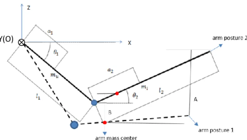
also a parameter, which has to be calculated. The arm can be geometrically abstracted as a two DOF (degrees of freedom) mechanism with three segments as shown in Fig.1. Note that the first segment is the operator’s body, supposed to be the frame.
11
Fig. 1 Arm and its associated two joints mechanism
Assume that the shoulder only rotates around Y axis. Consequently the forearm and upper arm form the plane of ZOX. Let: and be respectively the length of upper and lower arms; and the relative position of mass center of upper and lower arms; and respectively the mass of the upper and lower arm; and and the absolute rotation angles of each segment (upper and lower arms) related to the horizontal frame axe X. It is assumed that the center of mass of each segment is stable inside each segment. Thus, the coordinates x and z of arm’s mass center can be expressed as:
(13)
(14) For a given disassembly path of the th component, the vertical displacement of the hand end point between two dates and is:
(15) The vertical displacement of the arm’s mass center is:
(16)
Let and . Then, can be expressed
as function of and ( being eliminated):
(17)
12
The relation between and implies that the rotation angle of upper arm
in ZOX plane at the starting and ending point of the trajectory of the th
component has to be measured. From eq. (17), can be expressed as:
(18)
where: .
Finally, Ai can be calculated from the disassembly path of the th component.
2.2.4 Mechanical energy expenditure for fasteners’ disassembling
For disassembling fasteners, two types of manipulations may occur in the work environment: manually disassembling or using appropriated tools. Disassembly operation management is often related with structurally complex and large products (assemblies). In this case, it is reasonable to suppose that the disassembly of fasteners will be performed mainly by using special disassembly tools. Consequently, these tools can be considered as normal disassembly components moved (handled) by the operator during the disassembly process. Hence, calculation energy expenditure for disassembling fasteners is performed by using the same model as for the disassembly components.
Thus, with the proposed model, the mechanical energy expenditure on performing all the possible disassembly sequences (including moving the disassembly components and fasteners) can be estimated by equations (12) and (18). 2.3 Example of calculation
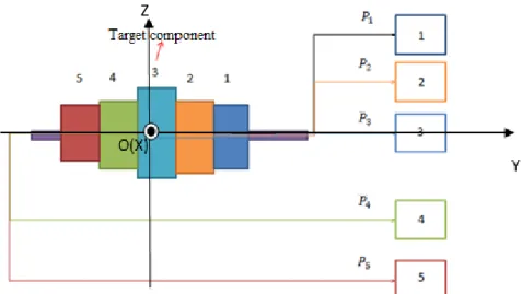
In order to illustrate the model for evaluating the fatigue induced during disassembly sequence simulation, an example of mechanical assembly with five components (parts is presented here below. Let the target component be component 3 as presented in Figure 2.
13
Fig. 2 Mechanical assembly and parts’ trajectories
Legend: 1, 2…5 unload area for each component, Pj disassembly path (trajectory) of th component
There are two possible disassembly sequences for disassembling the target component : Sequence S1={1,2,3} and Sequence S2={5,4,3}. In here,
and denote respectively the disassembly starting point and
disassembly ending point coordinates of the mass center of th component. The values of the three parameters, namely: mass and its starting and ending positions of each component are presented in Table 1.
Table 1 Parameters for disassembly sequence evaluation
Mass Value (kg) Starting point Value (m) Ending point Value (m) 1 (0,0.2,0) (0,0.6,0.6)
1.5 (0,0.1,0) (0,0.6,0.3)
3 (0,0,0) (0,0.6,0)
1.8 (0,-0.1,0) (0,0.6,-0.2)
0.8 (0,-0.2,0) (0,0.6,-0.4)
As previously said, the proposed method for evaluating the disassembly task by mechanical energy expenditure requires to measure angle of the arm at the starting and ending point for all the components involved in the disassembly sequences. Kinect 2 was used to measure this angle and the data are as presented in Table 2.
Table 2. Angle between operator upper arm and horizontal frame line for starting and ending point of the components
Component 1 2 3 4 5 Z
14
(rad)
-0.550 -0.592 -0.627 -0.592 -0.550
(rad)
0.500 0.159 -0.387 -0.429 -0.953
Concerning the parameters of the arm, they are the same as in [45] presented in Table 3.
Table 3. Parameters of the arm
(kg) (kg) (m) (m) (m) (m) values 2.537 2.332 0.298 0.419 0.151 0.167
The values of for each component, calculated according to equation (18)
are presented in Table 4.
Table 4. Values of
component 1 2 3 4 5
(m) 0.223 0.0837 0.025 0.006 0.158
According to the proposed model, the mechanical energy for performing the disassembly Sequence 1 and Sequence 2 are respectively:ES1 41.87J and
J ES2 24.66
. It is seen that ES1 is bigger than ES2. Based on Hypothesis 1, 2,
3 and 4, the results show that performing disassembly Sequence 1 induces more fatigue in the arm’s muscles than disassembly Sequence 2.
3. Experimental disassembly sequences evaluation by muscle fatigue estimation
3.1 Experiments
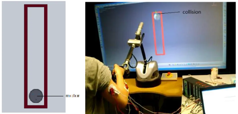
In order to prove the proposed method, series of experiments were carried out in a Virtual Reality environment. The task consisted in handling an electrical motor (weight of 1kg.) in a restricted vertical space of 0.5m with repetitive bottom up and
up down movement during 5 minutes with a frequency of 25Hz.
According the Hypothesis 1, 2 and 3, subjects were asked to perform continuous movements during 5 minutes in order to avoid the muscle of resting. The visual feet-back (displacement of the component in the VRE screen) is the same as the displacement of the end of the hand in the real physical environment. During the operation, the upper arm of subject is in static position ( is constant).
15
Nine subjects (eight male right-handed and one female left-handed), aged from 24 to 58, were involved in the experiments. Unfortunately the female subject did not endure until the end of the task, so the effect of different sex on fatigue have not been investigated in this stage of the study.
Subjects declared no performed intensive muscle efforts during 24 hours period. All participants reported no history of problem in upper limbs. Since is constant, when calculating the mechanical work, the task is performed when only the lower arm is moving.
3.1.2 Simulation tests
The tests were performed in the Virtual reality environment in GINOVA Lab at Grenoble INP (National Polytechnic Institute). The environment consists of (Fig. 3): VIRTUOSE 6D35-45 haptic device with force feedback, Kinect 2 tracking system, stereoscopic screen, 3D glasses and four channels EMG BIOPAC MP150 system.
The software used to generate the simulation environment is IFC (Interactive Fitting for CATIA) which is a CAAV5-based plug-in for CATIA V5TM for interactive simulations. It consists in two sets of V5 commands, appearing as two new toolbars: i). IFC core which provides tools for creating an interactive physic simulation session, managing interaction devices, changing object properties, etc.; ii). IFC human complements which is a IFC Core with human simulation functionalities, such as: calibration, grasping, etc. The toolbar used here is IFC Core. The mass and the weight of the component can be set and the gravity environment can be simulated. Virtual object in the software are constrained by gravity field. The force feedback, during collisions, is sent to the haptic device.
Fig. 3 Virtual reality experimental environment
The task was divided into two sub tasks in order to discriminate which one induces more muscle fatigue. The first 2.5 minutes period represents the task 1 (T1). The total 5 minutes period represents the task 2 (T2).
16
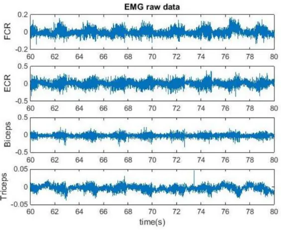
During the task (subjects in standing position), the EMG signals for the four sets of electrodes of EMG BioPac MP150 system were recorded according to SENIAM (surface EMG for non-invasive assessment of muscles) location protocol. The muscles involved were: extensor carpi radialis (ECR), flexor carpi radialis (FCR), biceps and triceps. The signal from the electrode on the ulnar styloid process muscle was used as ground signal.
The EMG signals for each subject have been normalized with EMG signals of each muscle detected during the task.
After filtering, Fast Fourier Transfer (FFT) function was used to transfer the raw EMG signal. The power spectrum density of each muscle contraction was estimated by using Hamming window. The median frequency for each muscle contraction was approximated by straight line. Thus, bigger decreasing slope represents faster fatigue process.
3.2 Results
Figure 4 shows a typical EMG raw data recorded for a 20 seconds period of 5 minutes task.
Fig. 4 EMG raw data
The results after RMS processing are presented in Figure 5. Symbols A, B and C respectively represent the average peak value of five successive muscles’ contractions at the beginning of the task (A), at the end of task 1 (B) and at the end
17
of task 2 (C). Statistical analysis (unilateral Student t test, ) shows that a significant difference appears between C and B for FCR and Biceps muscles only (respectively t=-1.848, t=-1.775). No statistical difference was found in ECR and
Triceps muscles. The results indicate that T2 induces more fatigue than T1. It means
that the task involves greatly flexor muscles (FCR, Biceps) with greater fatigue in T2 than T1 for those two muscles. Table 5 shows the results of median frequency for
FCR and Biceps muscles. It confirms that fatigue appears in both of muscles.
Moreover, slope values indicate that fatigue increases faster in T1 than in T2.
Fig. 5 Average of last five successive peak values of NEMG signal of eight subjects for T1 and T2 after RMS processing (A, B and C are respectively the first muscle contraction, the average value of last five successive muscle contractions of T1 and
the average value of last five successive muscle contractions of T2). ( * indicates
statistical difference and n.s indicates no significant difference)
Table 5. Decreasing slope of median frequency of EMG T1 (2.5 minutes) T2 (5 minutes) FCR -0,13003878 -0,06598795 BICEPS -0,03164797 -0,0023069 3.3 Discussion
The results of the performed VRE experiments show that the Biceps and FCR muscles are the prime movers involved in the task. On the other hand, fatigue develops faster in T1 than in T2. This could be resulted from the fact that the
0 0,1 0,2 0,3 0,4 0,5 0,6
N
or
m
aliz
ed
EMG
A B C A B C A B C A B CFCR ECR BICEPS TRICEPS
18
anaerobic exercise of fast twitch is the activity mainly involved in the T1 task and the aerobic exercise of slow twitch is the principle muscle behavior in T2 task. The experimental results indicate also that there is greater fatigue in T2 than in T1.
In order to prove the validity of the proposed mechanical model (see Section 2.3), it was applied to calculate the mechanical energy expenditure in T1 and T2 performed in the VRE. The values of the mechanical energy expenditure are respectively and . Thus, according to the proposed
methodology, the fatigue developed in T2 is bigger than in T1, which is in agreement with the experimental results.
Assuming is a differential equation for calculating the fatigue (see Section 2.1.2), the maximal F with a given S or the maximal S with a given F can be the boundary conditions for solving this equation. In this case its solutions, based on the different boundary conditions, can be different. Note that purchasing the fatigue calculation formula and accurate fatigue value associated with specific tasks is not the aim of this paper. Instead, the mechanical energy expenditure has been used as an index to compare levels of fatigue induced while performing different tasks.
The proposed model for fatigue estimation, based on mechanical energy expenditure model, has analytical formulation and consequently is not concerned by the problem of how the boundary conditions influence fatigue.
In order to compare fatigue for different tasks, the associated mechanical energy expenditure values of disassembly operations are calculated here by the proposed mechanical model (equation (12) and (18)).
From the aspect of loading level, since the gravity force of the component was simulated in the VRE, it is the same as in the real world. From the aspect of operation method of haptic device, it only allows simulating a single hand operation by holding the handler of the VIRTUOSE haptic device. We agree that this is different with a real A/D process where two hands operations are often involved.
The main application field of the results of this study is to enable the disassembly operation manager to compare the fatigue levels associated with different disassembly sequences while performing disassembly tasks. Note that the difficulties of including physiological parameters and building complete skeletal-muscle model makes it very difficult to achieve the accurate calculation of fatigue level associated with a specific disassembly task. The difference in the individual physiological parameters also blocks the generalization of the model. Instead, the calculation of the mechanical energy expenditure here proposed is relatively simpler.
For the calculation of mechanical energy expenditure, the required parameters are components mass, the starting and ending position of the components and angle between operator upper arm and horizontal frame line for starting and ending position of the components. For a given disassembly sequence, the first two parameters are easily obtained. If the positions of operator and component are known, angle can be calculated. For evaluating the fatigue levels for different disassembly sequences, the proposed model is better than BMMF model and models based on skeletal-muscle properties. Thus, the proposed method may help to satisfy
19 the required accuracy in engineering applications.
There are two reasons for explaining why more real and complex mechanical assembly, which could generate more realistic disassembly sequence, have not been employed here. The first reason is that in order to induce the fatigue in arm muscles, enough exercise should be performed. Pre-tests have shown that if subject is repetitively moving a component between two points with vertical displacement and with a given frequency, he/she will feel fatigue at least after performing task for a short period time which is equivalent to really disassemble lot of components. Moreover, loading the mechanical assembly with this amount of movable components to create a simulation will cost an unpredictably long time. Instead, a basic task, consisting in manipulating of only one component with sufficiently long trajectory and execution time could be much easier to perform. It also avoids to be effected by the factor of subjects’ lacking of experience in haptic device manipulation. Another reason is that this simple task is easy to perform by subjects and allows controlling the velocity of task execution according to Hypothesis 3. 4. Conclusion and future work
Some limitations of the available techniques for disassembly operation simulations stimulated this research on disassembly operation evaluation. This paper introduces a new method for disassembly task evaluation which aims at using the expenditure volume of metabolic energy to quantify fatiguing disassembly task.
Thus, instead of the ergonomics simulation (RULA algorithm), it introduces a new source of performing disassembling task in a VRE. Comparing with the method proposed in [28], the method proposed here has clear formulation allowing to estimate fatigue induced during different tasks (operations of disassembly sequences for instance). The direct quantitative comparison of physical fatigue level induced during the different tasks execution is available without probability distribution and probable energy expenditure. The proposed method is also more efficient than the method of Bisi [34] which requires so much data necessary for predicting metabolic energy consumption and consequently fatigue evaluation. Thus, in order to improve the efficiency of disassembly task evaluation, a new method including muscle fatigue of the operator while performing disassembly tasks in VRE was proposed here.
The method is based upon four hypothesizes and proved by experimental tests. Thus, Hypothesis 1 has been proved from the theoretical derivation and experiment results.
The agreement between the theoretically calculated results and experiment ones indicated that the proposed method is pertinent for estimating the level of fatigue induced while performing a disassembly task in VRE. The analysis of the median frequency of EMG signals proved the existence of fatigue in the involved muscles. Another interesting result is that subjects fatigue happens faster in T1 (beginning of the task) than in T2.
One of the parameters appearing in the proposed mechanical model is angle which had to be measured. In future work, instead of using Kinect to measure this
20
angle, a geometrical model for its calculation should be built.
Acknowledgment: This work has been partially supported by the LabEx PERSYVAL-Lab (ANR--11-LABX-0025) » (http://www.persyval-lab.org/index.html)
References
1. Jung B (2003) Task-Level Assembly Modeling in Virtual Environments. In: Kumar V, Gavrilova ML, Tan CJK, L’Ecuyer P (eds) Comput. Sci. Its Appl. — ICCSA 2003. Springer Berlin Heidelberg, pp 721–730
2. Garbaya S, Zaldivar-Colado U (2007) The Affect of Contact Force Sensations on User Performance in Virtual Assembly Tasks. Virtual Real 11:287–299
3. Ashvinikumar P., Dibakar S. (2009) Haptics Aided Kinematic Assembly Modeling and Efficient Determination of Joint Ranges of Motion. 14th Natl. Conf. Mach. Mech. NaCoMM09 NIT Durgapur India
4. Luis M., Norman M., Terrence F. (2003) A constraint manager to support virtual maintainability. Comput Graph 27:19–26
5. Mohd F.F.R, Windo H., Ashutosh T. (2011) A review on assembly sequence planning and assembly line balancing optimisation using soft computing approaches. Int J Adv Manuf Technol 59:335–349
6. Zhu H.M., Wu D.H., Fan X.M. (2010) Interactive assembly tool planning based on assembly semantics in virtual environment. Int J Adv Manuf Technol 51:739–755
7. Raghavan V, Molineros J, Sharma R (1999) Interactive evaluation of assembly sequences using augmented reality. IEEE Trans Robot Autom 15:435–449
8. Gomes de Sá A, Zachmann G (1999) Virtual reality as a tool for verification of assembly and maintenance processes. Comput Graph 23:389–403
9. Jimeno A, Puerta A (2006) State of the art of the virtual reality applied to design and manufacturing processes. Int J Adv Manuf Technol 33:866–874
10. Aleotti J, Caselli S (2010) Physics-based virtual reality for task learning and intelligent disassembly planning. Virtual Real 15:41–54
11. Ladeveze N, Fourquet J-Y, Puel B (2010) Interactive path planning for haptic assistance in assembly tasks. Comput Graph 34:17–25
12. Gungor A, Gupta SM (1997) An evaluation methodology for disassembly processes. Comput Ind Eng 33:329–332
21
13. Zhang L., Wang Z., Pan X., Dong T. (2010) Generation and Evaluation of Disassembly Sequences in Green Design. Trans Chin Soc Agric Mach 41:199–204 14. Wang C.G., Mitrouchev P., Li G.Q., Lu L.X. (2015) Disassembly operations’ efficiency evaluation in virtual environment. IJCIM-Int J Comput Integr Manuf Ed Taylor Francis DOI: 10.1080/0951192X.2015.1033752.
15. Atsuko E., Noriaki Y., Tatsuya S. (2013) Automatic estimation of the ergonomics parameters of assembly operations. CIRP Ann - Manuf Technol 62:13–16
16. Pomares J., Puente S. T., Torres F., Candelas F. A., Gil P. (2004) Virtual disassembly of products based on geometric models. Comput Ind 55:1–14 17. Carlson P., Anicia P., Stephen B. G., Judy M.V., Andy L. (2015) Virtual Training:
Learning Transfer of Assembly Tasks. IEEE Trans Vis Comput Graph 21:770–782 18. Wang C.G. (2014) Disassembly sequences generation and evaluation.
Integration in a virtual veality environment. University Grenoble Alpes
19. Smith SS, Chen W-H (2011) Rule-based recursive selective disassembly sequence planning for green design. Adv Eng Inform 25:77–87
20. Tseng Y-J, Yu F-Y, Huang F-Y (2011) A green assembly sequence planning model with a closed-loop assembly and disassembly sequence planning using a particle swarm optimization method. Int J Adv Manuf Technol 57:1183–1197 21. Jayaram U, Jayaram S, Shaikh I, Kim Y, Palmer C (2006) Introducing quantitative
analysis methods into virtual environments for real-time and continuous ergonomic evaluations. Comput Ind 57:283–296
22. McAtamney L, Nigel Corlett E (1993) RULA: a survey method for the investigation of work-related upper limb disorders. Appl Ergon 24:91–99
23. Srinivasan H, Figueroa R, Gadh R (1999) Selective disassembly for virtual prototyping as applied to de-manufacturing. Robot Comput-Integr Manuf 15:231–245
24. Youssif M. M., Alkadeem R. A., El Dardiry M. A. (2011) Incorporating ergonomic factors in disassembly sequence planning. Alex Eng J 50:213–217
25. Kongar E., Gupta Surendra M. (2005) Disassembly sequencing using genetic algorithm. Int J Adv Manuf Technol 30:497–506
26. Giudice F, Fargione G (2007) Disassembly planning of mechanical systems for service and recovery: a genetic algorithms based approach. J Intell Manuf 18:313–329
22
27. Cappelli F, Delogu M, Pierini M, Schiavone F (2007) Design for disassembly: a methodology for identifying the optimal disassembly sequence. J Eng Des 18:563–575
28. Tian G, Liu Y, Ke H, Chu J (2012) Energy evaluation method and its optimization models for process planning with stochastic characteristics: A case study in disassembly decision-making. Comput Ind Eng 63:553–563
29. Desai A, Mital A (2003) Evaluation of disassemblability to enable design for disassembly in mass production. Int J Ind Ergon 32:265–281
30. Li WD, Xia K, Gao L, Chao K-M (2013) Selective disassembly planning for waste electrical and electronic equipment with case studies on liquid crystaldisplays. Robot Comput-Integr Manuf 29:248–260
31. Rose LM, Neumann WP, Hägg GM, Kenttä G (2014) Fatigue and recovery during and after static loading. Ergonomics 57:1696–1710
32. Dawson D, Ian Noy Y, Härmä M, Åkerstedt T, Belenky G (2011) Modelling fatigue and the use of fatigue models in work settings. Accid Anal Prev 43:549–564 33. Roach GD, Fletcher A, Dawson D (2004) A model to predict work-related fatigue
based on hours of work. Aviat Space Environ Med 75:A61–A69
34. Bisi MC, Stagni R, Houdijk H, Gnudi G (2011) An EMG-driven model applied for predicting metabolic energy consumption during movement. J Electromyogr Kinesiol 21:1074–1080
35. Soderberg G. L., Knutson L. M. (2000) A guide for use and interpretation of kinesiologic electromyographic data. Phys Ther 80:485–498
36. Don B.C., Gunnar B. J. A., Bernard J. M., Andersson Gunnar B.J. (1999) Occupational Biomechanics, 3rd-rd ed. WILEY-INTERSCIENCE
37. Boyas S., Guevel A. (2014) Endurance time prediction using electromyography, in Applications, Challenges, and Advancements in Electromyography Signal Processing: IGI Global
38. Zhou L, Bai S, Hansen MR, Rasmussen J (2011) Modeling of Human Arm Energy Expenditure for Predicting Energy Optimal Trajectories. Model Identif Control Nor Res Bull 32:91–101
39. Brain R. U., Karin G.M. G., Philip E. M. (2003) A Model of Human Muscle Energy Expenditure. Comput Methods Biomech Biomed Engin 6:99–111
40. Vernon H. M. (1929) The influence of rest pauses and changes of posture on the capacity for muscular work. AR Ind. Fatig Res Bd Lond
23
41. Lind A.R. Muscle fatigue and recovery from fatigue induced by sustained contractions. J Physiol. doi: 10.1113/jphysiol.1959.sp006231
42. Sonne MW, Hodder JN, Wells R, Potvin JR (2015) Force time-history affects fatigue accumulation during repetitive handgrip tasks. J Electromyogr Kinesiol 25:130–135
43. Rube N, Secher NH (1991) Effect of training on central factors in fatigue following two-and one-leg static exercise in man. Acta Physiol Scand 141:87–95 44. Roger M. Enoka (2001) Neuromechanics of Human Movement 3rd edition, Third
Edition. HUman Kinetics, U.S.A
45. Suzuki M, Yamazaki Y, Mizuno N, Matsunami K (1997) Trajectory formation of the center-of-mass of the arm during reaching movements. Neuroscience 76:597–610