HAL Id: hal-00433017
https://hal.archives-ouvertes.fr/hal-00433017
Submitted on 17 Nov 2009
HAL is a multi-disciplinary open access
archive for the deposit and dissemination of
sci-entific research documents, whether they are
pub-lished or not. The documents may come from
teaching and research institutions in France or
abroad, or from public or private research centers.
L’archive ouverte pluridisciplinaire HAL, est
destinée au dépôt et à la diffusion de documents
scientifiques de niveau recherche, publiés ou non,
émanant des établissements d’enseignement et de
recherche français ou étrangers, des laboratoires
publics ou privés.
Sierpinski Pyramidal Antenna Loaded With a Cutoff
Open-Ended Waveguide
Sami Hebib, Hervé Aubert, Olivier Pascal, Nelson Fonseca, Lionel Ries,
Jean-Marc Lopez
To cite this version:
Sami Hebib, Hervé Aubert, Olivier Pascal, Nelson Fonseca, Lionel Ries, et al.. Sierpinski
Pyra-midal Antenna Loaded With a Cutoff Open-Ended Waveguide.
IEEE Antennas and Wireless
Propagation Letters, Institute of Electrical and Electronics Engineers, 2009, 8, pp.
352 - 355.
�10.1109/LAWP.2008.2007133�. �hal-00433017�
Sierpinski Pyramidal Antenna Loaded With a Cutoff
Open-Ended Waveguide
Sami Hebib, Hervé Aubert, Senior Member, IEEE, Olivier Pascal, Nelson J. G. Fonseca, Member, IEEE,
Lionel Ries, and Jean-Marc E. Lopez
Abstract—A new pyramidal antenna for satellite application is
presented. Sierpinski triangle antennas are chosen as radiating el-ements for their multiband features. The ground plane of the an-tenna is perforated and loaded with a cutoff open-ended wave-guide: this original configuration leads to a good tradeoff between rear radiation and impedance matching. Ideal trap-loads are used to improve the multiband operation of the Sierpinski radiating el-ements. The antenna radiates circularly polarized electromagnetic fields with a large coverage at multiple operating frequencies. A specific application is given in this paper for a triband operation. Experimental results are reported and discussed.
Index Terms—Pyramidal antenna, multiband applications,
Sier-pinski triangle antennas, cutoff open-ended waveguide.
I. INTRODUCTION
T
HERE is a constant rise of interest for multiband antennas, mainly driven by the objective to reduce the number of on-board and ground antennas by integrating several applications on a single radiating element. In a previous study [1], [2] a new triband circularly polarized antenna based on a pyramidal struc-ture has been proposed by the authors. The present paper de-scribes a new version of this pyramidal circularly polarized an-tenna with multiband Sierpinski radiating elements.Contrary to generally accepted idea, fractal antennas are not generally suitable for the design of multiband antenna where op-erating frequency ratios are needed to be controlled. Moreover, the self-similarity of the radiation patterns at these frequencies is questionable [3]. For the well-known Sierpinski triangle an-tenna, the difficulties in obtaining self-similar radiation patterns is essentially due to the electromagnetic coupling between the multiple resonators that constitute the antenna. The insertion of distributed stop-band filters between these resonators may be advantageously used for removing this undesirable effect [4]. However the resulting radiating structure may be very large. Ideal lumped trap-loads are used here for minimizing the size of the Sierpinski triangle antenna and reinforcing the decoupling
Manuscript received July 02, 2008; revised September 02, 2008. First pub-lished October 31, 2008; current version pubpub-lished May 15, 2009.
S. Hebib is with LAPLACE-GRE, University of Toulouse, and also with LAAS-CNRS, University of Toulouse, Toulouse, France (e-mail: [email protected]).
H. Aubert is with LAAS-CNRS, University of Toulouse and also with the INPT-ENSEEIHT, Toulouse, France (e-mail: [email protected]).
O. Pascal is with LAPLACE-GRE, University of Toulouse, Toulouse, France. N. J. G. Fonseca, L. Ries, and J.-M. E. Lopez are with CNES, Toulouse, France.
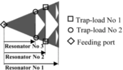
Fig. 1. Trap-loads locations in the Sierpinski radiating elements for a triband application.
between its multiple resonators. Previously, lumped trap-loads have been already used to design multiband antennas [2], [5]. Moreover the proposed antenna is back-loaded with a cutoff and open-ended metallic waveguide. This original configura-tion allows a good tradeoff between the rear radiaconfigura-tion and the impedance matching of the antenna. Measurements presented in this Letter confirm the expected multiband behavior and the circular polarization of the proposed antenna.
II. ANTENNADESCRIPTION
The multiband behavior of the antenna is achieved by using Sierpinski radiating elements with appropriate integrated trap-loads or lumped band-stop filters. An elementary lossless lumped-element trap-load consists of a shunted capacitive element C with an inductive element L. This circuit is char-acterized by a rejected frequency band defined at the center frequency . Conditions for impedance matching and finite available components values enable us to limit the choice to a few numbers of couple (L, C). A triband (at operating frequencies and , with ) Sierpinski triangle antenna with trap-loads is shown in Fig. 1. Two different types of trap-loads are used in this Sierpinski ra-diating element: trap-load No. 1 with resonant frequency sets at and trap-load No. 2 with resonant frequency sets at . These trap-loads do not reject the lowest frequency and therefore allow the resonator No1 to operate at its resonant frequency . Since the trap-load No. 1 is equivalent to an open-circuit at the intermediate frequency , the monopole is equivalent to the resonator No. 2 and then, it operates at frequency . Finally, at the trap-load No. 2 is in the blocked state, and consequently, the monopole is equivalent to the shortest element (resonator No. 3) operating at .
Two configurations can create circularly polarized radiating fields from this linearly polarized antenna element: the first con-figuration uses quadratic phase excitations placed at the center of the structure while for the second configuration, the quadratic
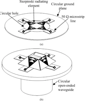
Fig. 2. Sierpinski antenna with border excitation: (a) the planar configuration, (b) the pyramidal configuration ( : Feeding ports).
phase excitations are located at the border of the antenna [see Fig. 2(a)]. According to electromagnetic simulations (not shown here), it can be observed that the latter configuration provides higher directivity with wider bandwidth as compared to the first one. Furthermore, the four feeding ports in this second con-figuration are all disjointed, making it easier to feed in prac-tice. However, this configuration suffers from undesirable inter-ferences due to the array effect induced by the nonhomothetic shape of the antenna, this effect increasing with the frequency. In addition it may present relatively low radial directivity at high frequencies. The natural solution to overcome these two draw-backs consists of exploiting the axis perpendicular to the an-tenna surface. The resulting pyramidal anan-tenna [see Fig. 2(b)] provides a better radial radiation, hence possible improvement in the radial directivity. Additionally, with this configuration, the feeding ports are brought closer to each other, leading to a reduction or even suppression of the abovementioned undesir-able array effect. In many cases, pyramids with an inclination angle of 45 present a good tradeoff between the expected ra-dial and axial radiation performance. The outer radius of the circular ground plane is chosen in order to reduce the edge ra-diation produced by the surface current on the ground plane.
We have observed, for the first time to our knowledge, that an excellent impedance matching at all operating frequencies is obtained when 1) a hole is made in the metallic ground plane just below the pyramidal antenna and 2) when the four feeding ports are located at the edge of this hole (see Fig. 2, where 50 -microstrip lines have been used to connect the excita-tion ports—e.g., SMA connectors—to the radiating elements). Without such perforation of the ground plane, a poor impedance matching is observed at many (if not all) operating frequen-cies. However the presence of the hole generates a rear elec-tromagnetic radiation. In order to reduce this undesirable radi-ation, the ground plane is loaded with a cutoff and open-ended
Fig. 3. (a) Dimensions of the radiating elements, (b) the ground plane and the waveguide dimensions, and (c) the manufactured antenna.
metallic waveguide. This metallic waveguide may be viewed as the continuation of the finite-thickness ground plane together with the hole. This waveguide is designed such that no modes are propagating inside at all the operating frequencies of the multiband antenna. Since all modes in the waveguide are attenu-ated, the longer the open-ended waveguide the lower the rear ra-diation. The maximum directivity of rear radiation (at elevation angle of 180 ) is expected at the highest operating frequency be-cause the attenuation constant of the first cutoff mode is lower at this frequency than at the other frequencies. Nevertheless, we have observed that longer the waveguide, poorer the impedance matching of the antenna and the poorest impedance matching is found at the lowest operating frequency. Consequently varying the length of the cutoff open-ended waveguide allows achieving
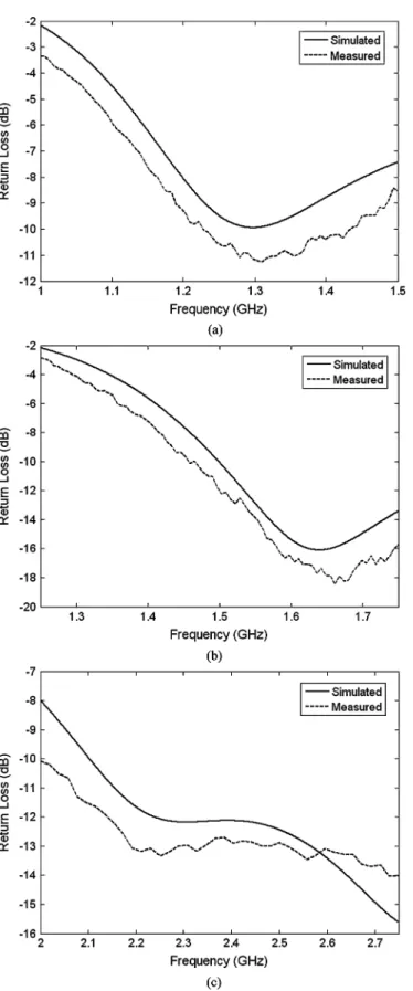
Fig. 4. The simulated and measured return loss for the Sierpinski multiband antenna in (a) the first band, (b) the second band, and (c) the third band.
a good tradeoff between rear radiation and impedance matching at feeding ports.
Fig. 5. Measured and simulated radiation patterns for the multiband antenna at the three operating frequencies: (a) 1.3 GHz, (b) 1.6 GHz, and (c) 2.3 GHz.
III. TRIBANDAPPLICATION
In this section, a triband Sierpinski pyramidal antenna loaded with a cutoff waveguide is designed, simulated and finally mea-sured. The trap-loads in this application are approximated as idealON/OFFswitches both in simulation and measurement. The
desired central frequencies of the three operating bands are GHz, GHz and GHz. The electromagnetic simulations are provided by means of a finite-difference time-domain (FDTD) method using CST Microwave Studio software [6]. The four Sierpinski radiating elements that constitute the antenna are printed with copper on a low-permittivity substrate (relative permittivity and thickness mm) [see Fig. 3(a)]. The same substrate is used for the realization of the 50 -microstrip lines. These microstrip lines have a width of mm and are printed on 30 mm 30 mm boards. The dimensions of the building blocks of the antenna (in par-ticular, the ground plane and the circular waveguide) are given in Fig. 3(b). The outer radius of the ground plane is 97.5 mm. Minor safety margins are added to the radius of the hole that perforates the ground plane in order to avoid any possible man-ufacturing defects. The cutoff open-ended metallic waveguide used for controlling the rear radiation and impedance matching has an inner radius of 38.35 mm and a length of 70 mm. This length is set to reduce the rear electromagnetic radiation. Fi-nally, a pyramidal inclination of 45 degrees is selected as a good tradeoff between the radial and axial radiation performance. The final manufactured antenna is shown in Fig. 3(c).
Measurements of reflection coefficient at the four input ports were performed using the VNA WILTRON 37269A. During measurements, only one port at a time is excited, the other three being matched (50 ). The simulated and measured return loss results are depicted in Fig. 4. As shown in this figure, the impedance matching of the antenna is good (i.e., the measured return loss is lower than 10 dB) at the three operating fre-quencies GHz, GHz, and GHz. Regarding the interelement coupling at the three operating frequencies, the simulated -parameter takes values between 7.8 dB and 9.6 dB while the simulated -parameter varies between 11.3 dB, and 12.6 dB.
The radiation patterns measurements at the three operating frequencies were performed using the Compact Antenna Test Range (CATR) at CNS (The French Space Agency). Fig. 5 dis-plays the measured as well as the simulated Right Handed (RH-) and Left Handed (LH-) Circular Polarization (CP) directivity patterns of the antenna at the three operating frequencies.
As expected the radiation patterns of the antenna are quasi-hemispheric. Such radiation patterns are appropriate for satellite navigation reception antennas, thus allowing a maximum signal reception from the satellites in sight.
By adjusting the inclination of the four radiation elements, different shapes of the radiation patterns can be obtained. The cross-polarization level is lower than dB in the half space of interest, ensuring a good purity of polarization. Thanks to the cutoff circular waveguide, the maximum of rear radiation direc-tivity is lower than 10 dB at the three operating frequencies.
From these results we conclude that the multiband behavior and the circular polarization of the proposed antenna have been validated experimentally.
IV. CONCLUSION
A novel pyramidal antenna based on Sierpinski triangles loaded with a cutoff metallic waveguide was designed and tested experimentally. The measurement results confirm the good performance of the designed antenna. The original solu-tion that consists of loading the ground plane of the pyramidal antenna by a cutoff and open-ended metallic waveguide pro-posed here has been developed for a triband application but, it can also be advantageously applied for applications with more frequency bands. Moreover, the exploitation of available volume offers various degrees of freedom for the pyramidal antenna design such as the angle of inclination of the pyramid and the radius of the circular hole bored in the ground plane as well as the length of the back-loaded cylinder. Due to its multiband property, the proposed pyramidal antenna can be used to replace heavier combinations of two or more single band antennas. For example this antenna can be used for both radio-navigation (GPS, Galileo ) and telemetry applications.
REFERENCES
[1] S. Hebib, H. Aubert, O. Pascal, N. Fonseca, L. Ries, and J. M. Lopez, “Pyramidal multiband antennas for GPS/Galileo/microsat application,” in Proc. IEEE Antennas Propag. Soc. Int. Symp., Jun. 10-15, 2007, pp. 2041–2044.
[2] S. Hebib, H. Aubert, O. Pascal, N. Fonseca, L. Ries, and J. M. Lopez, “Trap-loaded pyramidal triband antenna for satellite applications,” in Proc. IEEE Antennas Propag. Soc. Int. Symp., San Diego, CA, Jul. 7–12, 2008, pp. 1–4.
[3] S. R. Best, “On the radiation pattern characteristics of the sierpinski and modified Parany gasket antennas,” IEEE Antennas Wireless Propag. Lett., vol. 1, no. 1, pp. 39–42, 2002.
[4] J. P. Gianvittorio and Y. Rahmat-Samii, “Fractal Yagi antennas: De-sign, simulation, and fabrication,” Microw. Opt. Technol. Lett., vol. 41, no. 5, pp. 375–380, Jun. 2004.
[5] B. Rama Rao, M. A. Smolinski, C. C. Quach, and E. N. Rosario, “Triple-band GPS trap-loaded inverted l antenna array,” Microw. Opt. Technol. Lett., vol. 38, no. 1, pp. 35–37, Jul. 2003.