Publisher’s version / Version de l'éditeur:
Journal of the Electrochemical Society, 156, 10, 2009
READ THESE TERMS AND CONDITIONS CAREFULLY BEFORE USING THIS WEBSITE. https://nrc-publications.canada.ca/eng/copyright
Vous avez des questions? Nous pouvons vous aider. Pour communiquer directement avec un auteur, consultez la première page de la revue dans laquelle son article a été publié afin de trouver ses coordonnées. Si vous n’arrivez pas à les repérer, communiquez avec nous à [email protected].
Questions? Contact the NRC Publications Archive team at
[email protected]. If you wish to email the authors directly, please see the first page of the publication for their contact information.
NRC Publications Archive
Archives des publications du CNRC
This publication could be one of several versions: author’s original, accepted manuscript or the publisher’s version. / La version de cette publication peut être l’une des suivantes : la version prépublication de l’auteur, la version acceptée du manuscrit ou la version de l’éditeur.
For the publisher’s version, please access the DOI link below./ Pour consulter la version de l’éditeur, utilisez le lien DOI ci-dessous.
https://doi.org/10.1149/1.3194800
Access and use of this website and the material on it are subject to the Terms and Conditions set forth at
Ternary PtRuNi nanocatalysts supported on N-doped carbon
nanotubes: deposition process, materials characterization, and
electrochemistry
Sun, C-L.; Hsu, Y-K.; Lin, Y-G.; Chen, K-H.; Bock, C.; MacDougall, Barry;
Wuy, X.; Chen, L-C.
https://publications-cnrc.canada.ca/fra/droits
L’accès à ce site Web et l’utilisation de son contenu sont assujettis aux conditions présentées dans le site LISEZ CES CONDITIONS ATTENTIVEMENT AVANT D’UTILISER CE SITE WEB.
NRC Publications Record / Notice d'Archives des publications de CNRC:
https://nrc-publications.canada.ca/eng/view/object/?id=5beee240-74c1-4734-b51f-54d9244540f0
https://publications-cnrc.canada.ca/fra/voir/objet/?id=5beee240-74c1-4734-b51f-54d9244540f0
Ternary PtRuNi Nanocatalysts Supported on N-Doped Carbon
Nanotubes: Deposition Process, Material Characterization,
and Electrochemistry
Chia-Liang Sun,a,zYu-Kuei Hsu,bYan-Gu Lin,bKuei-Hsien Chen,b,
*
Christina Bock,c,
*
Barry MacDougall,c,**
Xiaohua Wu,dand Li-Chyong Chene,*
a
Department of Chemical and Materials Engineering, Chang Gung University, Tao-Yuan 333, Taiwan
b
Institute of Atomic and Molecular Sciences, Academia Sinica, Taipei 10617, Taiwan c
Institute of Chemical Process and Environmental Technologies and dInstitute of Microstructural Sciences, National Research Council of Canada, Ontario K1A 0R6, Canada
e
Center for Condensed Matter Sciences, National Taiwan University, Taipei 10617, Taiwan
One-dimensional electrodes consisting of N-doped carbon nanotubes and ternary PtRuNi metal catalysts deposited via a vacuum deposition are made. Material analysis shows that high density nanoparticles that are well dispersed on the nanotube surface are deposited. The average catalyst particle size is between 3 and 4.5 nm depending on the sputtering conditions. The methanol oxidation current of the ternary PtRuNi catalysts increases up to a factor of 2.6 as compared to the binary PtRu catalyst. Our studies shed light on the advanced control of nanotube-supported electrocatalysts under a low loading via the vacuum deposition techniques and can contribute to the controlled synthesis and understanding of fuel-cell catalysts.
© 2009 The Electrochemical Society. 关DOI: 10.1149/1.3194800兴 All rights reserved.
Manuscript submitted October 7, 2008; revised manuscript received July 7, 2009. Published August 13, 2009.
Studies of electrocatalysis for fuel-cell reactions are central to the development of fuel cells 共FCs兲.1More specifically, seeking the best electrode materials consisting of carbon-supported electrocata-lysts plays a key role in the route toward enhanced and optimized FC performance. One-dimensional 共1D兲 carbon nanomaterials, such as carbon nanotubes 共CNTs兲 and nanofibers, have drawn substantial
attention as the support materials for electrocatalytic
nanoparticles.2-9It is further reported that the direct growth of CNTs on the gas diffusion layer 共GDL兲, usually carbon cloth 共CC兲 or car-bon paper inserted between the bipolar plate and catalyst layer, can increase the output power under a low catalyst loading in FC tests.10-12Recently, nitrogen-doped carbon nanotubes 共NCNTs兲 have been used in the electrode layers in FCs and supercapacitors. Re-garding the catalyst support for the FC applications, Lin et al. re-ported that adding appropriate N doping in CNTs can prevent Pt agglomerates on pure, undoped CNTs and results in nearly mono-disperse Pt nanoparticles.13Fang demonstrated that NCNTs can help RuO2and V2O5dispersion and can thus obtain a higher capacitance
than that obtained using undoped CNTs in supercapacitor applications.14-16Therefore, in this paper, we continue to put our efforts toward taking advantage of NCNTs/GDLs as the support materials for catalysts in FCs.
Pt- and PtRu-based nanoparticles with large surface-to-volume ratios have been of major interest for FCs since the 1960s.17-19To date, their controlled synthesis has been widely studied with respect to composition, size, shape, and facet control.20-24However, to the best of our knowledge, there is still limited research on the control-lable synthesis of electrocatalysts on NCNTs/GDLs. Among the re-ported catalyst preparation methods, thin-film deposition has been employed to make a nanostructured catalyst layer.25-29Hence, in this work, a scalable vacuum-sputtering process is investigated to form the nanometer-sized electrocatalysts on NCNTs/GDLs.12,30,31 Sta-menkovic et al. reported that Ni can tailor the electronic structure of Pt in Pt3Ni共111兲 for improved oxygen reduction activity.
32
The ad-dition of Ni to the Pt and PtRu catalysts as a possible enhancing
agent for the methanol electro-oxidation reaction is also
examined.33-35Park et al. claimed that the enhancement in the rates of methanol oxidation in their study was due to the changed elec-tronic structure of the Pt component in PtNi and PtRuNi alloys vs
those in Pt and PtRu.33Therefore, in this study, we use the sputter-ing method to fabricate binary PtRu and ternary PtRuNi nanostruc-tured catalysts on NCNTs/CC and investigate them. The interplays between the structure and electrochemical activities of the formed catalysts on the NCNTs are addressed.
Experimental
Growth of NCNTs.— NCNTs were directly grown on CC
共desig-nation A, E-TEK兲 using a combi共desig-nation of ion beam sputtering depo-sition 共IBSD兲 and microwave-plasma-enhanced chemical vapor deposition 共MPECVD兲 techniques.12They are referred to here as NCNT/CC, and they served as substrates for the electrocatalysts. The iron was sputtered on the CC as a catalyst layer by IBSD to grow NCNTs on the CC. The working pressure was maintained at 5 ⫻ 10−4 Torr in an atmosphere of argon during deposition, and a
Kaufman ion source was operated at a beam voltage of 1250 V and a current of 20 mA. The deposition time of the iron catalyst layer was 10 min. Following deposition, CC coated with an iron catalyst layer was then introduced to MPECVD. The hydrogen plasma treat-ment was operated at 1 kW and a chamber pressure of 28 Torr for 10 min. In this step, the iron catalyst layer was transformed into nano-particles. Hydrogen plasma treatment not only reduced the iron ox-ides on the surface of the iron catalyst layer to the iron metal state but also generated more active catalyst sites. The NCNTs were grown in a gas mixture of H2/CH4/N2 共80:20:80兲 at a microwave
power of 2 kW, a chamber pressure of 45 Torr, and a substrate temperature of 900°C for 10 min.
Electrocatalyst deposition.— The physical vapor deposition
共PVD兲 method was used to deposit platinum 共Pt兲, ruthenium 共Ru兲, and nickel 共Ni兲 on the NCNT/CC substrates. Three sputtering guns 共AJA International, Inc.兲 equipped with shutters were adopted in our multiple-gun sputtering system. When performing the sputtering process, we used a dc-reactive power generator 共ENI RPG 50, MKS Instrument, Inc.兲 for Pt and radio-frequency 共rf兲 power supplies and match networks 共ATX-600 and RFX-600, Advanced Energy兲 for Ru and Ni. The sputter power for Pt and Ru was maintained at 60 and 40 W, respectively, while those for Ni were varied from 0 to 20 W. The Pt, Ru, and Ni targets were placed inside the rf planar magne-tron sputtering guns in a multiple-gun PVD system. The deposition procedure was conducted for 60 min in an argon atmosphere at a working pressure of 5 ⫻ 10−2 Torr and at room temperature. The
holder rotated at a constant speed 共20 rpm兲 during deposition to yield a highly uniform coating of nanoclusters on NCNTs. There are some limitations for preparing electrocatalysts via vacuum
deposi-*Electrochemical Society Active Member.
**Electrochemical Society Fellow.
z
tion. For example, the carbon support should be kept dry due to the requirement of vacuum in the processing. Through vacuum deposi-tion, the catalyst layer with uniform distribution is relatively thin because of the shadow effect compared with the conventional method.
Electrochemical testing of the NCNT/CC-supported catalysts.—
Electrocatalyst-coated NCNT/CC substrates were formed into work-ing electrodes by attachwork-ing a Au wire. Both sides of the workwork-ing electrodes were exposed to the electrolyte solution. Three compart-ment cells, in which the reference electrode was separated from the working and counter electrode compartments by a Luggin capillary, were employed for the electrochemical studies. A saturated calomel electrode 共SCE兲 was used as the reference electrode. However, all potentials in this work are reported vs the reversible hydrogen
elec-trode 共RHE兲 using a potential difference for SCE vs RHE. A large surface area Pt gauze served as the counter electrode. American Chemical Society grade chemicals and high resistivity 18 M⍀ wa-ter were used. CO was adsorbed onto the electrodes at 0.15 V by bubbling CO gas through the 0.5 M H2SO4solution for 20 min. CO
solution was subsequently removed by bubbling high purity argon gas for 40 min, maintaining the potential at 0.15 V. The potential was then cycled for two cycles at a rate of 10 mV s−1. The inter-section between the COadsoxidation peak and its background in the
first two cycles was picked up as onset potential 共Eon兲.
Instrumentations and techniques.— Electrochemical experiments
were performed using a Solartron SI 1287 potentiostat/galvanostat 共Solartron Group Ltd.兲 computer controlled by Corrware software 共Scribner Assoc.兲. A Bruker D8 advance X-ray diffraction 共XRD兲 system was employed to obtain XRD patterns. The scanning angle 2 extended from 30 to 90°. X-ray photoelectron spectroscopy 共XPS兲 spectra were obtained using a Kratos Axis Ultra spectrometer. A Hitachi S-4800 scanning electron microscope 共SEM兲 and a trans-mission electron microscope 共TEM, JEOL JEM-2100F兲 were em-ployed to obtain morphological information on the catalyst samples
Table I. Characteristics of 1D composite nanoelectrodes.
Catalysta 共W兲 Ptb 共atom %兲 Rub 共atom %兲 Nib 共atom %兲 d220c 共nm兲 Ipeakd 共mA/cm2兲 Eon e 共V兲 Efwhme 共mV兲 PtRu 49.1 50.9 0 4.5 5.6 0.44 147 ⫾ 18 PtRuNi 共5 W兲 44.8 53.3 1.9 3.8 9.2 0.45 165 ⫾ 18 PtRuNi 共10 W兲 43.5 53.0 3.5 3.0 14.5 0.46 159 ⫾ 13 PtRuNi 共20 W兲 49.6 45.8 4.6 3.5 11.6 0.40 85 ⫾ 9
aThe numbers in brackets denote the Ni gun powers in multiple-gun magnetron sputtering process. bPt:Ru:Ni surface ratios were derived from the XPS spectra.
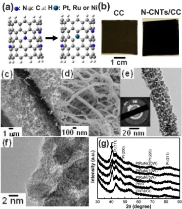
cThe average particle sizes were determined by resolving the Scherrer equation using Pt-based 共220兲 peaks in Fig.1g. dMethanol oxidation currents were recorded in forward scans in Fig.3a.
eE
onand Efwhm共COads→ CO2兲 were estimated using COadsoxidation peaks in Fig.3b. These potentials are referred to the RHE.
(b)
(a)
N-CNTs/CC CC 1 cm : N : C : H : Pt, Ru or Ni(b)
(a)
N-CNTs/CC CC 1 cm 1 cm : N : C : H : Pt, Ru or Ni 30 40 50 60 70 80 90(g)
CNTs/CC PtRu PtRuNi(5W) PtRuNi(10W) Pt (2 2 0 ) Pt (2 0 0 ) P t (3 1 1 ) Pt (1 1 1 ) In te n s ity (a .u .) 2θθ(degree) PtRuNi(20W) 30 40 50 60 70 80 90(g)
CNTs/CC PtRu PtRuNi(5W) PtRuNi(10W) Pt (2 2 0 ) Pt (2 0 0 ) P t (3 1 1 ) Pt (1 1 1 ) In te n s ity (a .u .) 2θθ(degree) PtRuNi(20W)Figure 1. 共Color online兲 共a兲 Atomistic models of the NCNT and metal-attached NCNT clusters. 共b兲 E-TEK CC before and after growing NCNTs. 共c兲 SEM images of NCNTs on CC. 共d兲 High magnification SEM images of electrocatalyst-coated NCNTs. 共e兲 TEM image of a single nanocable. Inset is the corresponding selected area electron diffraction pattern of Pt-based alloy. 共f兲 High resolution TEM image of nanosized catalysts on nanocable surface. 共g兲 XRD patterns of nanocable electrodes fabricated under a variety of sput-tering conditions. 80 76 72 68 PtRuNi(20W) PtRuNi(10W) PtRuNi(5W) 4f7/2 4f5/2 PtRu (a) Pt 4f
Binding Energy (eV)
In te n s it y (a .u .) 292 288 284 280 276 3d5/2 3d3/2 PtRuNi(20W) PtRuNi(10W) PtRuNi(5W) PtRu (b) Ru 3d
Binding Energy (eV)
In te n s ity (a .u .) 890 880 870 860 850 (c) Ni 2p 2p 3/2 2p1/2 PtRuNi(20W) PtRuNi(10W) PtRuNi(5W) PtRu
Binding Energy (eV)
In te n s ity (a .u .) 500 490 480 470 460 450 3p3/2 3p1/2 PtRuNi(20W) PtRuNi(10W) PtRuNi(5W) PtRu (d) Ru 3p
Binding Energy (eV)
In te n s it y (a .u .)
Figure 2.XPS 共a兲 Pt 4f, 共b兲 Ru 3d, 共c兲 Ni 2p, and 共d兲 Ru 3p spectra of 1D composite nanoelectrodes synthesized at different Ni sputtering powers.
B1250 Journal of The Electrochemical Society, 156 共10兲 B1249-B1252 共2009兲
and substrates. The mass per unit area of the metals was determined by inductively coupled plasma–optical emission spectroscopy 共ICP-OES, PerkinElmer ICP-OES Optima 125 3000兲. In this paper, all samples were loaded with approximately 0.2 mg Pt per geometry area of each square centimeter.
Results and Discussion
Figure 1ashows the atomistic models of N dopants in zigzag 共10,0兲 nanotube clusters with and without metal attachment.31,32It is reported that the extrinsic N dopants can help metal catalyst disper-sion on NCNTs.12-16,30,31Therefore, we suggest that the metal atom stays around the N dopant sites in our models. Figure1b-dillustrates the morphology of NCNTs directly grown on the E-TEK CC. In Fig.
1b, the E-TEK CC with the NCNTs on top turns black compared with the “as-received” gray CC sample on the left side. Figure1c
shows that the porous CC is the ensemble of carbon fibers with diameters of several tens of micrometers as a GDL. Figure 1c, shows that a thin NCNT layer can be directly grown on the surface of carbon fibers. Subsequently, the magnetron sputtering is per-formed to deposit Pt, Ru, and Ni on NCNTs/CC. After sputtering, the high magnification SEM image in Fig.1dshows the high surface area, catalyst-coated NCNT. Figure1eis the TEM micrograph of a single catalyst-coated NCNT with a darker contrast than the un-coated CNT. It is quite clear that PVD can generate high density nanocatalysts on the sidewall to form the shell of a nanocable. In Fig.1f, the clear lattice fringe of the nanocrystals, with the particle size as small as several nanometers, is observed. Figure1gshows the XRD patterns of multicomponent catalysts deposited on NCNT/ CC. Notice that the full width at half-maximum 共fwhm兲 of the Pt peak changes along with the adjustment of the Ni sputtering power when the power for Pt and Ru is kept constant. Comparing all the 共220兲 peaks, the minimal particle size of 3.0 nm is derived for PtRuNi 共10 W兲. This size change is attributed to the modified nucle-ation and growth of nanocatalysts on NCNTs, resulting in different particle sizes and densities after adding Ni to the sputtering process. The shift of XRD peaks of PtRuNi, relative to those in PtRu, is ascribed to the change in their lattice spacing with Ni.
Figure2displays XPS Pt 4f, Ru 3d, Ni 2p, and Ru 3p spectra of 1D composite nanoelectrodes synthesized at different Ni sputtering powers. The dashed lines indicate the peak position for each zero-valence transition metal. Positive shifts of Pt 4f5/2and Pt 4f7/2from
those of pure Pt were observed on all alloy samples, suggesting the lowering of the Fermi level or the increase in the valence electron vacancy.36,37These shifts suggest that Ru and Ni alter the electronic structure of Pt and could enhance the catalytic activity of Pt for methanol oxidation. In all alloys, the shoulder of Ru 3d3/2 and
Ru 3d5/3 in high binding energy corresponds to the existence of
RuO2and RuO3; these oxidation states aid in improving methanol
oxidation by providing Pt-bonded CO with oxygen species.33,34The profound Ru 3d3/2 peak in PtRuNi 共20 W兲 catalyst reveals the
changed electronic structure of Ru with a sufficient amount of Ni and could improve its ability to remove CO on Pt. The less intense Ru 3p region was also analyzed in addition to the main Ru 3d spectra, as the latter overlays the C 1s region. At Ni-containing catalysts, the Ni additive comprises metallic Ni, NiO, Ni共OH兲2, and
NiOOH.33The Ni contents in composite electrodes increase from 0 to 4.6 atom % along with the increasing Ni sputtering power, as indicated in TableI.
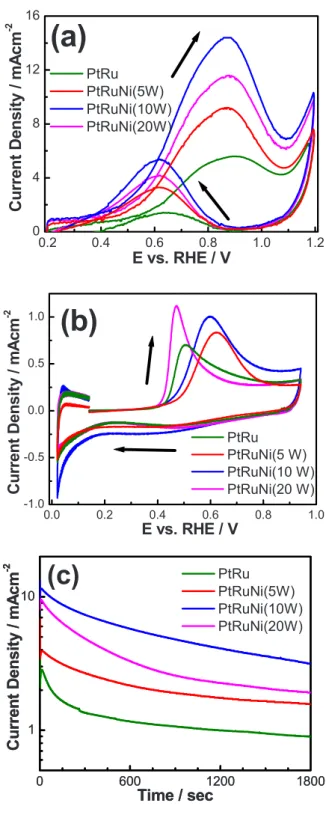
Besides the above-mentioned material analysis results, we fur-ther carried out electrochemical measurements relevant to methanol oxidation. Figure3aillustrates cyclic voltammograms 共CVs兲 of the composite electrodes in 1 M CH3OH + 1 M H2SO4solutions at a
scan rate of 50 mV s−1. The current scale is normalized using the geometrical electrode area. Clearly, the PtRuNi catalysts always have considerably higher peak currents than the binary PtRu. The high Ipeak of the PtRuNi 共10 W兲 catalyst is attributed to the large
reaction surface area associated with the small particle size, as re-vealed by XRD. When the power of the sputtering gun changes, the electrochemical surface areas of the catalysts also change.
Accord-ing to the calculations in the hydrogen adsorption region, the PtRuNi 共10 W兲 catalyst has the highest electrochemical surface area, which is consistent with the XRD result. When the particle size of the catalysts becomes smaller, their electrochemical surface area gets higher. CO-adsorbed 共COads兲 stripping voltammograms were
further employed to investigate nanoparticle surfaces in solution
en-0.2 0.4 0.6 0.8 1.0 1.2 0 4 8 12 16
(a)
PtRu PtRuNi(5W) PtRuNi(10W) PtRuNi(20W)C
u
rr
e
n
t
D
e
n
s
it
y
/
m
A
c
m
-2E vs. RHE / V
0.0 0.2 0.4 0.6 0.8 1.0 -1.0 -0.5 0.0 0.5 1.0(b)
PtRu PtRuNi(5 W) PtRuNi(10 W) PtRuNi(20 W)E vs. RHE / V
C
u
rr
e
n
t
D
e
n
s
it
y
/
m
A
c
m
-2 0 600 1200 1800 1 10C
u
rr
e
n
t
D
e
n
s
it
y
/
m
A
c
m
-2Time / sec
PtRu PtRuNi(5W) PtRuNi(10W) PtRuNi(20W)(c)
0 600 1200 1800 1 10C
u
rr
e
n
t
D
e
n
s
it
y
/
m
A
c
m
-2Time / sec
PtRu PtRuNi(5W) PtRuNi(10W) PtRuNi(20W)(c)
Figure 3. 共Color online兲 共a兲 CVs recorded at 50 mV s−1 in
1 M CH3OH + 1 M H2SO4 solutions for composite nanoelectrodes with
different Ni contents. 共b兲 COadsstripping voltammograms 共the first cycle兲
recorded at 10 mV s−1in 0.5 M H
2SO4solution. 共c兲 Chronoamperometric
measurements of nanocable electrodes fabricated under a variety of sputter-ing conditions recorded at the potential of 0.65 V in 1 M CH3OH
vironments. In Fig.3b, the increase in the COadsstripping peak area
of PtRuNi catalysts has a trend similar to that shown in Ipeak, as a
consequence of an altered particle size. More importantly, the onset potentials 共Eon兲 for the COads oxidation reactions for all catalysts
occur between 0.40 and 0.46 V vs RHE and are comparable to those of PtRu.38,39This benefit is assigned to the bifunctional mechanism, i.e., the formation of “Ru–OH” species to release CO-poisoned Pt sites on particle surfaces starting at low potentials.18The COads
oxi-dation reaction is thought to take place according to the bifunctional mechanism as follows
Ru + H2O → Ru–OH + H++ e− 关1兴
M–CO + Ru–OH → M + Ru + CO2+ H++ e− 关2兴
In Eq.2, M can be a single Pt, Ru, or Ni monoatomic site on the catalyst surface onto which CO can absorb. As indicated in Fig.3b, the lowest Eon and the narrowest potential fwhm 共Efwhm兲 are
ob-served for the PtRuNi 共20 W兲 catalyst, suggesting a better oxidation kinetics for the complete COads to CO2 oxidation than other
cata-lysts. This advantage in COadsoxidation kinetics is likely due to the
modified atomistic distribution, electronic structure, and particle size of the catalyst particles and their individual components.40,41In Fig.
3c, the chronoamperometric measurements show that the PtRuNi 共10 W兲 catalyst has the highest performance for methanol oxidation.
Conclusion
The preparation and performance of NCNT-supported PtRuNi electrocatalysts are reported. Compared to the PtRu catalyst, the PtRuNi catalyst exhibits a higher methanol oxidation current and a lower COadsstripping potential. Our studies shed light on the
ad-vanced control of nanometer-sized catalysts on 1D NCNTs for FC technologies.
Acknowledgments
The authors gratefully acknowledge the financial support from the National Science Council of Taiwan, the National Research Council of Canada, and AFOSR/AOARD. We thank D. Kingston 共NRC, Ottawa兲 for his assistance with SEM and XPS.
Chang Gung University assisted in meeting the publication costs of this article.
References
1. S. Srinivasan, Fuel Cells: From Fundamentals to Applications, Springer, New York 共2006兲.
2. G. Che, B. B. Lakshmi, E. R. Fisher, and C. R. Martin, Nature (London), 393, 346 共1998兲.
3. C. A. Bessel, K. Laubernds, N. M. Rodriguez, and R. T. K. Baker, J. Phys. Chem. B, 105, 1115 共2001兲.
4. Z. L. Liu, X. H. Lin, J. Y. Lee, W. Zhang, M. Han, and L. M. Gan, Langmuir, 18, 4054 共2002兲.
5. E. S. Steigerwalt, G. A. Deluga, and C. M. Lukehart, J. Phys. Chem. B, 106, 760 共2002兲.
6. W. Z. Li, C. H. Liang, W. J. Zhou, J. S. Qiu, Z. H. Zhou, G. Q. Sun, and Q. Xin, J. Phys. Chem. B, 107, 6292 共2003兲.
7. G. Girishkumar, K. Vinodgopal, and P. V. Kamat, J. Phys. Chem. B, 108, 19960 共2004兲.
8. C. Kim, Y. J. Kim, T. Yanagisawa, K. C. Park, M. Endo, and M. S. Dresselhaus, J. Appl. Phys., 96, 5903 共2004兲.
9. S. Liao, K. A. Holmes, H. Tsaprailis, and V. I. Briss, J. Am. Chem. Soc., 128, 3504 共2006兲.
10. X. Sun, R. Li, D. Viller, J. P. Dodelet, and S. Desilets, Chem. Phys. Lett., 379, 99 共2003兲.
11. C. Wang, M. Waje, X. Wang, J. M. Tang, R. C. Haddon, and Y. Yan, Nano Lett., 4, 345 共2004兲.
12. C. H. Wang, H. Y. Du, Y. T. Tsai, C. P. Chen, C. J. Huang, L. C. Chen, K. H. Chen, and H. C. Shih, J. Power Sources, 171, 55 共2007兲.
13. Y. G. Lin, Y. K. Hsu, C. T. Wu, S. Y. Chen, K. H. Chen, and L. C. Chen, Diamond Relat. Mater., 18, 433 共2009兲.
14. W. C. Fang, Nanotechnology, 19, 165705 共2008兲.
15. W. C. Fang and W. L. Fang, Chem. Commun. (Cambridge), 2008, 5236. 16. W. C. Fang, K. H. Chen, and L. C. Chen, Nanotechnology, 18, 485716 共2007兲. 17. J. O’M. Bockris and H. Wroblowa, J. Electroanal. Chem., 7, 428 共1964兲. 18. M. Watanabe and S. Motoo, J. Electroanal. Chem. Interfacial Electrochem., 60,
267 共1975兲.
19. M. Watanabe, in Catalysis and Electrocatalysis at Nanoparticle Surfaces, A. Wieckowski, E. R. Savinova, and C. G. Vayenas, Editors, pp. 827–845, Marcel Dekker, New York 共2003兲.
20. E. Reddington, A. Sapienza, B. Gurau, R. Viswanathan, S. Sarangapani, E. S. Smotkin, and T. E. Mallouk, Science, 280, 1735 共1998兲.
21. C. Bock, C. Paquet, M. Couillard, E. A. Botton, and B. R. MacDougall, J. Am. Chem. Soc., 126, 8028 共2004兲.
22. C. Burda, X. Chen, R. Narayanan, and M. A. El-Sayed, Chem. Rev. (Washington, D.C.), 105, 1025 共2005兲.
23. T. He, E. Kreidler, L. Xiong, J. Luo, and C. J. Zhong, J. Electrochem. Soc., 153, A1637 共2006兲.
24. N. Tian, Z.-Y. Zhou, S.-G. Sun, Y. Ding, and Z. L. Wang, Science, 316, 732 共2007兲.
25. M. K. Debe, in Handbook of Fuel Cells, Fundamentals, Technology and Applica-tions, Vol. 3, W. Vielstich, A. Lamm, and H. A. Gasteiger, Editors, pp. 576–589, John Wiley & Sons, Chichester, U.K. 共2003兲.
26. C. K. Witham, W. Chun, T. I. Valdez, and S. R. Narayanan, Electrochem. Solid-State Lett., 3, 497 共2000兲.
27. A. T. Haug, R. E. White, J. W. Weidner, W. Huang, S. Shi, N. Rana, S. Grunow, T. C. Stoner, and A. E. Kaloyeros, J. Electrochem. Soc., 149, A868 共2002兲. 28. T. Nakakubo, M. Shibata, and K. Yasuda, J. Electrochem. Soc., 152, A2316
共2005兲.
29. P. Bommersbach, M. Mohamedi, and D. Guay, J. Electrochem. Soc., 154, B876 共2007兲.
30. C. L. Sun, L. C. Chen, M. C. Su, L. S. Hong, O. Chyan, C. Y. Hsu, K. H. Chen, T. F. Chang, and L. Chang, Chem. Mater., 17, 3749 共2005兲.
31. C. L. Sun, H. W. Wang, M. Hayashi, L. C. Chen, and K. H. Chen, J. Am. Chem. Soc., 128, 8368 共2006兲.
32. V. R. Stamenkovic, B. Fowler, B. S. Mun, G. Wang, P. N. Ross, C. A. Lucas, and N. M. Marković, Science, 315, 493 共2007兲.
33. K. W. Park, J. H. Choi, B. K. Kwon, S. A. Lee, Y. E. Sung, H. Y. Ha, S. A. Hong, H. Kim, and A. Wieckowski, J. Phys. Chem. B, 106, 1869 共2002兲.
34. J. H. Choi, K. W. Park, B. K. Kwon, and Y. E. Sung, J. Electrochem. Soc., 150, A973 共2003兲.
35. A. Gore, U.S. Pat. 6,921,605 共2005兲.
36. T. Toda, H. Igarashi, and M. Watanabe, J. Electrochem. Soc., 145, 4185 共1998兲. 37. T. Toda, H. Igarashi, H. Uchida, and M. Watanabe, J. Electrochem. Soc., 146, 3750
共1999兲.
38. C. Bock, B. MacDougall, and Y. LePage, J. Electrochem. Soc., 151, A1269 共2004兲. 39. C. Bock, M.-A. Blakely, and B. MacDougall, Electrochim. Acta, 50, 2401 共2005兲. 40. B.-J. Hwang, L. S. Sarma, J.-M. Chen, C.-H. Chen, S.-C. Shih, G.-R. Wang, D.-G.
Liu, J.-F. Lee, and M.-T. Tang, J. Am. Chem. Soc., 127, 11140 共2005兲. 41. D.-Y. Wang, C.-H. Chen, H.-J. Yan, Y.-L. Lin, P.-Y. Huang, B.-J. Hwang, and C.-C.
Chen, J. Am. Chem. Soc., 129, 1538 共2007兲.
B1252 Journal of The Electrochemical Society, 156 共10兲 B1249-B1252 共2009兲