HAL Id: hal-01032155
https://hal.archives-ouvertes.fr/hal-01032155
Submitted on 12 Dec 2017
HAL is a multi-disciplinary open access
archive for the deposit and dissemination of
sci-entific research documents, whether they are
pub-lished or not. The documents may come from
teaching and research institutions in France or
abroad, or from public or private research centers.
L’archive ouverte pluridisciplinaire HAL, est
destinée au dépôt et à la diffusion de documents
scientifiques de niveau recherche, publiés ou non,
émanant des établissements d’enseignement et de
recherche français ou étrangers, des laboratoires
publics ou privés.
Biomechanics of buttressed trees: bending strains and
stresses
Bruno Clair, Meriem Fournier, Marie-Françoise Prevost, Jacques Beauchêne,
Sandrine Bardet
To cite this version:
Bruno Clair, Meriem Fournier, Marie-Françoise Prevost, Jacques Beauchêne, Sandrine Bardet.
Biome-chanics of buttressed trees: bending strains and stresses. American Journal of Botany, Botanical
Society of America, 2003, 90 (9), pp.1349-1356. �10.3732/ajb.90.9.1349�. �hal-01032155�
B
IOMECHANICS OF BUTTRESSED TREES
:
BENDING STRAINS AND STRESSES
1B
RUNOC
LAIR,
2M
ERIEMF
OURNIER,
2,5M
ARIEF
RANC¸ OISEP
REVOST,
3J
ACQUESB
EAUCHENE,
2 ANDS
ANDRINEB
ARDET42UMR, Ecologie des Foreˆts de Guyane, CIRAD ENGREF INRA, Campus Agronomique, BP 709, 97310 Kourou, Guyane Franc¸aise,
France;3UMR, Botanique et Bioinformatique de l’architecture des plantes AMAP, IRD Centre de Cayenne, BP 165, 97323
Cayenne, Guyane Franc¸aise, France; and4Laboratoire de Me´canique et de Ge´nie Civil, UMR 5508 CNRS Universite´ de Montpellier
II, cc 081, Bat 13, Place Eugene Bataillon, 34095 Montpellier Cedex 5, France
The different hypotheses about buttress function and formation mainly involve mechanical theory. Forces were applied to two trees of Sloanea spp., a tropical genus that develops typical thin buttresses, and the three-dimensional strains were measured at different parts of the trunk base. Risks of failure were greater on the buttress sides, where shear and tangential stresses are greater, not on the ridges, in spite of high longitudinal (parallel to the grain) stresses. A simple beam model, computed from the second moment of area of digitized cross sections, is consistent with longitudinal strain variations but cannot predict accurately variations with height. Patterns of longitudinal strain variation along ridges are very different in the two individuals, owing to a pronounced lateral curvature in one specimen. The constant stress hypothesis is discussed based on these results. Without chronological data during the development of the tree, it cannot be proved that buttress formation is activated by stress or strain.
Key words: biomechanics; buttress; Eleaocarpaceae; French Guiana; Sloanea spp.; tropical trees; wood.
Buttresses, lateral flanges joining the roots and the trunk,
have intrigued generations of biologists. Large buttresses are
quite rare in temperate areas, but very characteristic among a
remarkable variety of tropical stem forms. Buttress occurrence
and form within one species are quite fixed traits, although
some species are relatively variable in this respect. Buttress
characterization is also of significant practical interest in
iden-tifying tropical trees (Gentry, 1993). A number of different
biological theories have tried to explain the function and the
formation of buttresses (Kaufman, 1988; Richards, 1995).
Some authors assumed that physiological stresses force aerial
development of shallow root systems (Halle et al., 1978).
Oth-ers assumed that buttresses prevent climbing by woody vines
or reduce competition with other trees by occupying available
space (Black and Harper, 1979). Lastly, as the term ‘‘buttress’’
suggests, there is a general consensus that these structures are
of mechanical importance (Kaufman, 1988; Mattheck, 1991;
Ennos, 1993, 1995; Young and Perkocha, 1994; Chapman et
al., 1998). However the actual function has not been
empiri-cally demonstrated, and such theories assume that buttresses
are of adaptive value in resisting wind or gravity forces or are
formed via mechanistic constraints based on hypotheses of
stimulated growth in mechanically stressed zones of the trunk
base.
There is only limited experimental and theoretical work on
how buttresses act mechanically. Mattheck’s group (Mattheck,
1990, 1991; Mattheck and Prinz, 1991) assumed that cambial
growth is activated by stress and simulated stresses induced
1Manuscript received 12 November 2002; accepted 4 April 2003.
This work was supported by the general program of the GIS Silvolab Guy-ane, during the ENGREF training courses ‘‘FTH.’’ We thank all the students who participated, especially Bruno and Ce´cile, who made drawings. We wish to acknowledge Guillaume Pasco (field tests), Gae¨lle Jaouen (wood density), Freddi Gallenmu¨ller (literature), and the wood science program of CIRAD Foreˆt in Kourou for valuable help during laboratory experiments. We are very grateful to Nick Rowe who improved the English and critically read the man-uscript.
by a bending moment at the stem base via a finite element
model. By an incremental process that was supposed to
sim-ulate peripheral secondary growth in the tree (Mattheck,
1990), material was added step by step at the wood surface,
where mechanical stresses are greater. Mechanical stresses
were analyzed at each step, until they became constant all
around the trunk and buttress surfaces, under different testing
boundary conditions that simulated anchorage between
but-tresses and underground soil or roots. The forms predicted by
Mattheck’s model were finally compared to existing ones in
nature. Mattheck’s model can explain many patterns of
but-tress form and development observed by ecologists (Ennos,
1993). Although some of the assumptions from such
approach-es are quapproach-estionable, such typapproach-es of mechanical hypothapproach-esapproach-es need
to be validated by experimental measurements of geometries,
material properties, and strains.
Ennos (1995) and Crook et al. (1997) discussed Mattheck’s
theory with simulated windthrow tests and morphological
ob-servations of roots after working on Malaysian trees with and
without buttresses. They observed root movements and trunk
displacement, strains along buttresses, trunk and anchorage
strength, and crack modes on both the leeward and windward
sides.
In this paper, we present experimental results based on a
typical buttressed genus in the lowland tropical rainforest of
French Guiana. The aim was to localize the risks of failure by
directly measuring strains and to discuss Mattheck’s constant
stress hypothesis in the light of these results. We also tested
the ability of a simple beam model to describe strain patterns
under external bending forces.
MATERIALS AND METHODS
Materials—After looking at typical buttresses on small diameter trees, we
selected the genus Sloanea (Eleaocarpaceae), because ‘‘. . . a good habit char-acter is the usual development of unusually thin, frequently large buttresses . . . ’’ (Gentry, 1993, p. 395). This genus is represented by 17 species in French Guiana (Hollowel et al., 2001), 60–70 species in tropical America, and 120 species in the world, all of which are tropical in distribution (Gentry,
1993; Mabberley, 1997). The two trees used in the this experiment were of the same size (20 cm DBH) and located in rainforest in the ‘‘Piste St. Elie’’ field station (53809 W–58209 N). Both trees had three well-developed and thin buttresses. However, in the first tree, buttresses are straight, approximately triangular ‘‘plates.’’ In the second one, the buttress flanges have lateral cur-vatures. Specimens have been donated to the international herbarium of Cay-enne. The first tree has been identified as Sloanea cf. tuerckheimii J. D. Smith; the second one is a different species that has not yet been identified.
Field experiments—Local strains were measured at the periphery of
stand-ing trees. The strain sensors were attached on peripheral wood, after removstand-ing the thin bark, in order to measure wood behavior because wood is the main support tissue. In buttresses, strains were measured with strain gauge sensors (DD1 type; Hottinger Baldwin Messtechnik, Darmstadt, Germany) connected in full bridge mode to a battery-powered strain bridge (Alco system, Captels, S. Matthieu de Treviers, France). The sensors were fitted with steel pins, spaced 13 mm apart. The accuracy of this system of measurement is estimated at 30 microstrains (i.e., 30mm/m).
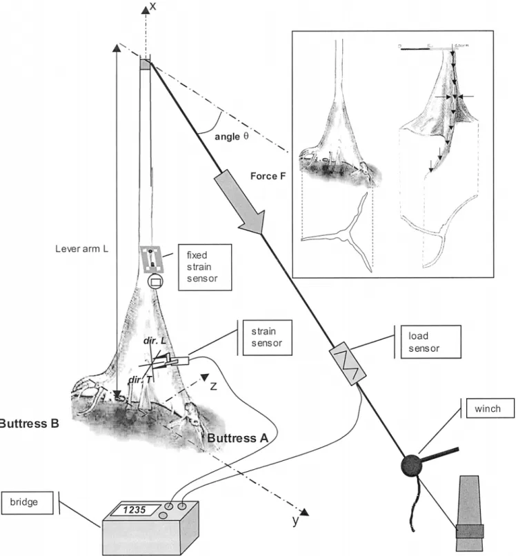
The bending experiment is illustrated in Fig. 1. The trunk was pulled with a manual winch, using a steel cable anchored to the base of another tree nearby. The applied force was measured with a field load cell (Captels). Forc-es were applied at a height of 5 m in five stagForc-es. The main aim during tForc-esting was to remain within the intact structural and linearly elastic material prop-erties; strains were measured at different locations along the ridges and on the sides of the three buttresses by moving the sensors between successive experiments. This approach assumed and checked that the behavior was linear and elastic, so that experiments were repeatable. A mechanical extensometer (Fournier et al., 1994) was fixed on the trunk just above the buttresses and was not moved between successive tests. This ensured repeatability while defining the maximal applied loads. A strain control was chosen with a max-imum of21000 microstrains in the compressed wood of the trunk above the buttresses. After checking the linearity of each test, the slopes«L/F,«T/F,«45/F
(«Lrepresents strain along the grain or longitudinal [L] strain,«Trepresents
strain perpendicular to the grain or tangential [T] strain,«45represents strain
parallel to the diagonal between L and T direction, and F represents applied force) were computed from all five levels of applied force and analyzed for each measurement. According to the definition of the strain tensor and math-ematical formulas for axes changes (Berthelot, 1999), the shear strain«LT/F
was calculated as
« /F 5 « /F 2 (« /F 1 « /F)/2.LT 45 L T
Two sets of bending tests were performed by reversing the direction of force: in both sets, buttress A was lined up with the direction of force. In the first set, this buttress was put into tension; in the second set, the buttress was put into compression.
On the second tree, the force direction was also parallel to one buttress, put in compression. We measured longitudinal strains along the ridge of this buttress and shear strains at two opposite points of the lateral sides. In a final test, we increased the load until the buttress broke and observed how and where the break was initiated.
Model of bending strains—A simple model for longitudinal bending strains
has been designed at the cross section level based on beam theory (strength of materials) that is often used to compute stresses and strains in slender plant axes (Niklas, 1992). The model (see Appendix) uses the following data: the two components (vertical parallel to the trunk and horizontal) of the applied force, the lever arm (vertical distance from the cross section to the applied force), the geometrical characteristics of the cross section (the cross sectional area and the second moments of area that are the relevant geometrical vari-ables to predict flexural stiffness at the cross section level [Niklas, 1992]), and wood stiffness (i.e., Young’s modulus of elasticity of green wood as measured parallel to the grain).
As the model predicts that the longitudinal strain«Lis proportional to the
applied force F and to the modulus of elasticity EL, we will compare
theo-retical and experimental results by analyzing linear regressions between ex-perimental slopes«L/F and theoretical values of«L/ELF. The slopes of these
regressions are estimations of the modulus of elasticity EL.
Additional data—At the end of the field experiment, the tree was felled
above the buttresses. To characterize cross section geometries, slices 10 cm thick with parallel and horizontal surfaces were carefully sawn from the but-tresses. In the laboratory, each surface was photographed and analyzed with the software Optimas 6.5 (Media Cybernetics, Silver Spring, Maryland, USA) to define the outlines and compute (standard functions) for each height x, the center of mass position, the area S(x), and the second moments of area Iy,
Iz(x) and Iyz(x).
Wood basic density (ratio of oven-dried mass to saturated volume) was measured within buttress A (seven heights, three radial positions for each height, two samples for each position), as dried wood density is a good pre-dictor of elastic properties (Kollman and Cote, 1968; Guitard, 1987; Niklas, 1992). Moreover, we adjusted the measured values of basic density to estimate air-dried (i.e., wood moisture content of 12%) density: drying shrinkage is supposed to account for 0.6% of volume per percentage of moisture content loss (CIRAD Foreˆt database on tropical woods, properties of Sloanea spp., J. Ge´rard, CIRAD Foreˆt, Montpellier, France, personal communication) and therefore air-dried density is 1.25 times basic density. We then calculated the modulus of elasticity ELadof air-dried wood, from Guitard’s regressions
(Gui-tard, 1987). The green wood assessment 0.73 ELad(Kollman and Cote, 1968)
were compared to the mentioned slopes of regression. Lastly, Young’s moduli have been measured by tensile tests on air-dried wood samples by the method still used by Clair et al. (2003) and compared to other estimations.
RESULTS
Linearity, elasticity, and repeatability—As expected, each
strain measurement had a linear response to the applied force:
r
2. 0.9 in 83% of the 355 analyzed force vs. strain curves,
r
2, 0.6 in only 3% of analyzed curves. The strain returned
to zero after unloading. Repeatability was very good and, for
each test, the slope of the force-strain curve could be
calcu-lated. Within each set of tests, the variations of these slopes
was very small (CV
, 6%), with no systematic change with
time.
Strain and force magnitudes—During all the bending
ex-periments, measured strains in the different parts of buttresses
remained between
23000 microstrains and 2000 microstrains
along the grain,
25000 microstrains and 1200 microstrains in
the tangential direction, below green wood elastic limit, but
often much higher than the controlled maximal strain in the
trunk of
21000 microstrains. The maximum bending moments
about the base of the tree were 23 500 Nm in the first set and
20 000 Nm in the second. Maximal forces were about 5000 N.
As expected, longitudinal strains, which are the most
intu-itively predictable, were positive (stretching) on buttresses
un-der tension, compressive (shrinking) in the opposite ones.
When the force direction was reversed (second set of tests),
strains were obviously of opposite sign, but of the same
mag-nitude, along the ridges (Fig. 2) and on the buttress sides.
Mean absolute values of longitudinal and shear strains per
unit of basal bending moment,
«
L/FL cos
u and «
LT/FL cos
u,
had the same scale of magnitude, 0.022 microstrains/Nm and
0.017 microstrains/Nm, respectively. Tangential strains were
slightly lower (mean value 0.013 microstrains/Nm).
Longitu-dinal and tangential strains were opposite and had a significant
negative correlation (r
25 0.30), with a slope of 20.64 (Fig.
3). When the data were split, the correlation was greater (r
25 0.53) when keeping only the points closest to the ridge
(
,10 cm), but it was not significant when these points were
removed. Although an exhaustive study of shear strains was
not performed in every part of the three buttresses, smaller
values for all strain components have been measured in
but-Fig. 1. Design of the bending tests and buttress forms of trees of Sloanea spp. Inset: left, first tree, with flat buttresses; right, second tree, with curved buttresses. On the first tree, measurements were made in every part of the buttressed zone. On the second tree, the locations of the measurements are indicated by arrows.
tresses B and C not parallel to the applied force. Therefore,
the following discussion is mainly focused on observations of
buttress A.
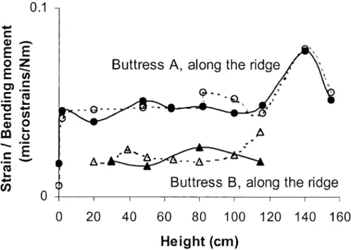
Spatial variations of strains—On the first tree, longitudinal
strains were nearly constant along the ridges, excepted in the
first measured points near the ground at the tip of the root
where they were very small (Fig. 2). They decreased on the
sides, from the buttress ridge to the central trunk (Fig. 4).
On the opposite side, shear strains were minimal near the
ridges and reached maximal values on sides near the trunk
(Fig. 5). In the main buttress studied, buttress A, strain patterns
were similar between the two sides. In the two lateral
buttress-es, some discrepancies were observed from one side to the
Fig. 2 Longitudinal strains measured along the buttress ridges during bending tests performed on one tree of Sloanea cf. tuerckeimii. Solid lines, buttress A is in tension; dotted lines, buttress A is in compression. Circles, results related to buttress A; triangles, results related to buttress B. To allow comparisons, the ratio of strains to the basal bending moment is represented, with absolute values of strains.
Fig. 3. Tangential strains vs. longitudinal strains measured during bending tests performed on one tree of Sloanea cf. tuerckeimii. Open circles represent the zones closest to the ridge (,10 cm). Filled circles represent the sides. The regression is calculated for all the points and is significant (r5 20.55, P , 0.001). The regression line is the principal axis, because both variables play a symmetrical role.
Fig. 4. Measured longitudinal strains per unit of bending moment at the trunk base of Sloanea cf. tuerckeimii, on buttress A side. The buttress and the force are in the same plane, and the buttress is in compression (negative values). Results are given for one side of the buttress as a function of height and distance to the ridge.
other, but no systematic variations were found, and actually,
values of strains were often small.
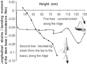
On the second tree, longitudinal strains on the buttress ridge
in parallel to the applied force increased continuously from the
base to the top (Fig. 6). We did only one measurement of the
three-dimensional strain, near the trunk, at 50 cm height, on
both buttress sides (Fig. 1). In fact, shear strain was high (0.05
microstrains/Nm) on the concave side, but almost zero (0.003
microstrains/Nm) on the convex opposite one. The ratio
«
T/
«
Lwas
21.5 on the concave side, 1 on the opposite one.
Observations about breakage—Breakage was initiated by
cracking the wood at the buttress plate (Fig. 7). The
longitu-dinal crack began inside the concave side of the buttress put
in compression. No uprooting was observed.
Fig. 5. Measured shear strains per unit of bending moment at the trunk base of Sloanea cf. tuerckeimii, on buttress A side. The buttress and the force are in the same plane, and the buttress is in compression (negative values). Results are given for one side of the buttress as a function of height and distance to the ridge.
Fig. 7. Breakage observed during bending tests on the second Sloanea tree. The cracking buttress is lined up with the force direction and put in compression. Left, just after hearing the first crack; right, after increasing the load.
Fig. 6. Longitudinal strains (ratios to the basal moment) measured during bending tests along the buttress ridges of two Sloanea species. In each case, the studied buttress is lined up with the force direction and put in compression. In the first tree, buttresses are plane plates; in the second, buttresses are curved extensions.
TABLE1. Fitting the experimental strains per unit of applied force («L/
F) due to bending tests performed on one buttressed trunk of Slo-anea cf. tuerckeimii to the modeled ratio (beam theory)«L/FEL(EL:
modulus of elasticity). Different correlations have been calculated by splitting data into different zones or sets of tests (column 1). The quality of fit is characterized by r2and the observation of bias
(asymmetric distribution of residuals). Modulus of elasticity ELis
estimated as the principal axis slope of the graph experiment vs. model.
Studied part of the tree Estimated EL R2 Comment
All measured points First set of tests
(buttress A into traction) Second set of tests
(buttress A into traction) Buttress A only
Other buttresses only Trunk only
Ridges only (all buttresses) Sides only (all buttresses) 100 cm# Height # 140 cm 80 cm# Height # 120 cm 60 cm# Height # 100 cm 40 cm# Height # 80 cm 20 cm# Height # 60 cm 0 cm# Height # 40 cm 16 400 MPa 17 400 MPa 15 400 MPa 18 200 MPa 16 500 MPa 14 000 MPa 16 100 MPa 21 200 MPa 18 100 MPa 14 500 MPa 12 400 MPa 9900 MPa 4800 MPa 0.77 0.79 0.68 0.77 0.68 0.95 0.82 0.69 0.90 0.84 0.83 0.75 0.77 0.58 No bias No bias No bias No bias No bias Light bias Bias No bias No bias No bias No bias No bias No bias No bias
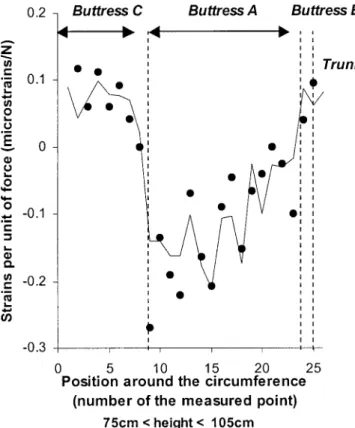
Model and experiment—Experimental patterns of strain
variations were compared with the model prediction. Linear
correlations between experimental values (
«
L/F) and
theoreti-cal ones
«
L/E
LF, computed from the model and independently
measured geometrical data, were calculated for different
sam-ples (by splitting the whole set of data into different zones)
(Table 1). In a general sense, the model and experimental
val-ues fit well, with an estimation of the mean modulus of
elas-ticity of 16 400 MPa, with no significant difference between
tension and compression. An example of the evolution of both
modeled and experimental strains around the circumference at
a given height is given in Fig. 8. However, the correlation
coefficient and the modulus of elasticity fit for each cross
sec-tion increase with height (Table 1). Without great changes of
modulus of elasticity from the buttress top to the base, the
model does not properly describe developments of strains with
height, as indicated by the observed bias on regressions split
by ridge or trunk positions. On the same longitudinal line,
theoretical strains decrease continuously from the top to the
base and measured ones are almost constant.
Wood properties—Measured wood basic density and
Young’s modulus in buttresses reached the mean value of 0.80
g/cm
3(CV 5%) and 22 160 MPa (CV 35.3%), respectively.
Fig. 8. Variations around the cross section of measured (circles) and mod-eled (solid line) values of strains due to bending of Sloanea cf. tuerckeimii. Example of height 90 cm, for buttress A in compression. Abscissa are the order of measured points around the cross section. The modulus of elasticity used in the simulation is the mean value for all the measured points (see Table 1).
Fig. 9. Variations of wood basic density and Young’s modulus measured on wood specimen within buttress A of Sloanea cf. tuerckeimii. Basic density is the ratio of oven-dried mass vs. green volume. Young’s modulus has been measured by tensile tests on air-dried wood.
density is 22 550 MPa for air-dried wood. Therefore, the
Young’s modulus of green wood was expected to be 16 180
MPa (value calculated from measured Young’s modulus of
air-dried wood) or 16 460 MPa (value calculated from density
measurements). In two-factor ANOVA, basic density varied
significantly with both height and radial position with a strong
interaction (P
, 0.001 for each effect, Fig. 9). Patterns of
variations were not regular with respect to height, neither for
the mean values nor ridge values. For Young’s modulus,
var-iations with depth were not significant. Very high values were
measured in upper parts, with no significant variations below
100 cm (Fig. 9).
DISCUSSION
Linearity, elasticity, and small strains—As we applied
small strains, the structural behavior remained linear and
elas-tic without any buckling on compressed sides. This is a
con-venient means of nondestructively measuring strains
every-where by reversible tests and will provide general information
about failure risks. However, with this approach, we could not
study accurately the modes and localization of failure, except
during the breakage experiment on the second tree. Neither
could we measure the nonlinear processes that lead to failure.
Modeled and experimental values of longitudinal strains—
In a general sense, the model and experimental values fit well.
The estimations of the mean green wood Young’s modulus
(16 400 MPa), when all data were pooled, seemed very
real-istic, when compared to independent values estimated from
tensile tests on air-dried wood specimens or from wood
den-sity, although we neglected bark that was very thin compared
to stem diameter. The model predicted well the evolution of
strains around a circumference (cross section level) and could
be used to analyze, for instance, the effect of different force
azimuths. However, without great changes of modulus of
elas-ticity from the buttress top to the base, the model did not
describe properly the evolution of strains with height. As such
variations were not observed from tensile tests or density
mea-surements on wood specimen, these great and regular changes
of E
Lwere not realistic, neither on the whole cross section
regardless of the radial position, nor on the ridges that would
contribute most to flexural stiffness. The odds are that some
hypotheses of the model are not robust enough, especially for
low and continuous taper and vertical fibers. Such results
em-phasize the capacities and limits of beam models that are often
used in plant biomechanical theoretical studies (Niklas, 1992)
and scarcely validated by direct assessment of strains and
stresses.
Stresses and strains with respect to failure risks—Strains
and stresses are three-dimensional. In the principal axes of
wood (L, fiber direction; T, tangential direction), at the trunk
surface, assuming linear wood behavior, stress components are
related to strain components:
s 5 E (« 1 n « )/(1 2 n n )
L L L TL T TL LT(a)
s 5 E (« 1 n « )/(1 2 n n )
T T T LT L TL LT(b)
s 5 2G «
L LT LTwhere E
Land E
Tare moduli of elasticity in L and T directions,
n
LTand
n
TLare Poisson’s ratios, and is the G
LTshear modulus
in LT plane (Guitard, 1987; Niklas, 1992). Because we
mea-sured
«
Tand
«
Lstrains of the same order of magnitude, and
as
n
TLK 1 (
n
TLø 20.03 [Niklas, 1992]), «
Thas no significant
effect on
s
Lin Eq. a, which then becomes
s ø E « (1 2 n n ) ø E «
L L L TL LT L LThus, Eq. 2 (see Appendix), implicitly assumed by other
au-thors (e.g., Ennos, 1995), is verified and wood follows
ap-proximately a simple one-dimension Hooke’s law in the
lon-gitudinal direction.
However, values of tangential stress
s
T, often neglected,
could be of great importance as wood is very weak when
submitted to tangential tensile stresses. When tangential
stress-es are zero, the ratio
«
T/
«
Lis
2n
LT, and
n
LTø 0.67 (Guitard,
1987; Niklas, 1992). Statistical correlation between
«
Tand
«
Lwas significant, with a ratio
«
T/
«
Lof
20.64. Thus, mean
tan-gential stresses
s
Tare proved to be statistically near zero. They
are tensile for points above the regression line
«
T/
«
L5 2n
LTand compressive for points below. For example, sides of
but-tress A are on average put into tangential tension during the
first set of tests. Tangential stresses are more likely to be low
near the ridge where the relation
«
T/
«
L5 20.64 is the most
significant. They can be high on buttress sides where no
re-lation between
«
T/
«
Lhas been found. For example, in the
sec-ond tree, by substituting in Eq. b values of the measured ratio
«
T/
«
Lon the buttress side, we prove that
s
Tis safe in
com-pression on the convex side, but dangerous in tension on the
concave one. Indeed, this tangential tension, superposed on the
high shear, provoked the crack observed during breakage of
the tree (Fig. 8).
Mattheck’s theory—To analyze our data with respect to the
constant stress theory, we need to define stress, because the
stress field is defined by three components at the stem surface.
Then we must design a stress index, which is calculated from
these three components and able to predict locally the risks of
failure. The choice of such a failure criterion is still a vexing
problem in highly anisotropic materials (Berthelot, 1999):
Standards are maximal strain or stress criterions (each strain
or stress component is compared to a limit experimentally
de-termined by straight forward uni-axial tests); however,
addi-tional interactive criteria able to describe the material behavior
under complex triaxial loadings can be designed (Berthelot,
1999). Although Mattheck (Mattheck, 1990; Mattheck and
Prinz, 1991) used the interactive Von Mises’ criterion, we
pre-fer to use a simple maximal strain or stress criterion that was
implicitly used by other authors (Ennos, 1995; Crook et al.,
1997). Indeed, Von Mises’ criterion is not adapted to
aniso-tropic materials (Berthelot, 1999). For instance, it predicts the
same risk of failure for a tension of 10 MPa in the longitudinal
direction than in the tangential one, although it is well known
that the former is safe and the latter not. Therefore, in bending
experiments in which longitudinal normal stresses
s
L(tension
and compression along wood grain) are obviously greater, Von
Mises’ criterion focuses on these stresses and neglects other
components. Actually, along and near the ridges, where
s
Lwould be the only significant stress, Von Mises’ and maximal
stress criteria are similar. In this part of the buttress, we found
two very different patterns: the first tree follows the constant
stress law, but the second one is much more stressed at the
buttress top. Both behaviors have been reported (Ennos, 1995;
Crook et al., 1997). According to Mattheck’s theory, the first
tree buttress would have reached its morphologically
opti-mized steady state. The second tree is still optimizing its
but-tress form. However, such assertions should be demonstrated
and, as pointed out by Ennos (1995), Mattheck’s theory could
not be verified by static data without chronological
observa-tions of dynamic growth in natural or experimental condiobserva-tions.
The mechanism of strain perception that controls growth
lo-cally is still a puzzling question. Nevertheless, regardless of
adaptive theories, the different buttress shapes (plate or shell)
of the two trees can explain the different observed patterns of
strains, because in the second tree, the buttress base is almost
perpendicular to the bending plane.
Moreover, neglecting stress components other than
longi-tudinal ones is not relevant, because breakage modes are
ob-viously not simple compression cracks on the buttress ridges
where longitudinal stresses are the highest. In the studied trees,
the greatest risks of failure are related to shear and tangential
tensions, even though values of these stress components are
smaller than the longitudinal ones (wood is less stiff, but also
less strong in these strain modes). Although some authors
dis-cussed the mechanisms of transverse or shear strengthening in
trees (Mattheck, 1991), potential adaptations of tree growth in
respect to these strain or stress modes in buttresses have not
yet been studied. If, as often supposed, buttresses are
material-saving devices, selected for more anchorage stiffness and
strength with less volume and less physiological expenditure,
in an environment with intense biotic competition for light and
space, they have to deal with a mechanical trade-off between
minimizing uprooting on one hand and risks of shear and
tan-gential failure in the plates on the other hand. The ecological
question is then to estimate the importance of the second
con-straint: do buttresses fail at the plates? Obviously, the answer
will depend on site conditions such as soil types, on buttress
shapes, and ontogenetic stages of species.
LITERATURE CITED
BERTHELOT, J. M. 1999. Mate´riaux composites. Comportement me´canique et analyse des structures. Editions Tec & Doc, Paris, France.
BLACK, H. L.,ANDK. T. HARPER. 1979. The adaptive value of buttresses to tropical trees: additional hypotheses. Biotropica 11: 240.
CHAPMAN, C. A., L. KAUFMAN, ANDL. J. CHAPMAN. 1998. Buttress for-mation and directional stress experienced during critical phases of tree development. Journal of Tropical Ecology 14: 341–349.
CLAIR, B., J. RUELLE,ANDB. THIBAUT. 2003. Relationship between growth stresses, mechano-physical properties and proportion of fibres with ge-latinous layer in chestnut (Castanea sativa Mill.). Holzforschung 57(2): 189–195.
CROOK, M. J., A. R. ENNOS,ANDJ. R. BANKS. 1997. The function of buttress roots: a comparative study of the anchorage systems of buttressed (Aglaia
and Nephelium ramboutan species) and not-buttressed (Mallotus wrayi) tropical trees. Journal of Experimental Botany 48: 1703–1716. ENNOS, A. R. 1993. The function and formation of buttresses. Tree 8: 350–
351.
ENNOS, A. R. 1995. Development of buttresses in rainforest trees: the influ-ence of mechanical stress. In M. Coutts and J. Grace [eds.], Wind and trees, 293–301. Cambridge University Press, Cambridge, UK. FOURNIER, M., B. CHANSON, B. THIBAUT,ANDD. GUITARD. 1994. Mesures
des de´formations re´siduelles de croissance a` la surface des arbres en relation avec leur morphologie. Observations sur diffe´rentes espe`ces. An-nales des Sciences Forestie`res 51: 249–266.
GENTRY, A. H. 1993. A field guide for the families and genera of woody plants of North West South America (Colombia, Ecuador, Peru) with supplementary notes on herbaceous taxa. Conservation International, Washington, D.C., USA.
GUITARD, D. 1987. Me´canique du bois et composites, Cepadues Editions, Toulouse, France.
HALLE, F., R. A. A. OLDEMAN,ANDP. B. TOMLINSON. 1978. Tropical trees and forests. An architectural analysis. Springer Verlag, New York, New York, USA.
HOLLOWEL, T., P. BERRY, V. FUNK,ANDC. KELLOF. 2001. Preliminary check list of the plants of the Guiana Shield. Smithsonian Institution, Washing-ton, D.C., USA.
KAUFMAN, L. 1988. The role of developmental crises in the formation of buttresses: a unified hypothesis. Evolutionary Trends in Plants 2: 39–51. KOLLMAN, F. F. P.,ANDW. A. COTE. 1968. Principles of wood science and technology. I. Solid wood. Springer-Verlag, New York, New York, USA. MABBERLEY, D. J. 1997. The plant book. A portable dictionary of the
vas-cular plants. Cambridge University Press, Cambridge, UK.
MATTHECK, C. 1990. Design and growth rules for biological structures and their application to engineering. Fatigue and Fracture of Engineering Materials Structures 13: 535–550.
MATTHECK, C. 1991. Trees: the mechanical design. Springer Verlag, Heidel-berg, Germany.
MATTHECK, C.,ANDM. PRINZ. 1991. Buttress root: why they grow and what they are good for. Internal Report. Karlsruhe Nuclear Research Centre, Karlsruhe, Germany.
NIKLAS, K. J. 1992. Plant biomechanics: an engineering approach to plant form and function. University of Chicago Press, Chicago, Illinois, USA. RICHARDS, P. W. 1995. The tropical rainforest. Cambridge University Press,
Cambridge, UK.
YOUNG, T. P., ANDV. PERKOCHA. 1994. Treefalls, crown asymmetry, and buttresses. Journal of Ecology 82: 319–324.
APPENDIX
The beam model for longitudinal stress and strain assumes the following hypotheses:
i. The trunk is vertical, i.e., all the centers of mass of each cross section are aligned on a vertical line x. The taper is continuous and low. Wood grain (i.e., longitudinal direction of fibers) is everywhere approximately parallel to the vertical x. Clearly, the two last assumptions are best adhered to with higher cross sections and less developed buttresses. Trunk displace-ments remain small.
ii. An initial plane cross section remains straight during bending strains. Therefore, at each height x, longitudinal strains«L(x,y,z) within the cross
section (y and z are coordinates in a horizontal plane, y in the same vertical plane of the applied force F) are a function of only three unknown pa-rameters: one elongation«0(x) and two curvatures k1(x) and k2(x) as
« (x,y,z) 5 « (x) 1 k (x)y 1 k (x)zL 0 1 2 (1)
iii. The stress vs. strain in wood behavior can be simplified into:
s (x,y,z) 5 E (x,y,z)« (x,y,z)L L L (2)
Henceforth, the modulus of elasticity ELwill be assumed to be constant within
the cross section, but this assumption is easily modified if significant varia-tions of ELwith y or z are observed.
Following this, forces that act on each cross section (height x) during the tests are calculated as
N(x)5 2F sin u, M (x)z 5 F cos u(L 2 x), M (x)y 5 0 (3) where F is the applied force. L is the distance from the ground to the belt that attaches to the cable and thus, at height x, (L2 x) is the lever arm due to bending.u is the angle between F and the horizontal. N is the normal force (compression due to the vertical component of the force F), Mzand Myare,
respectively, the bending moments around z and y (i.e., the products of the horizontal components of the force F by the lever arm).
Using the strength of materials (Niklas, 1992; Berthelot, 1999),«0(x), k1(x)
and k2(x) can be calculated from Eqs. 1, 2, and 3 as
« (x) 5 2F sin(u)/[E (x)S(x)]0 L
2
k (x1 5 F cos(u)(L 2 x)/{E (x)[I (x) 2 I (x) /I (x)]}L z yz y
k (x)2 5 2k (x)I (x)/I1 yz y (4) where S(x), Iy, Iz(x), Iyz(x) are geometrical characteristics of the cross section:
the cross sectional area and the three components of the second moments of area. Hence,«L(x,y,z) can be calculated everywhere from Eqs. 4 and 1.