HAL Id: cea-02288891
https://hal-cea.archives-ouvertes.fr/cea-02288891
Submitted on 16 Sep 2019
HAL is a multi-disciplinary open access archive for the deposit and dissemination of sci-entific research documents, whether they are pub-lished or not. The documents may come from teaching and research institutions in France or abroad, or from public or private research centers.
L’archive ouverte pluridisciplinaire HAL, est destinée au dépôt et à la diffusion de documents scientifiques de niveau recherche, publiés ou non, émanant des établissements d’enseignement et de recherche français ou étrangers, des laboratoires publics ou privés.
monoblocks on the ITER divertor outer vertical target
J. Gunn, T. Hirai, Y. Corre, F. Escourbiac, A. Grosjean, R Pitts
To cite this version:
J. Gunn, T. Hirai, Y. Corre, F. Escourbiac, A. Grosjean, et al.. A study of planar toroidal-poloidal beveling of monoblocks on the ITER divertor outer vertical target. Nuclear Fusion Journal of Plasma Physics and Thermonuclear Fusion, 2019, �10.1088/1741-4326/ab4071�. �cea-02288891�
J. P. Gunn,1* T. Hirai,2 Y. Corre,1 F. Escourbiac,3 A. Grosjean,1 R. A. Pitts2
1
CEA, IRFM, F-13108 Saint-Paul-Lez-Durance, France.
2
ITER Organization, Route de Vinon-sur-Verdon, CS 90 046, 13067 St. Paul Lez Durance Cedex, France
*
Corresponding author e-mail: Jamie.Gunn@cea.fr
Abstract
The design of the monoblocks constituting the ITER divertor vertical targets comprises a simple toroidal (i.e. toroidally-facing) bevel of 0.5 mm in order to magnetically shadow poloidal (i.e. poloidally-running) leading edges, arising from radial misalignments between toroidally neighbouring blocks, from parallel heat loads between and during ELMs. Previous studies suggest that excessive heating of long toroidal edges could also occur, possibly leading to melting during ELMs. Furthermore, despite the toroidal bevel, tiny regions of the poloidal leading edges known as "optical hot spots", accessible along magnetic field lines through toroidal gaps, remain exposed to parallel heat flux from ELMs. The intense heat flux onto those optical hot spots could be large enough to trigger tungsten boiling. A possible solution at the outer vertical target is to implement a planar toroidal-poloidal bevel that would hide all poloidal and toroidal edges and eliminate the optical hot spot. It will be demonstrated that a reasonable "shallow" toroidal-poloidal bevel solution solves all these problems with minimal trade-offs, under the condition that monoblocks on neighbouring plasma-facing units be well aligned poloidally in order to prevent the appearance of exposed leading edges, meaning, in the worst case, a stepwise downward shift of each toroidally upstream plasma-facing unit by -2±2 mm with respect to their downstream neighbours. A more deeply beveled solution has also been studied that is immune to poloidal misalignments, but which comprises important trade-offs in terms of higher heat load to the main wetted surface, and excessive ELM heat loads onto the magnetically shadowed side of the toroidal gaps. Unfortunately, due the inclination of magnetic flux surfaces, the planar toroidal-poloidal beveling solution does not work at the inner vertical target, meaning that its application at the outer target alone leaves the inner toroidal gaps unprotected. This, together with the technologically challenging requirement for a high degree of poloidal alignment of toroidally neighbouring plasma-facing units, has led to a decision not to apply the poloidal-toroidal bevel solution on the ITER vertical targets.
1 Introduction
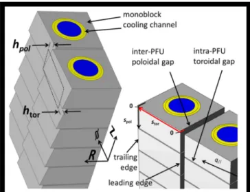
The ITER divertor targets will consist of plasma-facing units (PFU) made of pure tungsten monoblocks (MB) bonded to copper cooling channels [1]. This design, aimed at minimizing thermomechanical stress, introduces "intra-PFU toroidal gaps" (TG) as narrow as 0.4 mm between neighbouring MBs on a given PFU, and 0.5 mm "inter-PFU poloidal gaps" (PG) between neighbouring PFUs (Figure 1). The specified PFU assembly tolerance of ±0.3 mm normal to the nominal divertor surface results in poloidal leading edges (LE) that would be directly exposed to the parallel plasma heat flux at near perpendicular incidence. Bulk melting, which poses an unacceptably high risk for successful ITER operation, would be inevitable. Recent analysis [2] of MB heat loading by a simple ion orbit model showed that the magnetic shadowing provided by beveling the plasma-facing surfaces of MBs 0.5 mm in the toroidal direction should protect the poloidal LEs at the inter-PFU PGs from overheating due to steady state heat loads, while partially mitigating the risk of ELM-induced melting. Kinetic modelling including the self-consistent sheath electric field [3] and measurements [4] in the COMPASS tokamak have confirmed the physics of LE heating, and provide further justification for the decision to include a toroidal bevel at the high heat flux areas of the divertor vertical targets [5]. An unexpected prediction of [2] is that toroidal MB edges that are nearly parallel to the magnetic field could exceed allowable limits due to steady state heat loads and mitigated ELMs, even if those should avoid full melting of the principal plasma-facing surface. The heat deposition mechanism in intra-PFU TGs has been experimentally confirmed in the COMPASS tokamak [6] in a dedicated experiment designed to test the predictions. Furthermore, despite the toroidal bevel, tiny regions of the poloidal LEs known as "optical hot spots" (OHS), accessible along magnetic field lines through TGs, were identified [2]. The intense parallel heat flux from ELMs onto those optical hot spots could be large enough to trigger tungsten boiling.
Figure 1. Schematic of two neighbouring PFUs at the OVT. At left, with greatly exaggerated toroidal-poloidal planar beveling for illustration, the dashed rectangle represents the flat surface of a MB before beveling. The planar bevel is characterized by the depths htor in the
toroidal direction, and hpol in the poloidal
direction. At right, the poloidal and toroidal gaps, as well as leading and trailing edges are indicated, and the surface coordinates spol and stor along which
temperature profiles will be plotted throughout this paper are defined.
Within a Larmor radius of any plasma-facing surface in a tokamak, due to the removal of ions from the plasma, there is a poloidal ion flux directed in the ion diamagnetic direction (clockwise when looking in the toroidal direction, and when B×∇B is directed downward). At the ITER inner vertical target (IVT) (Figure 2), as shown previously [7], this ion flux strikes the lower TG edges due to Larmor gyration. The electron component of the heat flux, assuming that it can be described by the guiding center, or "optical" approximation
(the Larmor radius being negligibly small compared to the TG width), strikes the upper edge due to the inclination of the magnetic flux surfaces. It is therefore not possible at the IVT to protect one TG edge by a planar bevel in the poloidal direction (poloidal bevel) without sacrificing the other. At best, a better up-down equilibrium of the poloidal heat flux distribution could be sought. On the other hand, at the outer vertical target (OVT), both ion and electron fluxes strike the upper edges of the MBs (Figure 2). It is therefore feasible to protect simultaneously the short poloidal LEs and the long TG edges at the OVT by implementing a planar toroidal-poloidal bevel. The aim of this work is to find the optimal planar toroidal-poloidal bevel to avoid the toroidal edge heating and OHS problems at the OVT, recognizing that there is no possible solution for the IVT and therefore that TG gap overload, particularly during ELMs which are expected to load both targets at similar levels [8], will be a potential issue even if the problem can be solved at the OVT. It will be shown that such a solution does exist for the OVT, but its implementation in practice is either too onerous in terms of the requirements for component alignment or results in too high a penalty in terms of increased front surface steady state loading. It is for those reasons that the planar toroidal-poloidal bevel will not be implemented in ITER [8].
The modelling assumptions and the design criteria are detailed in Section 2. The reader who is not interested in the details of the analysis can skip, without loss, to Section 3 which summarizes the results. The Appendix contains analysis of the consequences of poloidal misalignment between neighouring PFUs.
Figure 2. Schematic illustration of an ITER divertor cassette. Due to their Larmor radii being comparable to the gap widths, ions (orbits shown in blue in the insets) strike the upper edges of OVT monoblocks and the lower edges of IVT monoblocks, whereas electrons, strike the upper edges at both targets due to the inclination of the magnetic flux surfaces (red curves). Electrons can be described under the guiding-center approximation, making their orbits equivalent to the red curves. This means that at the IVT, heat loading occurs at both edges of the TGs, whereas at the OVT, only the upper edges are affected. A poloidal bevel can only be effective at the OVT. At the IVT, there is no solution to simultaneously mitigate heating of both edges by poloidal beveling; trying to protect one edge only exposes the other to higher heat flux [7].
2 Modelling assumptions
For the reference simple toroidal bevel,
defines the minimum bevel depth htor for a given inter-PFU radial tolerance mPFU=±0.3 mm
and an additional margin δrad which is set to 0.2 mm. This is the origin of the choice of
htor=0.5 mm for the ITER vertical targets [9,10]. In the general case when poloidal alignment
mpol between neighbouring PFUs is not specified, the introduction of a poloidal bevel hpol
imposes a deepening of the toroidal bevel htor in order to guarantee poloidal LE protection.
Without poloidal alignment imposed, for example, TGs between PFUs are not aligned, and it is possible that the highest corner of the LE of a poloidally beveled MB be directly exposed to parallel heat flux downstream of the lowest corner of the preceding MB's trailing edge. With a poloidal bevel of depth hpol, therefore, the toroidal bevel depth must increase as
δ
(2)if the heat handling capabilities of the poloidal LE are not to be degraded with respect the reference single toroidal bevel. The beveling is illustrated in Figure 1.
The question is then how to define a design criterion to choose hpol. In Section 2.1, it
will be shown that geometrical arguments suffice to find a solution at the OVT, since both ion and electron components of the heat flux strike the upper TG edge, and thus they can be mitigated simultaneously. The analysis presented here consists of a series of dimensional scans for each toroidal-poloidal bevel combination. Plasma parameters of the 15 MA burning plasma scenario are adopted, and the ions are assigned a mass number of A=2.5 to approximately account for the mix of deuterium and tritium [2]. The magnetic field strength at the OVT is B=6 T for the nominal ITER toroidal field of BT=5.3 T at R=6.2 m. MBs
downstream of inter-PFU gaps are considered for inter-ELM (ion temperature Ti = 10 eV
ions) and ELM (Ti = 5 keV) heat loads. The assumed baseline, inter-ELM target heat flux is
taken as q⊥sym=15 MWm-2. This is defined in terms of a cylindrically symmetric divertor target, with no shaping or target tilting.
The global temperature field is calculated for the inter-ELM heat loads, while for ELM loading, the transient temperature spike is calculated on a local scale since the heat diffusion time is such that the peak surface temperature is reached when the heat pulse has diffused only ~0.15 mm into the bulk. For each of these cases (inter-ELM and ELM), scans of intra-PFU MB alignment, that is, variations of the radial step mrad and the TG width gMB between
neighbouring MBs on a given PFU are made. The range of the dimensional scan of gMB (±0.2
mm) exceeds the extremely tight specified assembly tolerance of the present ITER design (±0.1 mm). The scan of the tolerance to radial misalignment (±0.3 mm) is fully explored, even though, based on full scale prototype manufacturing, it is expected that better results will be obtained [11]. The misalignments analyzed here are listed in Table 1 (see Table 1 in [2] for the full set of specified tolerances). The worst case poloidal gap width (gPFU=0.7 mm)
between neighbouring PFUs is adopted, and they are assumed to be radially well aligned (mPFU=0). The latter is a simplifying assumption only, since the focus of this paper is on TGs.
As shown in [2], inter-PFU radial misalignment influences the toroidal wetted fraction for inter-ELM loads and poloidal LE heating during ELMs. The geometry is illustrated in Figure 3. Three measurement points are defined at each of the leading and trailing poloidal edges: one at each corner and one in the center.
Table 1. Values of intra-PFU gap width gMB and radial misalignment mrad, and inter-PFU gap width gPFU and
radial misalignment mPFU used in this study.1
gMB [mm] mrad [mm] gPFU [mm] mPFU [mm]
0.2 → 0.6 -0.3 → 0.3 0.7 0
Figure 3. (a) Illustration of the simulation geometry with definitions of intra-PFU and inter-PFU radial steps (mrad and mPFU respectively) and TG and PG widths (gMB and gPFU respectively). (b) Definition of
heat flux/temperature measurement points on the target MB#5 on which the heat loads are calculated as a function of shadowing by its five neighbours. TGu=upper or "upstream" toroidal gap edge; TOP=the principal exposed surface at the center of the trailing poloidal edge; TGd=lower or "downstream" toroidal gap edge; CRu=upper corner of the PG LE; PG=center of the leading poloidal edge; CRd=lower corner of the PG edge.
The simple finite difference thermal model developed in [2] is employed to calculate the MB temperature response to the specified inter-ELM heat loads. The MBs are treated as cuboids tilted in the toroidal and poloidal directions to obtain the same B-field incidence angle on the top surface as would be the case for real beveled MBs, and shifted relative to one another to simulate the radial steps arising from beveling. The error induced by this approximation has been quantified by comparison with finite element simulations of the true geometry using the commercial software package ANSYS (see Figure 4). Two inter-ELM cases are examined here as examples. In both cases the heat flux to the nominal axisymmetric target is taken to be q⊥sym=10 MW/m2 and is assumed to be purely convective (no radiation). The first is a simple toroidal bevel (htor=0.5 mm, hpol=0.0 mm) with q⊥shp=15.6 MW/m2
applied uniformly over the top surface except for the first 2 mm to simulate magnetic shadowing of the poloidal LE, and q⊥shp=20.8 MW/m2 on a 0.4 mm deep strip inside the TG to simulate toroidal edge loading. The second case is a “shallow” toroidal-poloidal bevel (htor=hpol=0.5 mm) with q⊥shp=16.1 MW/m2 applied uniformly over the top surface, again with
the first 2 mm shadowed, and no heat load inside the toroidal gap which is now protected by the additional poloidal bevel. The slightly higher top surface loading in comparison with the
1 In [2] the notation mrad was used to designate radial misalignment between any MB with respect to another,
whether it be on the same PFU or on a neighbouring one. In this paper it was felt necessary to differentiate radial misalignments between MBs on a given PFU (mrad) which is the main topic here, from radial misalignments
between neighbouring PFUs (here newly defined as mPFU). It would have been better to replace mrad by mMB for
example, to be consistent with the definition of gap widths (gPFU between PFUs, and gMB between MBs on a
first case is due to the additional slope due to the poloidal bevel. The total power integrated over the surface is roughly the same in both cases, respecting the conservation of magnetic flux tube cross-sectional area.
Figure 4. Comparison of the simple finite difference model (full curves) with finite element simulations (dashed) of the true geometry for (a) a simple toroidal bevel and (b) a shallow toroidal-poloidal bevel. In (a) the temperature is shown along the upper (blue curves) and lower (red curves) TG edges. In (b), the upper and lower edge temperatures are equal in the simple model (black curve), while for the ANSYS simulation the upper (blue curve) and lower (red curve) edge temperatures are shown. The toroidal distance along the TG edge is designated stor.
Both simulations find that the upper edge is 200°C hotter than the lower edge due to TG loading in the case of the simple toroidal bevel (Figure 4a). For the shallow toroidal-poloidal bevel with toroidal-poloidally uniform heat loading on the top surface, the simple model finds identical temperatures at the edges by symmetry. The finite element model of the full geometry yields slightly lower temperature at the upper edge. This is due to the shorter distance between the top surface and the cooling channel associated with the poloidal bevel (5.25 mm as opposed to 5.75 mm). The absolute values of temperatures calculated by the two models agree to better than 5% along the toroidal profiles, more than justifying the use of the simple model for scoping studies.
2.1 Design criterion for the toroidal-poloidal bevel
At the OVT, assuming as a design criterion full optical shadowing of the TG edge in order to prevent electrons from striking it during ELMs, the minimum poloidal bevel depth is given by the local flux surface inclination and the intra-PFU radial alignment mrad between
poloidally adjacent MBs
≳ ∆ ⁄
∥
(3) which depends on the toroidal bevel depth. The angles θ⊥ and θ// describe the magnetic field
incidence with the target (see detailed definitions in Section 2.2 of [2]), ∆θ=0.5° is the global OVT tilt angle (required to protect against radial misalignments between neighbouring cassettes [1]), and L=28 mm is the toroidal length of the MBs. The two bevel depths are coupled due to the fact that increasing toroidal bevel results in deeper penetration of the magnetic field lines into the TG (Figure 5). Note that when the TG edge is shadowed, the OHS is eliminated (see Section 3.4.3 in [2]). Combining Eqs. (2) and (3), the minimum toroidal bevel depth is
∆ ⁄ ∥
δ
1 ⁄ ∥ . (4)
Taking gMB=0.5 mm, mPFU=0.3 mm, mrad=0.1 mm, δrad=0.2 mm, θ⊥=2.7°, θ//=5.6°,
and ∆θ=0.5°, the optimal toroidal and poloidal bevel depths at the OVT are htor=1.1 mm and
hpol=0.6 mm. Such deep beveling would lead to an optical heat flux on the top surface
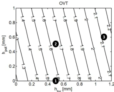
q⊥shp/q⊥sym=2.1, about twice higher than that to an ideal, axisymmetric vertical target (VT). The main culprit responsible for increasing the angle of incidence of the magnetic field lines is the toroidal bevel depth, due to the dominance of the toroidal component of the magnetic field (toroidal beveling rotates the MB surface away from it, whereas poloidal beveling only rotates the surface around it). The poloidal bevel increases the heat flux only slightly. The geometric heat flux enhancement factor is shown in Figure 6 for a range of toroidal and poloidal bevel depths. The decision as to what bevel depths are acceptable must evidently take into account the increased heat load at particular locations. Any heat load increase resulting from MB shaping implies a reduction of the maximum allowed stationary heat flux transported to the VTs, impacting the entire operational domain of ITER [8].
Figure 5. Schematic illustration of why toroidal beveling leads to deeper penetration of magnetic field lines into TGs. The upper diagram represents the frontal view of two MBs on a divertor vertical target separated by a TG. The magnetic field line (red arrow) grazes the lower edge of the upper MB at the position indicated by the dashed line, crosses the TG, and strikes the lower MB at its trailing edge. The lower diagram shows the view along the cooling pipe for the case of (1) an unshaped MB and (2) a toroidally beveled MB.
If it were feasible to impose an inter-PFU poloidal alignment to guarantee that the higher MB corner never be optically exposed, the toroidal and poloidal bevel depths could be decoupled. For example, the toroidal bevel htor=0.5 mm could be maintained, and a poloidal
bevel hpol=0.5 mm [Eq. (3)] would be sufficient to shadow the TG edge. In that case the heat
load to the top surface would only be enhanced by the factor q⊥shp/q⊥sym=1.64, as compared to
q⊥shp/q⊥sym=1.56 for the simple toroidal bevel. The consequences of poloidal inter-PFU misalignment are discussed in the Appendix.
In the following analysis three geometries will be studied. The first is the reference simple toroidal bevel (htor=0.5 mm, hpol=0.0 mm). The second is the “shallow”
toroidal-poloidal bevel (htor=0.5 mm, hpol=0.5 mm) referred to above. The third is a deeper
toroidal-poloidal bevel variant (htor=1.1 mm, hpol=0.6 mm), discussed above as the optimum solution
for complete shadowing of the TGs and the OHS even if inter-PFU poloidal MB alignment is not provided. This will be henceforth referred to as the “deep” toroidal-poloidal bevel.
Figure 6. Relative increase of heat flux to MB top surfaces as a function of toroidal and poloidal bevels assuming VT tilting angle ∆θ=0.5°. Numbered circles indicate (1) the reference simple toroidal bevel, (2) the shallow and (3) the deep toroidal-poloidal bevels examined in this paper.
Before focusing on the three specific geometries (reference toroidal bevel, shallow and deep toroidal-poloidal bevels) it is worth testing the simple geometric criterion of Eq. (4) for choosing hpol. Two dimensional ion orbit simulations were performed for a range of bevel
depths assuming both mrad=0.1 mm as a realistic case based on feedback from industry
concerning what has been achieved to date on full scale prototype PFUs [11], and mrad=0.3
mm which is the formally specified radial intra-PFU tolerance in the present design (2D simulations are sufficient for calculating the TG heat loading over most of the MB toroidal length, far from the poloidal LE). If a toroidal-poloidal bevel solution were to be implemented in ITER, it might be difficult to guarantee the 0.1 mm assembly tolerance because each MB would have to be machined individually before sliding it onto the cooling tube, as opposed to the pure toroidal bevel for which the simultaneous machining of all the MBs is foreseen before and/or after assembly. That is the reason why results for a "realistic" industry tolerance based on recent mock-up results and the more "pessimistic" tolerance are presented here.
Following the procedure detailed in Section 6 of [2], the normalized temperature increase resulting from ELMs (that is, the temperature increase with respect to that at the top surface of an ideal, axisymmetric target for a given ELM energy fluence) at the upper and lower TG edges of OVT MBs was calculated as a function of htor and hpol assuming mrad=0.1
mm (Figure 7) and mrad=0.3 mm (Figure 8). In both cases, the upper TG edge temperature
rises to about twice the reference temperature when full edge shadowing is marginally achieved. The poloidal bevel needed to achieve this shadowing is naturally deeper when the radial intra-PFU MB tolerance is relaxed from mrad=0.1 mm to mrad=0.3 mm.
Figure 7. TG edge temperature increase during an ELM with respect to the increase at an ideal axisymmetric target as a function of toroidal and poloidal bevel depths at OVT upper (left panel) and lower (right panel) edges assuming VT tilting angle ∆θ=0.5° and intra-PFU radial misalignment of mrad=0.1 mm. The dashed line on the
left panel indicates the poloidal bevel depth for which total magnetic shadowing of the TG edge is achieved.
Figure 8. As in Figure 7 now with mrad=0.3 mm.
The analysis of edge heating until now has focused on the excess with respect to an ideal axisymmetric surface. Another way to express the results is to evaluate how much the edge heats up with respect to the real top surface, independently of the acceptability of the latter. The data of the two previous figures are redisplayed in Figure 9 and Figure 10 normalized to the heat flux to the top surface, with the idea that if a certain top surface heat load can be accepted, then the associated edge heating can be accepted if it is equivalent.
Figure 9. TG edge temperature increase during an ELM with respect to the increase at the top surface (including MB beveling and VT tilting) as a function of toroidal and poloidal bevel depths at OVT upper (left panel) and lower (right panel) edges assuming intra-PFU radial misalignment of mrad=0.1 mm. The dashed line on the left
panel indicates the poloidal bevel depth for which total magnetic shadowing of the TG edge is achieved.
Figure 10. As in Figure 9 now with mrad=0.3 mm.
The upper toroidal edge heating is about the same as that of the top surface when the poloidal bevel achieves magnetic shadowing of the edge, confirming the intuitive criterion for the choice of hpol (the dashed red line in each of the four previous figures). This happens
because of the absence of electron heating on the TG edge, and because the ion flux is reduced compared to the top surface far from the gap. That said, the lower toroidal edge receives 1.3 to 1.4 times higher ion heat flux than the unperturbed top surface due to gyration of ions downstream of that edge. Returning to the three specific geometries defined earlier (for each of which the value of htor is dictated by the need to guarantee poloidal LE protection
depending on poloidal inter-PFU alignment), this is illustrated by the poloidal heat flux profiles in (Figure 11) and the ion orbits in the vicinity of TGs (Figure 12).
Figure 11. Poloidal profiles along an OVT MB (assuming worst case misalignment with respect to its neighbours, see Table 1) of ion (blue curves) and electron (red curves) ELM heat flux for the reference simple toroidal bevel (left panel), shallow toroidal-poloidal bevel (middle panel), and the deep toroidal-poloidal bevel (right panel). The surface coordinate spol runs from inside the upper TG poloidally down the MB to the lower
TG. The upper MB edge is at spol=0 and the lower edge is at spol=12 mm (see Figure 1). Heat flux is expressed in
terms of that (q⊥sym) to a smooth, axisymmetric target with no shaping for given plasma parameters.
Figure 12. Ion orbits at the point of highest ELM heat load in the vicinity of a TG at the OVT illustrating how the ion load is transferred from (a) the upper edge (y=0) with simple toroidal beveling to (b) the lower edge (y=12 mm) with deep toroidal-poloidal beveling. The toroidal direction is into the page, the y-coordinate is parallel to the MB cooling tube axis and points downwards toward the bottom of the vacuum vessel, and z is the vertical target surface normal vector. The magenta line indicates the magnetic flux surface defining the depth of the wetted area in the vicinity of the upper TG edge, and it also indicates the path followed by guiding-center electrons. Worst case misalignment is assumed, i.e. mrad=0.3 mm and gMB=0.6 mm.
The simple criterion for choosing the poloidal bevel depth hpol has been validated for
the case of ELMs which in ITER will release pedestal ions having Larmor radii up to 2 mm onto the divertor, and which cannot be modelled by the optical approximation used to define the criterion. This is perhaps coincidental, but is at least partly related to the fact that the electrons are modelled by the guiding-center (optical) approximation. Full 3D simulations of the thermal response due to steady state inter-ELM loads (Section 2.2) and transient response due to ELM loads (Section 2.3) will be detailed for the full range of tolerances on TG width
gMB and intra-PFU MB radial misalignment mrad.
2.2 Inter-ELM heat loads
The temperatures at the defined measurement points (see Figure 3b) after a 10 s exposure (chosen to be more than sufficient to allow the actively cooled MB to come to thermal equilibrium) to an inter-ELM heat load of q⊥sym=15 MW/m2 are shown in Figure 13 for the reference simple toroidal bevel. It should be noted that the extremely high temperatures seen in this figure are the result of simulating the maximum allowable heat flux to the divertor, (q⊥shp~20 MW/m2 to stay within the prescribed margin to critical heat flux). Avoidance by mitigation techniques which should make such occurrences very rare is a high priority for ITER operation. The temperature at the trailing (poloidal) edge (Figure 13a-c) varies with the penetration depth of field lines into the TG. Plotting all the upper and lower
TG edge temperatures against the field line penetration depth into the TG (Eq. 3) demonstrates that the upper edge temperature rise varies linearly with TG gap loading, as expected (Figure 14). Negative abscissa values correspond to full magnetic shadowing of the upper edge, and indeed the upper edge temperature decreases below the lower edge temperature. At the poloidal LE, for large values of radial and toroidal misalignment, the upper corner of the MB heats up due to the appearance of the OHS (Figure 13d), although consistent with the conclusions of [2], the temperature increase due to an intense but extremely localized point heat source remains modest. The poloidal LE far from gap crossings (Figure 13e) is cooler because it is magnetically shadowed. The lower corner temperature (Figure 13f) is nearly identical to that at the center of the LE because it receives essentially the same heat flux (the OHS appears on the upper corners when the PFUs are poloidally well-aligned, as assumed here, because the magnetic image of the preceding TG is projected downwards).
Figure 13. Steady state temperatures at OVT MBs having a simple toroidal bevel (htor=0.5 mm, hpol=0 mm) with
the intra-PFU MB alignments varied according to Table 1. The PFUs are poloidally aligned (mpol=0 mm). For
definition of measurement points see Figure 3.
Figure 14. Upper (black circles) and lower (red triangles) TG edge temperature as a function of field line penetration depth into the TG for a simple toroidal bevel (htor = 0.5,
Figure 15. Steady state temperatures at OVT MBs having a shallow toroidal-poloidal bevel (htor=0.5 mm,
hpol=0.5 mm) with the
intra-PFU MB alignments varied according to Table 1. The PFUs are poloidally aligned (mpol=0
mm). For definition of measurement points see Figure 3.
The equivalent calculations shown in Figure 13 for the simple toroidal bevel are compiled in Figure 15 for the shallow toroidal-poloidal bevel (htor=0.5 mm, hpol=0.5 mm). The
TOP temperature is only slightly (~50°C) higher than the simple toroidal bevel case because the B-field incidence angle is only slightly increased. The upper TG edge is about 300 °C cooler due to the suppression of the heat flux entering the gap. Nonetheless, for the largest radial misalignments mrad, the upper edge is slightly hotter than the top surface because the
poloidal bevel was optimized for mrad=0.1 and for larger values the upper edge is exposed. For
the smallest misalignments the reverse is true due to the shadowing. The poloidal LE temperature is about the same as the simple toroidal bevel case because the radial step from the toroidally upstream PFU is the same, which is thanks to the TGs between neighbouring PFUs being poloidally aligned. Now both the upper and lower corner temperatures are the same as the center of the LE because the optical hot spot has been eliminated.
To complement these results, spatial profiles of MB temperature along three toroidal and three poloidal cuts through the MBs are shown in Figure 16 for the "most reasonable" misalignment (gMB=0.5 mm, the present OVT design specification, and mrad=0.1 mm, the
typical misalignment reported by industrial full-scale PFU prototype manufacturing [11]). The slight global temperature increase at the top surface is more than compensated by the suppression of TG and OHS loading.
Figure 16. Steady state temperatures at OVT MBs having a simple toroidal bevel (htor=0.5 mm, hpol=0.0
mm): (a) Toroidal profiles at upper TG edge (blue curves), through the center of the MB (green curves), and at lower TG edge (red curves). (b) Poloidal profiles at poloidal LE (blue curves), through the center of the MB (green curves), and along the trailing poloidal edge (red curves). The same profiles are shown in (c,d) for a MB with toroidal-poloidal bevel (htor=0.5 mm, hpol=0.5 mm). In both cases gMB=0.5 mm and
mrad=0.1 mm. The PFUs are poloidally aligned (mpol=0 mm).
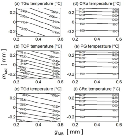
At first glance the shallow toroidal-poloidal bevel is promising, but only if inter-PFU poloidal alignment can be guaranteed. If it cannot, then deeper beveling is required. The thermal response of a deep toroidal-poloidal bevel (htor=1.1 mm, hpol=0.6 mm) is qualitatively
similar to that of the shallow bevel in that the TG loading (Figure 17a-c) is suppressed. The same holds at the LE (Figure 17d-f) due to elimination of the OHS. However, the top surface heat load increases by 30% with respect to the reference simple toroidal bevel case, which itself already increases the load compared to a perfectly aligned flat surface by roughly the same amount. This is the essential trade-off associated with the toroidal-poloidal bevel solution: edge and corner protection against increased main surface loading.
Figure 17. Steady state temperatures at OVT MBs having a deep toroidal-poloidal bevel (htor=1.1 mm, hpol=0.6 mm)
with the intra-PFU MB alignments varied according to Table 1. The PFUs are poloidally aligned (mpol=0 mm). For
definition of measurement points see Figure 3.
2.3 ELM heat loads
As introduced at the beginning of Section 2, in the case of transient ELM heat loads the thermal response is expressed as the peak temperature during the heat pulse, normalized by the peak temperature that would occur on an ideal axisymmetric target (see Eq. 34 in [2]). In the case of the reference simple toroidal bevel, the upper TG edge is hit hard by electrons and ions, the latter of which are strongly focused onto the top of the TG due to their Larmor gyration (Figure 18a), except when the MB is recessed (mrad<0) and the edge becomes
magnetically shadowed. At the magnetically wetted top surface (Figure 18b), far from TGs or the magnetic shadow, the heat flux depends only on the local magnetic field angle and not on the TG gap dimensions. The lower TG edge (Figure 18c) receives more heat flux than the top surface due to the gyration of ions over the poloidally downstream MB, and this kinetic effect increases with radial misalignment. The upper corner (Figure 18d) suffers from direct irradiation of the OHS by an electron beam penetrating through the TG between the MBs of the upstream PFU. For the largest ELMs expected in ITER, such high heat flux could lead to tungsten boiling [12]. The poloidal LE (Figure 18e), even though it is shadowed, is struck by ions which gyrate into the PG due to their large Larmor radii (~2 mm). The PG ELM heat flux is negligible for the deepest radial steps, suggesting a beneficial result of incorporating a deeper toroidal bevel (or equivalently, imposing a greater margin δrad), even though that
would be at the expense of higher main wetted surface loads. The lower corner (Figure 18f) behaves like the rest of the poloidal LE far from the OHS.
Figure 18. Transient ELM temperature spike (normalized to that of an ideal axisymmetric surface) at OVT MBs having a simple toroidal bevel (htor=0.5 mm, hpol=0
mm) with the intra-PFU MB alignments varied according to Table 1. The PFUs are poloidally aligned (mpol=0
mm). For definition of measurement points see Figure 3.
The shallow toroidal-poloidal bevel (htor=0.5mm, hpol=0.5mm) eliminates the worst
problems encountered above for the simple toroidal bevel. The top surface (Figure 19b) receives slightly higher heat flux because the poloidal bevel results in larger B-field incidence angle. Remembering that the intra-PFU gap at the OVT is specified as gMB=0.4±0.1 mm in
the actual design, and that realistic radial misalignment is expected to be mrad=±0.1 mm rather
than mrad=±0.3 mm based on feedback from industry, it can be seen that the upper TG edge
heating is even lower than on the top surface thanks to magnetic shadowing of the electrons and a reduction of the ion flux (Figure 19a). The lower TG edge receives more flux than the previous case both due to the increased slope associated with the poloidal bevel, and greater accessibility of ions that gyrate over the poloidally downstream MB, due to the deeper radial step (Figure 19c). The poloidal LE behaves the same as previously because the radial inter-PFU step does not change (Figure 19e,f). The drastic heating of the upper corner has been eliminated and it is even cooler than the rest of the LE (Figure 19d).
Figure 19. Transient ELM temperature spike (normalized to that of an ideal axisymmetric surface) at OVT MBs having a shallow toroidal-poloidal bevel (htor=0.5 mm, hpol=0.5 mm)
with the intra-PFU MB alignments varied according to Table 1. The PFUs are poloidally aligned (mpol=0
mm). For definition of measurement points see Figure 3.
The deep bevel (Figure 20b), as for inter-ELM loads, increases the top surface heat load about 30% with respect to the simple bevel. The upper TG edge loading (Figure 20a) is adequately mitigated, although at the expense of increased loading of the lower edge (Figure 20c). The LE (Figure 20d-f) receives practically no heat flux due the deep radial step between PFUs.
Figure 20. Transient ELM temperature spike (normalized to that of an ideal axisymmetric surface) at OVT MBs having a deep toroidal-poloidal bevel (htor=1.1 mm,
hpol=0.6 mm) with the
intra-PFU MB alignments varied according to Table 1. The PFUs are poloidally aligned (mpol=0 mm). For definition of
measurement points see Figure 3.
3 Summary of 3D analysis of inter-ELM and ELM loading for the three shaping solutions under consideration
As a reminder to the reader who may have opted to skip the details in Section 2, the thermal response of three MB shaping solutions has been analyzed: the simple toroidal bevel that has been retained as the reference design for the ITER vertical divertor targets (toroidal bevel depth of 0.5 mm), a shallow toroidal-poloidal bevel with 0.5 mm beveling in each direction, and finally, a deep toroidal-poloidal bevel with toroidal bevel depth htor=1.1 mm
and poloidal bevel depth hpol=0.6 mm. The aim of poloidal beveling is to hide the long upper
toroidal edges of the monoblocks from direct irradiation by electrons, and to reduce the heat flux from ions that can still penetrate into the TGs due to their large Larmor radii. The shallow bevel solution only works if the TGs of neighbouring PFUs are well aligned poloidally, while the deeper bevel works independently of poloidal alignment.
For each of the three shaping variants, two types of heat loading were considered. First, the equilibrium temperature resulting from steady state, inter-ELM heat loading of
q⊥sym=15 MWm-2 was calculated, defined as being that onto an unshaped, cylindrically symmetric divertor target (the quantities q⊥sym and q⊥shp were written qtg and qsurf in [2], but
have been changed here to be consistent with [8]). This value was chosen based on the findings of Ref. [2] as being roughly the maximum allowable that provides a 1.4 margin against critical heat flux during slow transient reattachment events for the 6 mm W thickness now decided as the final design value for the ITER MBs. Recently, is has been more precisely concluded that the maximum allowable local surface heat flux should not exceed q⊥shp=20
MW/m2 [13]. Coincidentally, the surface heat flux for which critical heat flux to the cooling tube can occur (q⊥shp=28 MW/m2), leading to catastrophic failure, is also roughly that for which full surface melting is observed in high heat flux tests. The limit of 20 MW/m2 thus simultaneously provides a margin against critical heat flux and full surface melting. The
q⊥sym=15 MWm-2 used here leads to q⊥shp=23.4 MW/m2 for the simple toroidal bevel, making it higher than the allowed limit, and provides only a factor 1.2 margin against critical heat flux. The aim of this analysis is to provide qualitative comparison between the different shaping solutions, so the exact choice of q⊥sym should not be regarded as important. The steady state temperatures given here can be scaled linearly with heat flux to obtain the results for other loading conditions with reasonable accuracy.
The second type of heat loading is due to transient ELMs that deposit a large amount of energy onto the surface in a very short time. The peak temperatures at specific points on the MBs are normalized to that which would occur on an ideal, axisymmetric divertor surface with no gaps or shaping. This formulation allows estimates of edge and corner heating for a given ELM energy fluence ε⊥sym, or inversely, allows the calculation of the ELM energy
fluence that would result in a specific temperature spike. Solution of the 1D transient heat equation for a triangular ELM pulse on a semi-infinite domain provides a simple relation between the energy fluence and the temperature spike [2],
∆ /"#$% = 2150 ± 50 +,2./- /0 [°C/(MJ m⁄ )] 8 (5) where Z, A, and Ti are respectively the charge number, mass number, and temperature (in
keV) of the incident ELM ions. For example, assume that a MB temperature is initially 1000°C due to steady state heat loading, and the maximum allowed ELM energy fluence that avoids melting the upper toroidal edge of the reference simple toroidal bevel is to be estimated. For Z=1, A=2.5 (a 50/50 deuterium/tritium mixture), and Ti=5 keV the temperature
spike on an ideal axisymmetric surface would be ~2150°C/(MJ/m2) [Eq.(5)]. The upper edge (TGu in Table 2) heats up 5.5 times more than that. Therefore, the maximum allowed ELM energy fluence would be ε⊥sym =(3422°C-1000°C)/2150/5.5=0.2 MJ/m2. In the case of the
shallow toroidal-poloidal bevel, the upper edge heats up only 1.8 times more, increasing the allowed energy fluence to ε⊥sym =0.6 MJ/m2.
The introduction of toroidal and poloidal beveling, which steepens the angle of incidence of the magnetic field lines, increases the steady state and ELM heat loads at the top surface with respect to those onto an ideal, axisymmetric surface, which is itself an issue of concern. Despite that, Table 2 indicates which edge and corner temperatures exceed those of the top surface for the three shaping variants. The idea is that if the edge and corner temperatures do not exceed the top surface temperature (green colour) or do not exceed them by "too much" (yellow colour), then a given shaping solution could be deemed acceptable (if the top surface temperature increase could itself be accepted). Red colour indicates shaping solutions for which significant risks are incurred, and which must be mitigated. The numbers are extracted from the contour plots detailed in Sections 2.2 and 2.3. In this context, "worst case" intra-PFU misalignment refers to the official ITER specifications for target TG width
to the official intra-PFU MB radial misalignment of ±0.3 mm tolerance on mrad. Instead, for
the latter, the worst case intra-PFU MB radial misalignment is taken to be mrad ±0.1 mm,
which is realistically attainable based on first results from full-scale prototype manufacturing [11].
To assist in reading Table 2, consider, for example, the lower toroidal edge for the deep bevel case (TGd). For the steady state loads, the edge temperature is TTGd=2991°C while
TTOP=2966°C. The lower edge temperature exceeds the top surface temperature by 25°C, so
yellow is the appropriate colour according to the definition (not exceeding the top surface temperature by more than 100°C). For ELM loads, the temperature spike at the lower toroidal gap edge is 2.9, while at the top surface, it is 2.1. So again, yellow is the appropriate colour (red would be appropriate if the normalized temperature spike were to exceed 4.2).
Concerning inter-ELM loads, at the corners and center of the poloidal leading edge (CRu, PG, and CRd) the temperatures of the simple toroidal bevel and the shallow toroidal-poloidal bevel are roughly the same because the toroidal bevel depths are the same (0.5 mm). However, in the case of the deep toroidal bevel, the leading edge is about 500°C cooler due to better magnetic shadowing. At the trailing edge, the main surface loading (TOP and TGd) increases with deepening toroidal bevel, which is expected because the incidence angle of the magnetic field increases (see Figure 6). The temperature at the upper edge (TGu) which is 300°C hotter than the top surface in the reference case becomes lower than that of the main wetted surface for the cases with poloidal beveling, satisfying the design requirement. On the other hand, for the deep toroidal-poloidal bevel, the main surface temperature (~3000°C) is 20% higher than that of the other two cases (~2500°C). The surface heat load to the deep toroidal-poloidal bevel is 30% higher than to the reference simple toroidal bevel. That the temperature dependence on top surface heat flux is slightly less than linear reflects the fact that blackbody radiation starts to be important around ~3000°C.
Table 2. Temperatures during inter-ELM phases and normalized peak temperature spikes during ELMs at the six measurement points (defined in Figure 3) of each of the three reference shape designs of OVT MB for the worst case intra-PFU misalignments (gMB=0.5 mm, mrad=0.1 mm). Colour coding indicates how the result compares to
the main surface temperature (TTOP). For inter-ELM and ELM loads, respectively, green indicates temperature
not exceeding TTOP and ELM spike not exceeding ∆T/∆Ttg at the top surface; yellow indicates temperature not
exceeding TTOP by 100°C and ELM spike not exceeding ∆T/∆Ttg by more than a factor of 2; red indicates that the
previous conditions are violated. Recall: ∆Ttg is the temperature spike due to an ELM calculated for an ideal,
axisymmetric surface on the basis of the heat transport equation on a 1D semi-infinite domain (see [2] for details).
htor [mm] 0.5 0.5 1.1 0.5 0.5 1.1
hpol [mm] 0.0 0.5 0.6 0.0 0.5 0.6
load inter-ELM q⊥sym =15 MW/m2 for 10 s normalized ELM TGu 2720°C 2451°C 2437°C 5.5 1.8 2.1 TOP 2483°C 2536°C 2966°C 1.6 1.6 2.1 TGd 2449°C 2530°C 2991°C 1.8 2.2 2.9
CRu 1100°C 1071°C 596°C 3.7 0.3 0
CRd 1046°C 1100°C 607°C 1.4 1.8 0.1 Concerning ELM heat loads, the main effects of the shallow poloidal bevel are to eliminate the optical hot spot, and to strongly attenuate the upper edge heating (TGu) at the expense of a modest increase of the lower edge heating (TGd and CRd). The latter increase is an ion orbit effect illustrated in Figure 11 and Figure 12. However, these positive results depend on the MBs on neighbouring PFUs being well aligned poloidally. If they are not, exposed LEs can arise where strong melting may occur. Since the whole point of a toroidal bevel is to eliminate such edges, the shallow toroidal-poloidal bevel would therefore be a step backwards in the design if attention is not paid to poloidal inter-PFU alignment (calculations to determine the required poloidal alignment between PFUs can be found in the Appendix).
The deep bevel, which does not depend on poloidal alignment, also performs well in that it eliminates all ELM heating of the LE and brings the upper toroidal edge heating down to the same level as that of the top surface. However, the top surface heat loading itself increases to ~30% higher than that of the simple toroidal bevel, and the lower edge heating is no longer acceptable (50% higher than on the top surface). It can be noted that this lower edge heat load enhancement (factor 2.9) is nonetheless better than that of the upper edge in the case of the reference simple toroidal bevel, which exceeds ∆Ttg by a factor of 5.5 (though they can
both be judged excessive).
4 Conclusions
In order to complete and extend previous studies [2,7] a detailed investigation of monoblock shaping at the ITER outer target has been made for the reference design that includes a 0.5 mm simple toroidal bevel, and more complex planar toroidal-poloidal beveling. The motivation for the more complex shaping is to avoid overloading of toroidal gap edges identified in [2,7], particularly during ELM transients, and to eliminate optical hot spots arising due to penetration of electrons down the toroidal gaps. At the inner target, because of its inclination with respect to magnetic flux surfaces, plasma loading is shared between the two sides of the toroidal gaps, so a planar toroidal-poloidal bevel there is of no use. Electrons strike the upper toroidal edges and ions, due to their large gyroradii, strike the lower edges causing the edge temperature to exceed the main surface temperature by factor of two or higher during the ELM pulse. It was found [7] that implementing a poloidal bevel to shield the lower edge from ELM ions does mitigate the heat load. However, the upper edge is then more exposed to inter-ELM heating, and it absorbs the ELM ions that previously would have struck the lower edge of the poloidally upstream monoblock. Furthermore, the optical hot spot deepens, making the poloidal leading edge more vulnerable to ELM-induced damage. A single ELM can deliver enough energy fluence to the optical hot spot to exceed the boiling threshold of tungsten [12].
At the outer target, the flux surface inclination with respect to the target is opposite the inner, so ions and electrons both strike the upper monoblock edges. A planar toroidal-poloidal bevel has the potential to eliminate toroidal gap and optical hot spot heat loading there. A shallow toroidal-poloidal bevel of depth 0.5 mm in both directions provides better
overall heat handling capability, thanks to full shadowing of the upper toroidal edge. Edge heating of the order of a few 100°C during inter-ELM loads caused by plasma flow into the toroidal gaps is suppressed. During ELMs, the intense heating of the upper toroidal edges, which can result in temperature spikes up to three times that of the main wetted top surface on the reference simple toroidal bevel, is limited to values that do not exceed the top surface temperature. The shallow toroidal-poloidal bevel leads to negligible additional heating of the top surface. The mitigation of the upper edge ELM heating comes at the cost of increased heating of the lower edge, although the latter does not exceed 35% that of the top surface. Poloidal leading edge ELM heating is improved with respect to that encountered on the simple toroidal bevel in that the optical hot spot is eliminated.
The favourable thermal handling properties of the shallow toroidal-poloidal bevel can only be guaranteed by imposing some level of poloidal alignment between toroidally neighbouring plasma-facing units (poloidal rows of monoblocks bonded to a cooling tube). Specifically, it is shown in the Appendix that if upstream shadowing plasma-facing units are at worst shifted downwards by -2±2 mm with respect to their downstream neighbours, then the poloidal leading edge remains shadowed for all combinations of radial alignment and gap tolerances. Poloidal alignment between neighbouring plasma-facing units is not presently specified as a requirement in the ITER divertor design specification. For the design of outer target, in order to guarantee the absence of exposed leading edges by successive 2 mm poloidal shifts would imply introducing six new plasma-facing unit variants into the design.
In light of the issue of poloidal misalignments between plasma-facing units, a deep toroidal-poloidal bevel was also studied which guarantees poloidal leading edge shadowing in all cases, in addition to full upper toroidal edge shadowing and elimination of the optical hot spot. The toroidal bevel would have to be increased to at least 1.1 mm, with a poloidal bevel of at least 0.6 mm. This results in a significant increase of the magnetic field line angle with the top surface, with a concomitant increase of 30% in the heat flux with respect to the reference simple toroidal bevel design. ELM heating of the lower toroidal edges also increases to become about 50% higher than the top surface heating, which is nevertheless a substantial improvement over the simple toroidal bevel whose upper edges heat up more than 300% under the same conditions.
The question of which shaping to adopt boils down to choosing between the extreme ELM heating of the upper toroidal edges and the optical hot spot associated with the reference simple toroidal bevel, or increased main surface loading as a trade-off for mitigated edge heating and elimination of the optical hot spot if a toroidal-poloidal bevel were to be considered. Edge ELM heating remains within 50% of that of the top surface in all cases studied, rather than exceeding it by a factor two or three. Depending on the toroidal-poloidal bevel depth, poloidal alignment between plasma-facing units might have to be imposed, increasing the complexity of the design. As discussed in [8], a real concern regarding stationary loading is the possibility of divertor reattachment events, during which the top surface heat loading can rapidly increase to values even higher than the reference load assumed for the shaping study discussed in this paper. A deep toroidal-poloidal bevel at the outer target significantly reduces margin on the allowable power load excursion during such events. Moreover, since there is no shaping solution to remove ELM-induced edge overload
at the inner target, and given that ELM loads at both targets are expected to be similar [8], the deployment of a more refined shaping at the outer target, with all the additional manufacturing complexity that this implies, is difficult to justify. It has thus been decided [8], due in large part to the results reported here and in the companion paper [2], that the monoblock surfaces on the vertical targets of the first ITER divertor will be shaped only in the toroidal direction.
APPENDIX
While the calculations of heat loading of MBs with a shallow toroidal-poloidal bevel at the OVT indicate great improvement of their heat handling capability with minimal trade-offs, it has to be noted that perfect poloidal alignment of toroidally neighbouring PFUs was assumed. In reality, each PFU is assembled separately, and because of the tolerance buildup of the TG width, there is no way to ensure that MBs on two neighbouring PFUs will be aligned. An example of two PFUs with poloidal misalignments mpol between them is shown in
Figure 21. An upward shift of the shadowing PFU with respect to its downstream neighbour, corresponding to positive values of mpol, results in a long portion of the poloidal LE being
fully exposed to the parallel plasma flux, a situation which is totally unacceptable, since it defeats the whole aim of introducing a toroidal bevel. From the point of view of ELM loading, it is worse than having a tiny OHS somewhere on the LE. On the other hand, this example corresponds to worst case inter-PFU radial and toroidal misalignments. For other cases closer to the nominal radial step and gap width, such optical LE exposure is less likely to occur. Nonetheless, the margin of δrad is eroded, and greater ELM loading on the poloidal
LEs is to be expected. In the opposite case, when the upstream PFU is shifted poloidally downwards (mpol<0), there is a broad range over which no optical LE wetting occurs, although
the margin of δrad erodes progressively with increasing downward poloidal shift.
Figure 21. View along magnetic field lines of two OVT PFUs equipped with MBs having a toroidal-poloidal bevel (htor=0.5 mm, hpol=0.5
mm). The downstream PFU is misaligned radially by mPFU=0.3 mm and the poloidal gap
width is gPFU=0.7 mm (worst case). In the left
panel, the upstream PFU is shifted poloidally mpol=2 mm upward with respect to its
downstream neighbour. The exposed LE is coloured yellow. On the right, the upstream PFU is shifted poloidally mpol=-2 mm downward with
respect to its downstream neighbour.
The thermal response of the shallow bevel to inter-ELM heat load of q⊥sym =15 MW/m2 is shown in Figure 22. If the poloidal shift of the upstream, shadowing PFU is upward (mpol>0), the highest point (the lower corner) now constitutes a LE and is immediately
exposed to the full parallel flux. Over roughly 2 mm < mpol < 5 mm, melting occurs. If the
poloidal shift of the upstream PFU is downward, the highest point of the LE of each MB remains optically shadowed and the temperatures are fairly stable. To keep the lower corner temperature no higher than that of the top surface, an upward poloidal shift roughly in the range 0 < mpol < -4 mm is acceptable.
Figure 22. Temperature at OVT MBs with shallow toroidal-poloidal bevel (htor=0.5 mm,
hpol=0.5 mm) under inter-ELM
heat flux for the worst case inter-PFU alignment (gPFU=0.7 mm,
mPFU=0.3 mm) as a function of
poloidal misalignment mpol. For
definition of measurement points see Figure 3. When the upstream, shadowing PFU is shifted upward between 2 and 5 mm, melting of the optically-exposed LE in the vicinity of the lower corner will typically begin after ~2 s.
Since any poloidal shift will modify the local radial step between MB surfaces, the ELM loads must also be examined (Figure 23). The transient response to ELMs is qualitatively similar to inter-ELM loads. Again, poloidal alignments roughly in the range 0 <
mpol < -4 mm (a downward shift of the upstream PFU) preserve the power handling
capabilities of the shallow bevel during ELMs. There is thus a range of poloidal misalignment (say -2±2 mm) which is an order of magnitude more relaxed than the tolerances on gap width and radial step in the present design, and not much more severe than the expected tolerances (~±5 mm at the OVT).
Figure 23. Normalized ELM temperature spike (with respect to that of an ideal axisymmetric target surface) at OVT MBs with shallow toroidal-poloidal bevel (htor=0.5 mm, hpol=0.5 mm) for
the worst case inter-PFU alignment (gPFU=0.7 mm,
mPFU=0.3 mm) as a function of
poloidal misalignment mpol. For
definition of measurement points see Figure 3. Negative values of mpol correspond to an upward
shift of the PFU with respect to its upstream neighbour, and vice versa.
In the interests of validating the procedure of full optimization of the deep toroidal-poloidal bevel (htor=1.1 mm, hpol=0.6 mm), despite the likely unacceptable trade-offs of high
top surface loading from both inter-ELM and ELM loads, and the high ELM loading of the lower TG edge, the same scan of mpol has been performed. As predicted, the poloidal LE
remains much cooler than the top surface over the entire range of poloidal misalignment in response to inter-ELM (Figure 24) and ELM (Figure 25) loads.
Figure 24. Temperature at OVT MBs with deep toroidal-poloidal bevel (htor=1.1 mm, hpol=0.6
mm) under inter-ELM heat flux for the worst case inter-PFU alignment (gPFU=0.7 mm,
mPFU=0.3 mm) as a function of
poloidal misalignment mpol. For
definition of measurement points see Figure 3. Since the deep bevel hides the LE with a margin of at least δrad=0.2 mm for any
poloidal misalignment, the temperature of the LE is relatively stable and no melting occurs. Indeed, it remains much cooler than the main wetted top surface.
Figure 25. Normalized ELM temperature spike (with respect to that of an ideal axisymmetric target surface) at OVT MBs with deep toroidal-poloidal bevel (htor=1.1 mm, hpol=0.6 mm) for
the worst case inter-PFU alignment (gPFU=0.7 mm,
mPFU=0.3 mm) as a function of
poloidal misalignment mpol. For
definition of measurement points see Figure 3. Negative values of mpol correspond to an upward
shift of the PFU with respect to its upstream neighbour, and vice versa.
ACKNOWLEDGEMENTS - The authors would like to thank Sophie Carpentier-Chouchana and Emmanuelle Tsitrone for fruitful discussions.
DISCLAIMER - The views and opinions expressed herein do not necessarily reflect those of the ITER Organization. ITER is the nuclear facility INB 174.
FUNDING - This work was supported within the framework of a contract between the CEA and ITER, the SSA 66 - IO/SCT/17/4300001509 "Study on the tungsten monoblock shaping of the divertor targets for safe operation of the ITER machine."
References
[1] S. Carpentier –Chouchana, et al., Phys. Scr. T159, 014002 (2014). [2] J. P. Gunn, et al., Nucl. Fusion 57, 046025 (2017).
[3] M. Komm, et al., Nucl. Fusion 57, 126047 (2017).
[4] R. Dejarnac, et al., Nuclear Materials and Energy 19, 19 (2019). [5] R. A. Pitts, et al., Nuclear Materials and Energy 12, 60 (2017). [6] R. Dejarnac, et al., Nuclear Materials and Energy 19, 19 (2019). [7] J. P. Gunn, et al., Nuclear Materials and Energy 12, 75 (2017).
[8] R. Pitts, et al., "Physics basis for the first ITER tungsten divertor," Nuclear Materials and Energy (2019), doi: https://doi.org/10.1016/j.nme.2019.100696.
[9] T. Hirai, et al., Fusion Eng. Des. 88, 1798 (2013). [10] T. Hirai, et al., Fusion Eng. Des. 127, 66 (2018). [11] ITER Divertor Section, private communication (2018).
[12] A.V. Arzhannikov, et al., J. Nucl. Mater. 438, S677-S680 (2013).
[13] F. Escourbiac, et al., https://doi.org/10.1016/j.fusengdes.2019.03.094, in press, Fusion Eng. Des. (2019).