Publisher’s version / Version de l'éditeur:
Vous avez des questions? Nous pouvons vous aider. Pour communiquer directement avec un auteur, consultez la première page de la revue dans laquelle son article a été publié afin de trouver ses coordonnées. Si vous n’arrivez pas à les repérer, communiquez avec nous à PublicationsArchive-ArchivesPublications@nrc-cnrc.gc.ca.
Questions? Contact the NRC Publications Archive team at
PublicationsArchive-ArchivesPublications@nrc-cnrc.gc.ca. If you wish to email the authors directly, please see the first page of the publication for their contact information.
https://publications-cnrc.canada.ca/fra/droits
L’accès à ce site Web et l’utilisation de son contenu sont assujettis aux conditions présentées dans le site LISEZ CES CONDITIONS ATTENTIVEMENT AVANT D’UTILISER CE SITE WEB.
Research Report (National Research Council of Canada. Institute for Research in
Construction), 2004-04-01
READ THESE TERMS AND CONDITIONS CAREFULLY BEFORE USING THIS WEBSITE.
https://nrc-publications.canada.ca/eng/copyright
NRC Publications Archive Record / Notice des Archives des publications du CNRC : https://nrc-publications.canada.ca/eng/view/object/?id=c046abf8-2169-4d72-a84f-991e78f78c9d https://publications-cnrc.canada.ca/fra/voir/objet/?id=c046abf8-2169-4d72-a84f-991e78f78c9d
NRC Publications Archive
Archives des publications du CNRC
For the publisher’s version, please access the DOI link below./ Pour consulter la version de l’éditeur, utilisez le lien DOI ci-dessous.
https://doi.org/10.4224/20377205
Access and use of this website and the material on it are subject to the Terms and Conditions set forth at
Proceedings of the Joint NSC-NRC Workshop on Construction
Technologies, April 26-27, 2004, Taipei, Taiwan
Proceedings of the Joint NSC-NRC Workshop on
Construction Technologies
April 26-27, 2004, Taipei, Taiwan
IRC Research Report RR-192
Edited by:
Tzu-Kang Lin, Keh-Chyuan Tsai, Mike Swinton
RR-192
A version of this document is published in / Une version de ce document se trouve dans:
Proceedings of the Joint NSC-NRC Workshop on Construction Technologies
April 26-27, 2004, Taipei, Taiwan. National Center for Research on Earthquake Engineering
PREFACE
The Taiwan-Canada Coopertion Memorandum was signed by the National Science Council
(NSC) of Taiwan and the the National Research Council (NRC) of Canada under the auspices
of the Taipei Economy and Culture Organization (TECO) and Canadian Trade Office in
Taiwan (CTOT) in October, 1997. Since then, the interaction between both sides has been
enhanced through several bilateral cooperative programs on various science and technology
issues including nano-technology, quantum mechanics, bio-technology, and so forth. In the
meanwhile, the exchange of information and personnel has been promoted, and workshops in
different fields have also been jointly hosted by NSC and NRC under the scope of this
Memorandum.
This Joint NSC/NRC Workshop on Construction Technologies is one of the workshop series
organized by NSC and NRC. The Taiwan National Center for Research on Earthquake
Engineering (NCREE) was authorized by NSC to host this Workshop. Members from the
Institute for Research in Construction (IRC) of Canada and researchers into construction
technology from Taiwan have been invited to attend the Workshop. It aims at sharing the
state-of-the-art construction technologies from both sides, as well as strengthening our
ever-growing friendship. It will also create opportunities for exchanging research outcomes
and to accelerate bilateral cooperative research programs in the near future.
This volume of proceedings contains all the papers to be presented in the Joint NSC/NRC
Workshop. A total of 27 papers have been collected together, covering a wide spectrum of
research work in construction technologies, e.g. indoor environment, building envelope and
structure, fire risk management, etc.. In addition, a session of panel discussion has been
scheduled before the end of the Workshop to formulate bilateral collaborations and future
perspectives of both sides on this topic.
The organizers of the Workshop would like to thank all participants for their dedicated effort
and support. The Workshop was made possible by the financial support of the NSC of
Taiwan. To this, all participants of the Workshop express their sincere thanks and
appreciation.
Keh-Chyuan Tsai, Director, NCREE
Russ Thomas, Director, IRC
CONTENTS
Preface I
Contents III
Construction Materials and Structural Technologies at the Institute for Research
in Construction
Lyndon Mitchell
1
Production of Sintered Fine Sediment Lightweight Aggregate
Tsong Yen, How-Ji Chen, Yue-Lin Huang and Hsien-Sheng Peng11
Research on Seismic Retrofit and Rehabilitation of Reinforced Concrete Shear
Walls Using FRP Materials
S. Hiotakis, D.T. Lau and N. Londono
17
Seismic Retrofit Study of Rectangular RC Columns Lap Spliced at Plastic
Hinge Zone
K. C. Chang and S. P. Chang
27
A Neuor-FBG System for Structural Control
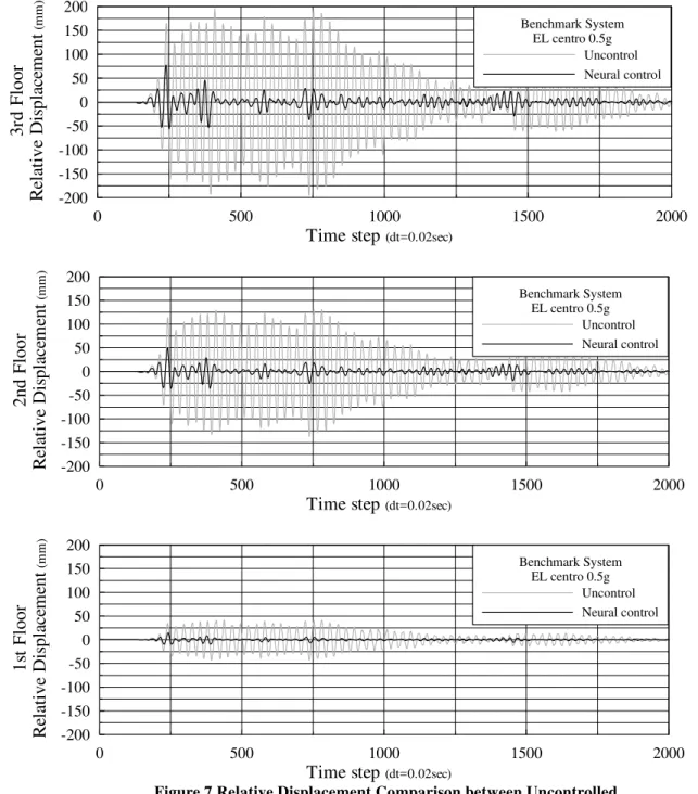
Tzu-Kang Lin, Kuo-Chun Chang and Zen Chang Chiu35
Reinforced Concrete Squat Walls Retrofitted with Carbon Fiber Reinforced
Polymer
Shyh-Jiann Hwang, Tsung-Chih Chiou and Yaw-Shen Tu
47
Condition Assessment of Structural Components Using Non-Destructive
Techniques
Gerry Pernica, Rock Glazer, Tareq Salloum, Gordon Chan, Tim Law and Allan Wiseman
57
Development and Application of Composite Materials Retrofit RC Structure
Technology in Taiwan
Fang-Yao Yeh and Kuo-Chun Chang
69
Earthquake Loss for Reinforced Concrete Building Structures Before and After
Fire Damage
Pai-Mei Liu, Yi-Hsuan Tu and Maw-Shyong Sheu
79
The Behavior of Reinforced Concrete Corner Columns under High Temperature
Wen-Chen Jau and Kuo-Li Huang89
Smoke Management Research at NRC
Gary LougheedAssessment of Fire Protection Performance of Water Mist Applied in Exhaust
Ducts for Semiconductor Fabrication Process
Yi-Liang Shu, Wei-Jin Jeng and Chiun-Hsun Chen
107
Smoke Management Design and Computer Simulation of an Underground
Mass Transit Station in Taiwan
Chi-Ji Lin and Yew Khoy Chuah
115
Sound Insulation Issues
John S. Bradle127
Sound Insulation of Double Skin Facade
Wei-Hwa Chiang, Yi-Nuo Chao, and Chi-Jeh Wu139
Properties of Vacuum Insulation Panels: Results from Experimental
Investigations at NRC Canada
M Kumar Kumaran, Phalguni Mukhopadhyaya, John C. Lackey, Nicole Normandin and David Van Reenen
147
Green Remodeling Program for Governmental Buildings
Lin Hsien-Te157
The Performance of Daylighting with Shading Device in Architecture Design
Chia-Peng Chou165
Investigation of Building Materials as VOC Sources in Indoor Air
Doyun Won and C.Y. Shaw173
The Current Status and Future Development of VOC Testing Lab for BPS in
Taiwan
C.M. Chiang, W.C. Shao and W. Long
181
Adapting and Assessing Energy Conversion Technologies for Integration in
Houses
Michael C. Swinton, Evgueniy Entchev, Mike Bell, John Gusdorf, Frank Szadkowski, Walter Kalbfleisch, Roger Marchand
187
A High Efficiency Single-Phase Three-Wire Photovoltaic Energy Conversion
System
J. F. Chen, T. J. Liang and Y. C. Kuo
195
Review on Building Energy Conservation Strategies and Recent Research
Programs in Taiwan
Kuan-Hsiung. Yang
203
An Overview on Research and Development of Building Fire Safety and
Establishment of Fire Testing Facilities in Taiwan
Chiang-Pi Hsiao, Chien-Jung Chen, Ming-Yuan Lei and Chen-Hung Lee
CONSTRUCTION MATERIALS AND STRUCTURAL TECHNOLOGIES AT THE
INSTITUTE FOR RESEARCH IN CONSTRUCTION
Lyndon MITCHELL1
ABSTRACT
A variety of projects and topics are under investigation within the cement-based materials group. The paper describes some important aspects of the work and then focuses on one project. The group has various tools and instruments to help achieve its goals. These include X-ray Diffraction (XRD), Scanning Electron Microscopy (SEM) and thermal analysis, they are briefly described. Quantitative phase analysis of cement using XRD using Rietveld analysis techniques will be discussed with emphasis on determination of amorphous content. The discussion concludes with suggestions for joint Taiwan-Canadian research projects, including the fire performance of high strength concrete and blended cements for climate change.
Keywords: Concrete, Materials & X-Ray Diffraction
INTRODUCTION
The study of cement and concrete science can be traced back to 1824 when J. Aspdin first manufactured modern Portland cement. In 1882 the famous French industrial scientist, Le Chatelier, published one of the first papers on its setting mechanism (Le Chatelier 1882). Since this paper the literature revolving around cement and concrete products has escalated exponentially, as has the production of Portland cement. Production has risen from 62.4 million tonnes in 1926 to 1.6 billion tonnes in 2000.
The Institute for Research in Construction (IRC) was established in 1947. Since that time the Institute has dedicated its work to safe and durable construction practises and concrete research has played a significant role. Early studies of concrete corrosion, in particular sulphate attack, led to the development of Type 50 cements (Mackenzie and Thorvaldson 1926; Swenson and Mackenzie 1968). Later work on alkali-aggregate reaction led to the first documented case of alkali-carbonate reaction (Swenson 1957), and advances in the knowledge of alkali-silica reaction (Grattan-Bellew 1987). This work still continues (Mitchell et al. 2004).
Previous work on the structure of CSH, the main binding phase of Portland cement, has lead to the publication of a structural model (Feldman and Sereda 1970).
More recent work has lead to the invention of conductive concrete (Pye et al. 2003) and the publication of several books (Ramachandran et al. 1981; Ramachandran et al. 2003; Ramachandran and Beaudoin 2000). Representatives from the materials group joined forces with the NRC’s conference services office and the Palais
de Congres de Montreal to successfully bid on the hosting of the 12th International Congress on the Chemistry
of Cement (ICCC). This congress will be held in Montreal, Canada, in July 2007.
1 Research Officer,Institute for Research in Construction, National Research Council Canada, email:Lyndon.Mitchell@nrc-cnrc.gc.ca
FACILITIES
The group has direct access to a variety of advanced and routine characterization techniques. A list of the major equipment operated by the group is given in table 1. This equipment would be utilized as part of an international collaboration or partnership. A successful international collaborative project will build on the complementary strengths of the partners.
Table 1. Table listing prominent equipment
Description Make and Model Comment
X-Ray Diffraction Scintag XDS 2000
(See figure 2) Cu K alpha Radiation
X-Ray Fluorescence Bruker AXS S4 Pioneer Analysis of elements C through to U
Thermal Gravimetric Analysis TA Instruments Q600
(See Figure 1) Up to 1500°C Simultaneous TGA/DTA
Scanning Electron Microscopy Hitachi S4800 Field Emission Gun electron source with
EDS. Resolution to a few nanometres Fourier Transfer Infrared
Spectroscopy Bomem MB100
Transmission, Photoacoustic, Attenuated total reflectance & solution spectroscopy
Atomic Force Microscopy Jeol JSPM 5200 Low temperature & vacuum stages
Rheometer Paar Physica MRC500 Low & High temperature vessels
The group, has a strong analytical base and access to both Institute and Council wide facilities. Cross-institute and council collaboration and co-operation is generally encouraged.
CURRENT PROJECTS NANOMATERIALS
The profile of nanotechnology is growing and promises to be a key area of cross disciplinary research over the next 20 years. Major capital investment for nanotechnology is being approved both here in Canada and around the world. The construction industry has been identified as a large potential market. This would appear to be a fruitful topic of collaboration.
IRC has initiated a multi-researcher project to develop new technologies and products for the construction industry based on nanotechnology, with an emphasis on cements, cement-based products, admixtures and concretes. Cement is the most widely used construction material, making concrete and cement nanotechnology particularly important to the industry. Initial research has focused on the synthesis and use of reactive/non-reactive nanoparticulates; Figure 3 shows nanoparticulate monocalcium aluminate synthesised using “Chimie Douce” methods (Mitchell et al. 2002; Mitchell et al. 2003). The roles of nanoparticles in cement binders, novel investigations into layered materials (Raki et al. 2004), and new approaches to concrete reinforcement (Makar and Beaudoin 2003) are also areas of current study.
Figure 1. TA Instruments Q600
Figure 2. Scintag XDS 2000
Figure 3. Nanoparticulate Monocalcium Aluminate Synthesised using “Chimie Douce” methods ALKALI AGGREGATE REACTION
Alkali-aggregate reaction is a chemical reaction between certain types of aggregates and hydroxyl ions (OH-) associated with alkalis in the cement (1998). Usually, the alkalis come from the Portland cement but they may also come from other ingredients in the concrete or from the environment. Under some conditions, the reaction may result in damaging expansion and cracking of the concrete. Concrete deterioration caused by alkali-aggregate reaction is generally slow, but progressive.
In Canada, cracking due to alkali-aggregate reaction generally becomes visible when the concrete is 5 to 10 years old. The cracks facilitate the entry of de-icing salt solutions that may cause corrosion of the reinforcing steel, thereby accelerating deterioration and weakening a structure.
The best method for preventing premature deterioration of concrete due to alkali-aggregate reaction is to use aggregates that have a proven history of good performance in concrete, or have been shown by laboratory testing to be non-problematic.
Another method for minimizing the potential for expansion due to alkali-silica reaction in concrete is to replace a portion of the portland cement with a supplementary cementing material. Low-lime fly ash, ground granulated
blast furnace slag, silica fume, metakaolin and natural pozzolans used in the appropriate quantities have been found to be an effective antidote for alkali-silica reaction.
In recent years much international effort has gone into demonstrating that the addition of lithium salts to concrete prevents or minimizes expansion due to alkali-silica reaction. Recent work at IRC has been aimed at investigating the mechanisms of this effect (Mitchell et al. 2004).
Figure 4. Opal after 28 days in Ca(OH)2 and KOH (2000x magnification)
Figure 5. Opal after 28 days in Ca(OH)2, KOH, and LiOH (2000x magnification)
Figure 4 shows the microstructure of opal (amorphous silica) after reaction with 1M potassium hydroxide for 28 days. Figure 5 shows the corresponding microstructure after reaction with 50:50 potassium hydroxide and lithium hydroxide. The particulate microstructure on reaction with potassium hydroxide is a smooth and rounded surface, with significant agglomeration. In contrast, the material reacted with blended potassium and lithium hydroxides appears to contain angular particles with a porous surface. This porous surface seems to inhibit agglomeration.
CLIMATE CHANGE & SUSTAINABILITY
As part of their five year strategic plan the IRC has created an initiative on sustainability. Sustainability has been defined by the World Commission on Environment and Development, (Brundtland Commission) 1987 as being “…..Development that meets the needs of the present without compromising the ability of future generations to meet their own needs……”
Many things we do affect the environment around us and it is impossible to construct a building without having some environmental impact on the world’s environment. So architects, engineers, owners and developers are shaping the future of our communities. They have a responsibility to design and select materials and systems that will provide a durable foundation for sustainable communities. Materials choice can make a major impact on green building design. A full-life cycle assessment (LCA) must be undertaken when determining which material to select. Consideration must be given to extraction, processing, transport, construction, operation, disposal, re-use, recycling, off-gassing and volatile organic compounds (VOC) associated with the material.
Every 1 tonne of cement produced, produces 1 tonne of CO2 (1998). For the year 2000, cement production
accounted for ~1.6 billion tonnes representing equivalent levels of CO2 by-product. Recently the climate change
and sustainability communities within the construction industry have been focusing on the use of supplementary cementing materials (SCM) as a means of reducing green house gas emissions. The principle behind use of
SCMs is that by replacing a fraction of the cement used in concrete with a SCM, a significant impact on CO2
production can be realised. The concrete sub-program is leading a technology transfer project to explain the benefits and hazards of using SCMs. The project will create a website, and is funded by the Government of Canada action plan 2000 on climate change.
The IRC is also leading a project called “The Laurier Tache Car Parking Garage Phase Two – The East Wing” to address some of these issues. The primary aim of this work is to develop and test new concrete technologies in the laboratory and then transfer that knowledge to the field. In parallel with the materials installation a sophisticated embedded instrumentation grid will also be installed. Monitoring over a 5-year period will commence with the collected data being incorporated into a life cycle analysis prediction tool.
Five types of sensors are to be installed at the Laurier-Taché Parking Garage.
Figure 6. Drawing S221 from the Harmer Podolak Specification document (66% submission). Phase 2 Level P1 of the Laurier Taché car parking garage
Sensor types:
1. Weldable strain gauges on reinforcement (movement within the steel)
2. Manganese Dioxide Reference Electrodes in proximity to reinforcement (corrosion of the steel) 3. Relative humidity and temperature sensors embedded in concrete
4. Vibrating wire strain gauges, embedded in concrete (movement within the concrete) 5. Vibrating wire strain gauges, surface mounted on concrete (movement within the structure)
The cabling for these sensors will be routed through metal conduit in line with the safety regulations enforced in the garage. They will then run along the ceiling of the structure to the datalogger.
A successful outcome to this project would be the creation of a life-cycle analysis model for high-volume fly ash concrete, and the adoption of this model by Public Works and Government Services Canada (PWGSC).
PWGSC manages the real estate assets of the Canadian Federal Government, and are the largest property-owner
in the world. The adoption of high-volume fly ash by this organisation would result in significant CO2 savings.
HEAVY METAL IMMOBILISATION
Most hazardous waste is disposed of in expensive, specialized landfill operations. Stabilisation of materials to make them suitable for conventional landfill is an option, but the use of waste materials that have been rendered safe in value-added products is very attractive. Most current hazardous waste recycling uses high temperature techniques, notably vitrification, that transforms waste into durable and environmentally safe products. Vitrification has many advantages, including high volume reduction, destruction of organic compounds, immobilization of a wide range of oxides, etc. However, it does have a number of limitations:
1. A general intolerance of glasses for sulphur and chlorine 2. limited solubility of some oxides
3. loss of volatile metals during processing 4. high processing costs
Alternative ceramic processing routes have been examined for the treatment of waste. Certain mineral structure-types are known to be resistant to leaching of heavy metals. Such geo-mimics can provide a matrix for high concentrations of toxic metals that are potentially stable over geological timescales. A related process is the use of zeolite materials to trap metal ions within an aluminosilicate matrix before reaction at low temperatures (40-60ºC) to produce an amorphous ‘geopolymer’ (Raki 2004). This approach is particularly well suited for volatile heavy metals such as lead and cadmium, that can be lost during high temperature processing. This project studies encapsulation of various metal ions in geopolymer materials, using natural alumino-silicates as reactants. The products are then studied using a variety of techniques to study the structure and stability of the geopolymer matrix to environmental degradation and leaching.
Collaborative project with Singapore
As part of an international collaboration with Singapore, the concrete subprogram will be working with researchers from the NRC’s Institute for Chemical Process and Environmental Technology (ICPET) to turn a hazardous waste into a usable construction product.
Disposal of garbage is a worldwide problem, and involves the use of methods such as landfills or incineration. In densely populated places where space is at a premium, incineration is often the most popular solution. In some cases, such as in Singapore, it is the only solution.
But, incineration does not mean complete waste elimination. Facilities are forced to deal with the substantial accumulation of fly ash, lightweight particles entrained in the gases released during burning. Fly ash, which collects in the flues of incinerator smoke stacks, is classified as a hazardous material because of the range of heavy metals it contains, making disposal difficult and expensive. Chances for safe disposal, and even reuse, are much more promising if the toxic metals can be trapped in stable synthetic "rock-like" materials made from other non-hazardous minerals also found in the fly ash. The NRC-Singapore research project will focus on creating these new materials.
The project, which will begin in the next few months is made possible through an Memorandum of Understanding (MOU) between NRC and the Agency of Science, Technology and Research of Singapore, known as A*Star. Under the agreement, both sides provide funding for joint collaborations. Over 10 different NRC research institutes are currently involved in research projects under the agreement, which commenced in 1997.
QUANTITATIVE PHASE ANALYSIS OF CEMENT
Powder diffraction techniques for the analysis of cements and cement clinkers have been used for many years (Taylor et al. 2002). The emergence of the Rietveld method as a practical tool for quantitative analysis has allowed the study of increasingly complex systems. The recent advent of convolution-based profile fitting has brought this powerful technique to the verge of being a routine analytical tool for cement quality control.
However, in common with the more common diffraction techniques, Rietveld analysis only yields information on the crystalline phases present in the material. The possibility of significant amorphous content in a cement or fly ash cannot be ruled out, and this material may have a profound effect on the physical and chemical properties, e.g. the glass content in fly ashes.
The Rietveld method may be used to determine amorphous content by spiking the sample with a known quantity of a standard material. The difference between the calculated and known quantity of the standard material yields the amorphous content. The approach has many potential problems with regard to technique and sample preparation, and its application to systems as complex as cements and clinkers has only recently been reported (Suherman et al. 2002; Whitfield and Mitchell 2003). The potential benefits in knowing the amorphous content of a material are numerous, and as such, it is therefore worth expending considerable effort in developing these techniques.
Evidence published in 1937 by Lerch and Brownmiller (Lerch and Brownmiller 1937), indicates that cement clinkers can contain significant amorphous contents up to ~28%. In the context of modern-day quenching of clinker by forced-air cooling, this should not be surprising. Lerch and Brownmiller obtained their results by careful and skilful use of calorimetric techniques that would be rarely found in the modern laboratory. A study using a standardless X-ray technique known as the Ruland method, described a large variability in amorphous content for laboratory-produced single cement-phases (Yang 1996). Another paper stated a value of 19% for
the amorphous content of monoclinic C3S using the Rietveld method (De La Torre et al. 2001).
A study was undertaken to apply the Rietveld method of determining amorphous content to clinkers and ultimately cements. The experimental procedures used are explained in Whitfield and Mitchell (2003). An example of the diffraction data and the fitting obtained using the Rietveld method is shown in Figure 7. The raw results for this sample and the derived results for the cement are shown in Table 2. They show an amorphous content of 18% for the cement, which is consistent with the results previously obtained (Lerch and Brownmiller 1937; Suherman et al. 2002).
In order to test the validity of the results, a number of samples were prepared with an additional spike of an amorphous slag, as well as samples known to be highly crystalline. The cements spiked with slag yielded results as expected given the previously calculated amorphous content of the unspiked cement, as shown in Table 3. In addition, the alumina sample analysed did indeed yield low amorphous content, as one would expect.
This work has demonstrated the feasibility of using advanced X-ray diffraction techniques to determine the amorphous content in materials as complex as cements and clinkers.
FUTURE RESEARCH
Potential projects of interest include 1) development of various intumescent coatings for fire protection of concrete structures and 2) blended cements for climate change.
The first project, the study of high strength concrete’s fire performance, would involve a number of IRC researchers and two programs: Building Envelope and Structure, and Fire-Risk Management. The project would involve designing concrete and concrete coatings for use in public areas, such as tunnels and subways. These types of structure require materials with non-toxic fire retarding properties to allow extended human evacuation times.
The second project will focus on making “green” construction products. The replacement of cement with supplementary cementing materials (SCMs), i.e. blended cements, within a mix is considered to be environmentally friendly from a climate change perspective. As the manufacture of one tonne of cement
produces one tonne of CO2, the replacement of 25-50% of the cement with SCMs can account for significant
greenhouse gas (GHG) savings. This project would investigate the potential of new supplementary materials and attempt to remediate more traditional ones such as poor quality fly ash. Remediation can be achieved either with the development of a new accelerating additive or by changing the composition of the supplementary material itself. This project would also involve several researchers, but would only involve the Building Envelope and Structure program.
Figure 7. Rietveld difference plot of a type 10 ordinary Portland cement with addition of a 25 wt% TiO2 spike (Whitfield and Mitchell 2003).
Table 2. Results of the analysis shown in figure 7 (Whitfield and Mitchell 2003).
Phase
Percentage
Corrected
Content
Rutile 25.6
C
3S 35.9 49.3
C
2S 7.8 10.8
C
4AF 2.0 2.8
C
3A 7.9 10.8
Anhydrite 0.7
0.9
Bassinite 1.7
2.4
Calcite 2.9 3.9
Gypsium 0.9
1.2
Amorphous 14.7
17.8
Total 100 100
Table 3. Calculated results for type 10 cements with and without a slag addition. The result of a analysis of a crystalline alumina sample additionally demonstrates that the method yields realistic results (Whitfield and Mitchell 2003).
Sample % Amorphous content
TYPE 10 CEMENT 17.8 ± 2.2
Type 10 cement with 12.7wt% slag
25.8 ± 2.1
(expected = 28.2% assuming 17.8% amorphous content for cement)
0.3mm polishing Al2O3 2.3 ± 2.3
CONCLUDING REMARKS
This paper is a brief overview of historical and ongoing work carried out by the Cement based materials Group at the Institute for Research in Construction. The paper documents some of the expertise and instrumental facilities available for collaborative projects. Two possible project areas have been suggested, but other proposals for collaborative research from the Taiwanese scientific community will be most welcome.
ACKNOLEDGEMENTS
The author would like to thank Dr’s Whitfield, Raki and Beaudoin for their useful discussion and reviews.
REFERENCES
De La Torre, A. G., Bruque, S., and Aranda, M. A. G. (2001), "Rietveld quantitative amorphous content analysis", Journal of Applied Crystallography, Vol. 34, 196-202.
Feldman, R. F., and Sereda, P. J. (1970), "The new model for hydrated Portland cement and its practical implications", Engineering Journal, Vol. 53, 53-57.
Grattan-Bellew, P.E. (1987), Concrete alkali-aggregate reactions : Proceedings of the 7th International
Conference, Ottawa, Canada, Noyes Publications, Park Ridge, N.J., USA
Lea's Chemistry of Cement and Concrete, (1988) Hewlett, P. C. (Ed), Arnold, London, UK
Le Chatelier, H. (1882), "Recherches expérimentales sur laconstitution des ciments et la théorie de leur prise (Experimental researches on the constitution of cement and the theory of their setting)", Acad.Sci.Paris, Vol. 94, 867-869.
Lerch, W., and Brownmiller, L. T. (1937), "Method for Approximating the Glass Content of Portland Cement Clinker", Journal of Research of the National Bureau of Standards, Vol. 18, 609-622.
Mackenzie, C. J., and Thorvaldson, T. (1926), "Differentiation of the Action of Acids, Alkali waters, and Frost on Normal Portland Cement Concrete", Engineering Journal, Vol. 9, 79
Makar, J. M., Beaudoin, J. J., (2003) "Carbon Nanotubes and their application in the construction industry", 1st International Symposium on Nanotechnology in Construction, Paisley Scotland UK
Mitchell, L. D., Beaudoin, J. J., and Grattan-Bellew, P. E. (2004), "The effects of lithium hydroxide solution on alkali silica reaction gels created with opal", Cement and Concrete Research, Vol. 34, 641-649.
Mitchell, L. D., Margeson, J., Beaudoin, J. J., (2003) "Synthesis and Characterization of Nanoparticulate Calcium Aluminates", 1st International Symposium on Nanotechnology in Construction , Paisley Scotland UK
Mitchell, L. D., Whitfield, P. S., Margeson, J., and Beaudoin, J. J. (2002), "Sucrose Synthesis of Nanoparticulate Alumina", Journal of Materials Science Letters, Vol. 21, 1773-1775.
Pye, G. B., Myers, R., Arnott, M. R., Beaudoin, J. J. and Tumidajski, P. J., (2003) Conductive Concrete Composition. US Patent. 6,503,318 .
Raki,L. (2004) Turning wastes into building materials. Construction Innovation. 9, (1):6
Raki, L., Beaudoin, J. J., and Mitchell, L. D. (2004), "Hydrotalcite-like Materials: Properties and uses in concrete", Cement and Concrete Research, Submitted
Ramachandran, V.S. and Beaudoin, J.J. (2000), Handbook of Analytic Techniques in Concrete Science and
Ramachandran, V.S. Feldman, R.F. and Beaudoin, J.J. (1981), Concrete Science, Heyden & Son Ltd, London, UK
Ramachandran, V.S. Paroli, R.M. Beaudoin, J.J. and Delgado, A.H. (2003), Handbook of Thermal Analysis of
Construction Materials, Noyes Publications/Williams Andrew, New York
Suherman, P. M., van Riessen, A., O'Connor, B., Bolton, D., and Fairhurst, H. (2002), "Determination of amorphous phase levels in Portland cement clinker", Powder Diffraction, Vol. 17, 178-185.
Swenson, E. G. (1957), "A Canadian Reactive Aggregate Undetected by ASTM tests", ASTM Bulletin, 48-51. Swenson, E. G., Mackenzie, C. J., (1968) "Contributions of Thorbergur Thorvaldson to cement and concrete
research. A historical review", E.G.Swenson (Ed), Performance of Concrete, pp. 3-17.
Taylor, J. C., Aldridge, L. P., Matulis, C. E., and Hinczak, I. (2002), "X-ray Powder Diffraction Analysis of Cements", In: Bensted, J., and Barnes, P. (Eds) , Structure and Performance of Cements, Spon Press, London
Whitfield, P. S., and Mitchell, L. D. (2003), "Quantitative Rietveld Analysis of the Amorphous Content in Cements and Clinkers", Journal of Materials Science, Vol. 38, 4415-4421.
Yang, R. (1996), "Crystallinity Determination of Pure Phases used as Standards for QXDA in Cement Chemistry", Cement and Concrete Research, Vol. 26, 1451-1461.
PRODUCTION OF SINTERED FINE SEDIMENT LIGHTWEIGHT AGGREGATE
Tsong YEN1, How-Ji CHEN2, Yue-Lin HUANG3 and Hsien-Sheng PENG4
ABSTRACT
Artificial lightweight aggregates are often produced by sintering clays, shales, slates and other materials. Processing fine sediments from a reservoir into lightweight aggregates is a new idea. The advantage of reusing fine sediments extends the lifespan of a reservoir and also solves a common environmental problem. This paper investigates the production process and mechanical properties of lightweight aggregates made from fine sediments collected from the Shih-Men Reservoir, Taiwan. Approximately 95% of the reservoir’s fine sediment particles will pass through a No.200 sieve. This
sediment is composed of 61% of SiO2, 18% of Al2O3, and 6.5% Fe2O3. These fine sediments have
the potential to be processed into lightweight aggregate. In this study, these fine sediments were
granulated and heated to the fusion point, about 1150℃, in a rotary kiln. When heated, the particles
became soft grew 50% to 200% larger than their original volume. In these experiments, the lightweight aggregates were sintered into a single nominal particle size (11 mm) and 3 specific weight ranges (0.8~1.0, 1.0~1.2, 1.2~1.4). The test results show that the original size of the fine sediment significantly affects the quality of the sintered lightweight aggregates. Using ultra-fine sediments as the raw material is advantageous in forming surface-glassed lightweight aggregates with reduced water absorption capacity and higher compressive strength. The water absorption adsorption capacity of the lightweight aggregates varied from 9% to 13%. The particle strength was between 7 MPa and 17 MPa. The test results indicate that fine sediment lightweight aggregate can serve as structural aggregate.
Keywords: fine sediment, lightweight aggregate, mechanical property.
INTRODUCTION
Lightweight aggregate concrete, manufactured using lightweight aggregates instead of traditional natural aggregates, possesses many advantages such as light weight, lower thermal conductivity, durability and better seismic resistance. Developed countries, including the European countries, the US and Japan, began to produce lightweight aggregates for use in structural engineering or non-structural purposes at the beginning of the Twentieth Century. Moreover, several countries have applied high performance lightweight concrete to the construction of long-span pre-stressed bridges in recent years (Bardhan-Roy 1995, Helgesen 1995, Ikeda 1995). There are 69 main reservoirs in Taiwan. All of these reservoirs have the same deposition problem. The total deposition quantity is up to 470 million cubic meters. This sediment deposition disrupts the flood prevention, water retention and electrical power generation capabilities of reservoirs and severely affects the ecological environment (Chen et al. 2003).
Researching and developing fine sediments as the primary materials for lightweight aggregates as effective way to transform a problem into an advantage and prevent environmental pollution. Aggregate production costs could be lowered, marketing competitiveness enhanced, and applications for new types of materials could be expanded. The proposed process could result in important economic value and social significance. For these reasons, this research investigated how the fine reservoir sediments could be sintered into lightweight aggregates.
1 Professor, Department of Civil Engineering, National Chung-Hsing University, Taiwan, e-mail: tyen@dragon.nchu.edu.tw 2 Professor, Department of Civil Engineering, National Chung-Hsing University, Taiwan, e-mail: hjchen@mail.ce.nchu.edu.tw 3
Professor, Department of Civil Engineering, National Chung-Hsing University, Taiwan, e-mail: ylhuang@dragon.nchu.edu.tw
SINTERING TECHNOLOGY OF ARTIFICIAL LIGHTWEIGHT AGGREGATES
The artificial lightweight aggregate sintering principle is similar to the sintering process used with semi-finished clay products, pottery or porcelain. The raw materials were preliminarily grained or shaped into molds to form powder. The powder was then manufactured into lightweight aggregates using heat treatment processes.
Sintering Theory
Under the high temperature sintering process, every specific mineral material has its inherent chemical heat reaction. These reactions make these products more stable. The structure of these products is extremely difficult to change using any other procedures.
The raw material used to manufacture lightweight aggregates is composed of powdered minerals. The firing and hardening procedure is generally called sintering. The sintering mechanism polymerizes the powder particles at the contact point, reducing the inseparable grain formed as the interval between the particles.
The greater the number of contact points, the faster the reactions occur. This indicates that the finer the powder particles, the higher the quality of the lightweight aggregates. Many other mechanisms exist in this process. The most important thing is that the products tend to become dense and tough because of polymerization process. There is a wide divergence between lightweight aggregates and ceramics. Lightweight aggregates exhibit a stiff glassed surface and internal cavities formed from heat expansion. Conversely, excessive expansion destroys the quality of ceramics.
Artificial Lightweight Aggregate Expansion Mechanism
Thermal expansion in the material is the most significant condition in the production of lightweight aggregates. There are two necessary requirements for the raw material to form and expand. The first requirement is glassed phase formation under high temperature with enough material adhesion to contain the expanding gases. The second requirement is that material components must exist that can discharge the gas when the glassed phase is formed. Thermal expansion under high temperature is the result of solid phase, liquid phase and gas phase dynamic equilibrium. Only when these two conditions are provided at the same time is it possible to produce homogenous, porous lightweight aggregates.
By investigating several expansible and non-expansible materials, how the adhesive strength of the plastic fluid
formed was verified. Higher temperature is needed to attain increased SiO2 and Al2O3 adhesion. CaO, MgO, FeO,
Fe2O3, K2O, Na2O and B2O3 are all fluxes, causing adhesion to decrease as their content in the material increases.
To improve and control the expansion process, the variation in the high temperature sintering gradient must not be too large.
The components that produce gases during heating are plentiful, such as organic matter, carbonates and water. These substances produce different gases under different temperatures.
In summary, the expansion behavior of lightweight aggregates is produced by multiple reactions and factors. The various raw material chemical or mineral compositions, apparatus, environmental conditions and parameters significantly affect the thermal expansion results in lightweight aggregates.
Artificial Lightweight Aggregate Sintering Procedure
The manufacturing process before sintering varies with the raw material type and its physical properties. The manufacturing processes can be distinguished into grained and non-grained types.
The non-grained process is suitable for hard and rigid materials, such as shale, slate and perlite. The lightweight aggregates are sintered after these materials are smashed and sieved. This process is simple and inexpensive, but the finished material physical properties cannot be altered using additives.
The grain process involves controlling the size and shape of the finished granules. The raw material is blended and then rolled or squeezed into particles. The finished material properties can be altered using various additives. Heat treatment is the most important process for sintering lightweight aggregates. The heat treatment method is
crucial to the physical properties of lightweight aggregates. There are several different heat treatment processes for different lightweight aggregate types. The heat treatment process involves drying, preheating, firing and cooling.
If the grains contain water, they must be dried at a temperature of 200℃ to 600℃ before sintering. This ensures
that the grains do not break apart during sintering. After drying, the grains are placed into a rotary kiln for
preheating to a temperature of 600℃ to 1000℃. The dehydration reaction intensifies at this time and some grain
components decompose and oxidize.
A great quantity of gas is discharged during the preheating process. Firing follows by increasing the temperature
to 1000℃ to 1200℃. An adhesive fluid will form and cover the gas in the particle interior, causing the grains to
expand because of the pressure.
Rapid cooling is permitted at 1000℃ to 700℃, but not at 700℃ to 400℃. Great shrinkage stress will occur in
the particle interior and surface of the lightweight aggregates when the fluid is solidifying. If the cooling rate is too rapid, the internal particle structure will change and strength of the lightweight aggregates will be decreased.
EXPERIMENTAL PROGRAMS Test Materials
The Shih-Men Reservoir has fourteen sedimentation tanks. To acquire a uniform sample, all test materials were gathered from the No. 6 sedimentation tank. This sediment is low-plasticity clay (CL) with a specific weight of 2.7 and liquid limit of 48.2.
Table 1 shows the chemical compositions of the fine sediment gathered from the Shih-Men Reservoir. The main
ingredient is SiO2 which was 61.2% to 61.7% percent. The other ingredients included 17.8% to 18.0% of Al2O3
and 6.4% of Fe2O3. The analysis results were located in the tri-phase expandable region figure produced by Riley
(see Figure 1). The hard-fusible and fusible substance ratio is 7.22 (it must be generally controlled within 3.5 to 10.0). The essential factors for bloating and expansion under the high sintering temperature were satisfied. The fine sediments from the Shih-Men Reservoir are feasible for sintering lightweight aggregates.
Table 1 Chemical compositions of the fine sediments
A B C SiO2 61.7 61.5 61.2 Al2O3 18.0 17.9 17.8 CaO 1.9 2.1 2.2 MgO 2.0 1.9 1.8 SO3 0.3 0.3 0.3 Fe2O3 6.4 6.4 6.4 FeO 2.9 2.9 2.9 K2O 0.3 0.3 0.3 Na2O 0.04 0.04 0.04 Na2O+K2O 0.3 0.3 0.3 Organic substance 3.4 3.2 3.2 Total 97.5 97.2 96.5 Specific weight 2.65 2.68 2.67
Figure 1 The chemical composition demand of expansible aggregate Test Apparatus and Procedure
The main apparatus used in this research was a two-stage rotary kiln (see Figure 2). This kiln is composed of two elements: a preheating unit and firing unit. Each unit is sixteen meters in length. The rotation speed of each kiln is individually controlled.
Figure 2 Two-stage rotary kiln Figure 3 Raw grains before sintering
The fine sediments were dried in the shade first to reduce the water content. The raw grains were then shaped into cylinders (see Figure 3). After graining, the grains were placed into the preheating kiln on a conveyor belt,
moving through the kiln for about 20 minutes. The temperature rose to more then 1000℃ when the grains
dropped into the firing kiln. The grains moved in the firing kiln for about 30 minutes. The sintering process was finished at 30 minutes firing (see Figure 4). The high quality lightweight aggregates (see Figure 5) were finished after cooling.
TEST RESULTS AND DISCUSSIONS
This research sintered lightweight aggregates from single nominal particle size (11 mm) in 3 specific weight ranges (0.8~1.0, 1.0~1.2, 1.2~1.4). All of the sintering conditions and firing temperatures were fixed except the rotation speeds. The comparison batches were processed under the same conditions after the first experiments were finished. The test results are shown in Table 2.
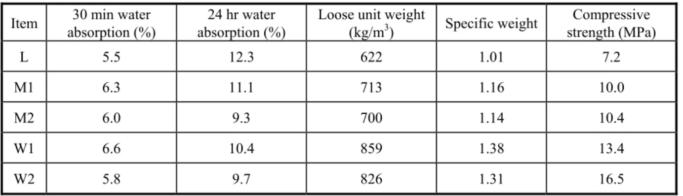
Table 2 Physical and mechanical properties of lightweight aggregates
Item 30 min water
absorption (%)
24 hr water absorption (%)
Loose unit weight
(kg/m3) Specific weight Compressive strength (MPa) L 5.5 12.3 622 1.01 7.2 M1 6.3 11.1 713 1.16 10.0 M2 6.0 9.3 700 1.14 10.4 W1 6.6 10.4 859 1.38 13.4 W2 5.8 9.7 826 1.31 16.5 Physical Properties
Many factors affect lightweight aggregates sintering results. To reduce the number of experimental variables, a fixed temperature was used in this research. The specific weight of the aggregates was controlled using only the rotation speed of the rotary kiln.
The preheating kiln rotation speed must be higher than the rotation speed of the firing kiln to manufacture aggregates with a smaller specific weight. The grains therefore stay in the preheating kiln for a shorter amount of time. The organic substances and sulfates can therefore be preserved. This means that a great quantity of gases will be discharged in the firing kiln. Low specific-weight aggregates are thereby produced.
The specific weight and water absorption of lightweight aggregates are shown in Table 2. The specific weight was between 1.01 and 1.38, corresponding to the target values. The 30 min water absorption is between 5% and 7%. The 24 hr saturated water absorption is between 9% and 13%. Compared with the data in the literature, the above test results were appropriate for high performance lightweight aggregates.
Mechanical Properties
The compressive strength of the produced lightweight aggregates is also shown in Table 2. These values were between 7 MPa and 17 MPa. The test results indicate that fine sediment lightweight aggregate can serve as structural aggregate.
CONCLUTIONS
The following conclusions are drawn from the results and discussion:
1. The chemical composition of the fine sediments gathered from the Shih-Men Reservoir satisfied to the
expansion demands for sintering artificial lightweight aggregates.
2. Sintering lightweight aggregates using a two-stage rotary kiln is possible. The main factor that controls the
aggregate specific weight is the kiln rotation speed.
3. The water absorption of lightweight aggregate decreased as the specific weight increased, and ranged from
9% to 13%. The compressive strength was between 7 MPa and 17 MPa. These values indicate that fine sediment lightweight aggregate can serve as structural aggregate.
REFERENCES
Bardhan-Roy, B. K. (1995), “Lightweight Aggregate Concrete in UK,” International Symposium on Structural Lightweight Aggregate Concrete, Norway.
Chen, H. J., Peng, H. S., Yen, T., and Wang S. Y. (2003), “Effects of Admixtures on the Production of Sintered Sintered Fine Sediments Lightweight Aggregate,” Journal of Engineering National Chung Hsing university, Vol. 14, No. 2, 107-144, (in Chinese).
Helgesen, K. H. (1995), “Lightweight Aggregate Concrete in Norway,” International Symposium on Structural Lightweight Aggregate Concrete, Norway.
Ikeda, S. (1995), “Development of Lightweight Aggregate Concrete in Japan,” International Symposium on Structural Lightweight Aggregate Concrete, Norway.
RESEARCH ON SEISMIC RETROFIT AND REHABILITATION OF REINFORCED CONCRETE SHEAR WALLS USING FRP MATERIALS
S. HIOTAKIS1, D.T. LAU2 and N. LONDONO3
ABSTRACT
This paper presents the results of an experimental study on the effectiveness of using externally bonded carbon fibre sheets as a retrofit and repair method for concrete shear walls. The experimental testing program, which has been carried out in two phases, is presented. The observed behaviours of the shear wall specimens are discussed. The test specimens include control walls, repaired walls, and strengthened walls. In the first phase, torsional behaviour of the walls is found to have significant influences on the wall performance. These observations from the first phase of the study have been used to improve the instrumentation and test set- up in the second phase. The study shows that the repair and retrofit method using carbon fibre sheets is effective in recovering the initial elastic stiffness of previously damaged wall specimens and in increasing the yield load and ultimate load carrying capacities of both repaired and retrofitted wall specimens.
Keywords: composite materials, concrete structures, construction technology, earthquakes, material and disaster prevention, repair and strengthening.
INTRODUCTION
In earthquake resistant design, shear walls are common lateral load resistance systems found in many reinforced concrete structures. Since the 1950’s, shear walls have been accepted as effective alternatives to moment resistant frames as the main earthquake resistance mechanism in seismic design of concrete structures.
Recently in Canada, the development of efficient methods for retrofitting existing deteriorated concrete structures is motivated by the need of extending the service of the large stock of aging concrete infrastructures, many of which have been designed decades ago using now obsolete and inadequate seismic design standards and practices. Earthquake experiences from around the world have shown that large earthquakes near urban centres can cause extensive structural damage. Therefore, in addition to retrofit methods, practical and effective repair techniques for earthquake damaged concrete structures are also needed. Many of the older shear wall buildings in Canada are at risk of suffering severe damage, or even collapse, during large earthquakes because of insufficient in- plane stiffness, flexural and shear strengths and/or ductility. The inadequacy in the lateral load resistance of these shear walls can often be attributed to the fact that seismic design provisions in older building codes did not properly account for the demands imposed on the shear wall structures by major earthquakes. As many of the existing buildings approach the end of their service life, the deterioration of the structural elements further exacerbates the problem.
Many different methods of seismic strengthening and repair of shear wall structures have been developed and tested in the last thirty years. These techniques include the strengthening of existing shear walls by the application of shotcrete or ferrocement, filling in openings with reinforced concrete and masonry infills, and the addition of new shear walls and steel bracing elements (FEMA, 1992). Research studies have shown that the method of concrete jacketing of a damaged shear wall can restore the gravity load carrying capacity of the wall, but is not as effective when the objective is to restore the lateral stiffness of the structure. For strengthening, an upgrade method is the addition of steel bracings to the shear walls. Although this method is effective in recovering and enhancing the lateral stiffness of damaged and undamaged shear walls, respectively, it is
1
Graduate student, Dept of Civil and Environmental Engineering, Carleton University, Ottawa, Canada, email: shiotakis@ccs.carleton.ca.
2
Professor, Dept of Civil and Environmental Engineering, Carleton University, Ottawa, Canada, email: dtl@ccs.carleton.ca.
3
Ph.D. candidate, Dept of Civil and Environmental Engineering, Carleton University, Ottawa, Canada, email:nlondono@ccs.carleton.ca.
Paper presented at the NSC-NRC Taiwan-Canada Workshop on Construction Technologies National Center for Research on Earthquake Engineering, Taipei, 25 -30 April 2004
architecturally unappealing since it changes the exterior and/or interior layout of the structure, resulting in a significant reduction of the building’s usable space. It may also add significant weight to the structure and thus alter the magnitude and distribution of the seismic loads. Also, the existing techniques are genera lly very labour intensive and disruptive to the operation of the facilities during the construction period, which often means the complete shutdown of the facilities and relocation of the occupants.
Recently, applications of composite materials have been introduced as effective alternatives to conventional techniques for retrofit and repair of reinforced concrete structures. Presently, these advanced composite materials are more often used in the retrofit and repair of columns and beams (Saadatmanesh et al., 1994). Information on the use of advanced composite materials for shear wall repair and retrofit are lacking. The advantages of composite materials compared to traditional strengthening materials are the high strength to weight ratio, excellent corrosion resistance, and ease of handling (Meier et al., 1992).
The research reported herein is a continuing experimental research program that is being carried out at Carleton University on the feasibility and effectiveness of the use of composite materials for strengthening and repair of reinforced concrete shear walls. The composite materials used in this study are unidirectional carbon fibre reinforcement polymer sheets, externally bonded on the surface of the wall with an epoxy resin matrix. The experimental testing programs have been carried out in two phases. Detailed description of the experimental set up for both phases are given below. The observations and results from the first phase are used to improve the test set- up and test procedures in the seco nd phase. Comparisons are made of the test results from the two phases.
CARBON FIBRE REINFORCEMENT POLYMER SHEETS
The carbon fibre reinforcement polymer (CFRP) sheets used as reinforcement in the experimental study are high strength unidirectional continuous carbon fibre tow sheets. The CFRP sheets are bonded externally on the face of the shear wall by an epoxy matrix. In the first phase of the study, carbon fibre sheets have an elastic tensile modulus of 230 GPA, a tensile strength of 3,480 MPa, and an ultimate strain of 1.5%. The carbon fibre material behaves linearly elastically until failure. In phase two, similar carbon fibre sheets are used except that the tensile strength is 4,800 MPa, and the ultimate strain is 1.7%.
In the repair and retrofit method using CFRP sheets, the flexural strength of a shear wall is increased by applying the CFRP sheets with the fibres oriented in the vertical direction. Essentially, the added CFRP sheets contribute to the flexural strength of the wall in similar mechanisms as the vertical steel reinforcements. For enhancement to the shear strength of a shear wall, the CFRP sheets are bonded externally to the wall with the fibres oriented in the horizontal direction. In order for the vertical CFRP sheets to be effective in contributing to the flexural strengthening of the wall, the CFRP sheets are anchored at the wall base through a load transfer mechanism to transfer the load carried by the CFRP sheets to the support of the specimen. The anchor system used in the first phase of the experimental study consists of a structural steel angle bolted to the support of the specimen. An improved anchor system is used in the second phase study.
EXPERIMENTAL SETUP
The specimens tested during phase one of the experimental study are reinforced concrete shear walls constructed with 40 MPa concrete and 400 MPa yield strength steel reinforcement. The wall specimens are 1500mm wide, 100mm thick, and the distance between the construction joint of the wall at the footing to the point of load application is 2000mm. The flexural reinforcement consists of six pairs of 10M reinforcing bars spaced at 280mm, providing a reinforcement ratio of 0.8%. The shear steel reinforcement consists of five pairs of 10M re-bars spaced at 400mm for a reinforcement ratio of 0.5%. Details of the steel reinforcement of the specimen are shown in Figure 1. The wall specimens are tested to failure in the in- plane direction subjected to a predetermined increasing quasi-static cyclic load pattern. The load is transferred to the wall through a horizontal cap beam by a hydraulic actuator supported by a reaction frame. The four shear wall specimens of the first phase study include a control wall, a repair wall, and two strengthened walls. The testing of the control wall provides base reference information for the investigation of the effectiveness of the strengthening and repair method using CFRP sheets. The control wall was loaded beyond the maximum resistance of the wall. The test stopped when approximately a 10% drop of its resistance from the peak was observed. The repaired wall test results were obtained from testing of the damaged control wall after repair by applying CFRP sheets. The first strengthened wall (wall No.1) was strengthened with one vertical ply of carbon fibre sheets. The second strengthened wall (wall No.2) was strengthened with two vertical plies of carbon fibres and one in the horizontal direction. The
carbon fibre sheets were applied on the wall surface with epoxy. No load was applied to the strengthened specimens prior to testing. After a 14-day curing period of the epoxy, the specimens were tested to failure.
EXPERIMENTAL TEST RESULTS Observations from Phase 1 Study
Control Wall
The behaviour of the control wall as described by the load versus top horizontal displacement curve is presented in Figure 3. The first tensile cracks in the concrete were observed at an average measured load of +/-55 kN. The cracks were horizontal and formed at the edges of the wall near the base. Yield ing of the extreme tensile steel reinforcement was observed at an average measured load of 122 kN and an average displacement of 3.7 mm. The wall reached its maximum resistance at 178 kN. A final load cycle was then applied to a displacement of 18 mm, resulting in a drop of approximately 10% in the peak resistance. At that point, the test was stopped as this specimen had to be maintained at a repairable state for use as a repaired wall specimen.
Repaired Wall
The damaged control wall was repaired by ap plying one layer of vertical carbon fibre to each face of the wall and was subsequently tested again to failure. The behaviour of this specimen as described by the load versus top horizontal displacement curve is presented in Figure 4. Yielding of the extreme tensile reinforcement was measured at an average load of 158 kN, corresponding to an average displacement of 5.4 mm. The repair by the CFRP sheets recovered 90% of the original elastic stiffness and increased the yield load by 29%. The average maximum resistance of the repaired wall reached a load of 320.7 kN. The reinforcement method resulted in an increase of the ultimate load-carrying capacity of the repaired wall compared to the control wall by 80%. The failure mode was observed to be ductile flexural failure.
Strengthened Wall No. 1
The first retrofit specimen was strengthened by the application of one vertical layer of carbon sheets on each side of the wall. The behaviour of the wall as described by the load versus top horizontal displacement curve is presented in Figure 5. The first flexural cracks on the tensile side of the concrete specimen were observed at an average measured load of 100 kN. This corresponded to 62% of the yield load, indicating that the application of the carbon fibre sheets resulted in an 82% increase in the cracking strength of the wall. The cracks were again horizontal, appearing near the wall base. From the load-deflection curve, it was determined that yielding of the extreme layer of flexural steel reinforcement (vertical) occurred at an average measured load of 153 kN, with an average displacement of 1.6 mm. Compared to the control wall, the application of the fibre reinforced polymer sheets to strengthened wall No. 1 resulted in a 25% increase in its yield strength. Furthermore, the carbon fibre sheets contributed to an increase in the secant stiffness of the wall at yield by 190%.
The average maximum resistance of the strengthened wall reached a load of 258 kN. The retrofit resulted in an increase of the ultimate load-carrying capacity of the strengthened wall compared to the control wall by 46%. The failure mode was observed to be ductile flexural failure. The failure of the strengthened wall No.1 occurred as compression failure of the toe and simultaneous fracturing of one of the extreme flexural reinforcing bars. During the test, the expansion anchor bolts of the anchoring system occurred slipped. This resulted in the reduction of the ultimate load carrying capacity of the wall specimen, which when co mpared to the repaired wall, exhibited a 20% decrease in the load carrying capacity.
Strengthened Wall No. 2
The second retrofit specimen was strengthened by the application of two vertical layers of carbon sheets and one horizontal layer on each side of the wall. The behaviour of the wall as described by the load versus top horizontal displacement curve is presented in Figure 6. The first flexural cracks on the tensile side of the concrete specimen were observed at an average measured load of 102 kN. This corresponded to approximately 50% of the yield load. Comparing the results of the two strengthened walls, it was observed that the effect of the additional carbon fibre sheets (one vertical and one horizontal) had little significance on the cracking strength of the wall. The cracking pattern observed was similar to the pattern observed for strengthened wall No. 1. Yielding was observed at an average measured load of +/-201 kN, corresponding to an average displacement of 2.4 mm. As compared to the control wall, the results obtained corresponded to a 39% increase in the yield strength and a 54% increase in the stiffness.
upgrade resulted in an increase of the ultimate load-carrying capacity of the strengthened wall compared to the control wall by 132%. The failure mode was ductile up to the point where rupture of the carbon fibre sheets occurred, at which time there was an abrupt drop in the load carrying capacity of the wall by approximately 60%, compared to an average of 27% loss when rupture of the vertical re-bars occurred. The failure was attributed to flexural failure.
Observations from Phase 2 Study
During the first phase of the experiment s, it was observed that the specimens exhibited significant out-of-plane torsional deformations. This was due to the lack of sufficient lateral restraint of the shear wall specimens. During testing, any minor eccentricity originally attributable to the construction of the specimen led to torsional out-of-plane behaviour of the specimen. Observations from the tests conducted in Phase 1 of the study indicate that the torsional effect has a significant impact on the behaviour and performance of the shear walls. To alleviate this problem, a new test set- up and instrumentation scheme were designed for the new series of tests in phase 2 of the study. The new test set-up included the design of a lateral restraint mechanism to prevent out-of-plane deformations of the wall during the load tests.
Another modification implemented in the Phase 2 tests was that strain gauges on the steel rebars were relocated and better protected from damage during the pouring of the concrete. Rosette strain gauges were also installed on the surface of the walls (Figure 2) to measure the shear strain of the wall specimens. The locations of displacement measurements by potentiometers are shown in Figure 2. Two diagonal potentiometers were used to measure the average shear deformations of the wall panel. The dimensions of the specimens tested in Phase 2 of the study were the same as those in Phase 1. The test results from this second series of tests are presented as follows.
Control Wall
The behaviour of the control wall as described by the load versus top horizontal displacement curve is presented in Figure 7. The first tensile cracks in the concrete were observed at an average measure load of +/-82.5 kN. The cracks were horizontal and formed at the edges of the wall near the base similar to the behaviour observed in Phase 1 of the research program. Yielding of the extreme tensile steel reinforcement was observed at an average measured load of 140 kN and an average displacement of 4.67 mm. The wall reached its maximum resistance at 194 kN. The test was continued until a drop of approximately 20% of the maximum resistance was reached and then stopped for repair and testing again as a repaired wall.
Repaired Wall
The control wall tested above was repaired by first repairing the damaged concrete with epoxy grout. Following, one layer of vertical carbon fibre sheet was applied to each face of the wall. The repaired specimen was subsequently re- tested to failure. The load versus top horizontal displacement curve of the repaired wall specimen is presented in Figure 8. Yielding of the extreme tensile reinforcement was measured at an average load of 168 kN, corresponding to an average displacement of 3.25 mm. The CFRP repair recovered 88% of the original elastic stiffness and increased the yield load by 22%. The average maximum resistance of the repaired wall reached a load of 280 kN. The repair by FRP sheets resulted in an increase of the load-carrying capacity compared to that of the control wall by 44%. The failure mode was ductile flexural failure. Figure 8 shows that the repaired wall specimen attained a displacement ductility of about 12 while maintaining approximately 35% of the peak lateral load resistance at ultimate failure. It is also noted that the energy dissipation capacity of the wall was greatly depleted towards the end of the loading sequence just before failure.
Strengthened Wall No. 1
The first strengthened wall was upgraded by the application of one vertical layer of carbon sheet on each side of the wall. The load versus top horizontal displacement curve of this wall specimen is presented in Figure 9. The first flexural cracks on the tensile side of the concrete specimen were observed at an average measured load of 120 kN. This corresponded to 72% of the yield load, slightly lower than the result obtained in Phase 1 of the research program, but still represented a 45% increase in the cracking strength of the wall. Similar crack patterns as in Phase 1 of the study were observed. The average measured yield load was determined to be 166 kN at the yield displacement of 3.9 mm. Compared to the control wall, the application of the fibre reinforced polymer sheets resulted in a 19% increase in its yield strength, which is slightly less than the increase observed in Phase 1 of the study. The increase in the secant stiffness of the wall at yield as a result of the CFRP strengthening was 213%.


![Figure 1. Reinforcement Details of Reinforced Concrete Shear Wall Specimens. Dimensions in [m]](https://thumb-eu.123doks.com/thumbv2/123doknet/14190713.477971/28.918.181.691.282.770/figure-reinforcement-details-reinforced-concrete-shear-specimens-dimensions.webp)