Development of a Manufacturing Strategy for
a Low Investment, Bent Tube Space Frame
Vehicle in North America
ByGregory T. Webb
B.S. Mechanical Engineering, The Ohio State University 1998 Submitted to the Sloan School of Management and the Department of Mechanical Engineering in partial fulfillment of the
Requirements for the degrees of Master of Business Administration
And
Master of Science in Mechanical Engineering
In conjunction with the Leaders for Manufacturing program at the MASSACHUSETTS INSTITUTE Massachusetts Institute of Technology OF TECHNOLOGY
June 2003
AUG 0 4 2003
© Massachusetts Institute of Technology, 2003.
All rights reserved. LIBRARIES
Signature of Author
/
4/
Sloan School of ManagementDepartment of Mechanical Engineering May 9, 2003
Certified by
Thomas Roemer Assistant Professor of Management Science Thesis Supervisor
Certified by
Dr. Daniel Whitney Senior Research Scientist, MIT Ctr for Tech, Policy and Industrial Development Thesis Supervisor
Accepted by
Margaret Andrews Executive Director of Master's Program
Slow Management
Accepted by __ _ Ain___
Aim Sonin
Chairman, Departmental Committee for Graduate Students Department of Mechanical Engineering
Development of a Manufacturing Strategy for a Low Investment, Bent Tube Space Frame
Architecture Vehicle in North America By
Gregory Webb
Submitted to the Sloan School of Management and the Department of Mechanical Engineering on May 9, 2003 in Partial Fulfillment of the Requirements
for the Degrees of Master of Business Administration and Master of Science in Mechanical Engineering
ABSTRACT
The North American automotive market has become increasingly segmented in recent years with an abundance of "niche" vehicles and increased competition from foreign transplant companies. Because of this increased segmentation, typical production volumes per model have decreased. The number of models that sell in the three or four hundred thousand units per year range
continues to decrease. These reduced volumes require that automotive manufacturers find a way to reduce the required investment to bring a new product to market and mass produce it.
This thesis develops a manufacturing strategy for producing a low volume vehicle in North America using a bent tube space frame architecture. The body panel processes are chosen from a variety of materials and processes based on panel properties, investment and part costs. The framing operation and body panels are tied together in a process sequence. Overall investment figures are calculated for the plant and manufacturing system.
This thesis determines that a pure bent tube space frame is not the most effective way to achieve low investment manufacturing in North America, although it may be profitable utilizing the Mexico labor market. This type of architecture is more appropriate as part of a global strategy involving developing markets. This type of space frame architecture could be used to enable increased manufacturing flexibility and could be more appropriate for North American use if combined with other technologies such as hydroforming.
Thesis Advisor: Dr. Daniel E. Whitney, MIT School of Engineering Prof. Thomas Roemer, Sloan School of Management
Acknowledgements
First, I would like to thank the Leaders for Manufacturing (LFM) program at MIT for the incredible learning opportunity that they have provided me with. The seven-month internship at General Motors was just one of the many components of what has been a life-changing
experience. The LFM network of faculty, staff, students and alums has provided me with a very supportive network of teachers, colleagues and friends. In particular, I expect that the bonds I have formed over the last two years with my classmates and friends will continue to grow for a long-time to come. I have learned so much from their rich, diverse backgrounds and look forward to sharing more experiences with them in the future.
I would also like to thank the General Motors Corporation for their continued support of the
LFM program. Their generous sponsorship of my internship project allowed me to begin applying some of what I have learned at MIT and continue the learning in a real business environment.
I could not have completed this project without the support of so many people at General
Motors. My supervisors, Chris Williams and BJ Lee, helped guide me through the entire process and ensured that I had access to all of the necessary resources. I would also like to thank Cara W., Kathleen D., Len B., Phil D., Dan C., Ray K., Mike R., Bob A., Hamid K., Theresa L., Joe
H., my classmate and fellow intern Kristin and the many others that provided their support and
expertise every time I needed it. There were so many within GM that had a part in making this project a success that I cannot possibly list them all here. I hope everyone realizes how much I
appreciated his or her support.
I would also like to thank my MIT thesis advisors, Professor Thomas Roemer and Dr. Daniel
Whitney. Their support and expert guidance helped me get through both the internship project and the writing of this thesis. Their experience helped provide me with direction throughout the entire process.
The author would like to note that some data for this thesis has been modified or disguised to protect confidentiality concerns of the host company. Those edits have
TABLE OF CONTENTS
1 INTR O D U CTIO N ... 9
1.1 Industry Background ... 9
1.2 Com pany Background ... 10
1.3 Organizational Structure ... 14
1.4 Project D escription... 14
1.5 Thesis Overview ... 15
2 VEH ICLE A R CH ITEC TURE ... 17
2.1 Traditional Stam ped Architecture... 17
2.1.1 BOF...17
2.1.2 BFI...18
2.2 Space Fram e Architecture... 19
2.3 Architecture Com parison ... 21
2.4 Chapter Sum m ary ... 25
3 M A N U FA CTU RIN G PR O CESS ... 27
3.1 A ssem bly Plant Process Flow ... 27
3.2 Fram e Shop Process Details ... 29
3.3 Bond Shop Process Details ... 34
3.4 General A ssem bly Process Details... 37
3.5 Chapter Sum m ary ... 39
4 BO DY PA N EL M A N U FA CTURING ... 41
4.1 Com posite Processes Considered ... 41
4.2 Open M old Fiberglass... 43
4.3 V EC@ Technology ... 48
4.4 Com posite Technologies Com bination... 51
4.6 Cost Com parison and Conclusions ... 56
4.7 C hapter Sum m ary ... 59
5 LOW INVESTMENT STRATEGY CONCLUSIONS...61
5.1 Conclusions on Bent Tube Space Frame Construction in North America ... 61
5.2 Global Strategies With Bent Tube Space Frame Construction...64
5.3 D eciding on a V ehicle Architecture... 65
5.4 Global Low Investment Strategy Conclusions ... 67
5.5 Low Volume / Low Investment Enablers and Hurdles...69
5.6 Results of Project and Action Taken Within General Motors ... 72
5.7 O verall C onclusions... 73
R EFER EN C ES...75
A PPEN D IC E S...76
Appendix 1 2001 North American Production of GM Vehicle Models...76
Appendix 2 Body Panel Parts Included in Analysis for this Project ... 77
LIST OF FIGURES
1-1: Volume Distribution of Vehicle Models in 2001 GM Production...11
1-2: Volume Distribution of Vehicle Platforms in 2001 GM Production ... 12
2-1: B ody-on-Fram e A rchitecture ... 18
2-2: Body-Frame-Integral Architecture . ... 19
2-3: Space Fram e A rchitecture ... 20
2-4: V ehicle A rchitecture V arieties ... 22
3-1: A ssem bly Plant Process Flow ... 27
3-2: Frame Shop Process Sequence ... 30
3-3: B ond Shop Process Sequence... 36
4-1: Body Panel Tooling Investment Comparison... 42
4-2: Open Mold Automation Analysis... 47
4-3: Body Panel Technology Cost Comparison... 57
5-1: Total Plant Investment and Labor Costs ... 62
CHAPTER 1 - INTRODUCTION
1.1 Industry Background
The North American automotive market has become increasingly segmented in recent years with an abundance of "niche" vehicles and increased competition from foreign transplant companies. The lines that used to separate distinct product segments have become blurred by the presence of more and more hybrid, or crossover, vehicles. Because of this increased segmentation, typical production volumes per model have decreased. The number of models that sell in the three or four hundred thousand units per year range continues to decrease. These reduced volumes require that automotive manufacturers find a way to reduce the required investment to bring a new product to market and mass produce it.
In the 1980's there were only a handful of sport utility vehicles on the market and they were basically one of two different sizes. Compare that to today, where there are over sixty-five sport utility models available as 2003 models in the United State. For almost any size of SUV a consumer could want, they will find themselves with at least a few different options. In that same amount of time, the selections of cars and trucks have also increased. The total volume of vehicles sold in the US has increased only slightly. In total, there are more than 275 car, truck, van, SUV, and crossover models for sale in 2003. With total sales of 16.8 million vehicles in the
US in 2002, that's an average of just over 60,000 units per model. The number of models on the
market has increased by 10% over the last decade and market forecaster Global Insight predicts it will increase by another 6% within the next four years.
1.2 Company Background
General Motors (GM) is the world's largest automotive manufacturer and currently has a worldwide market share of over 15% and a US market share of over 28%. GM vehicles in the
US are sold under the brand names of Buick, Cadillac, Chevrolet, GMC, Hummer, Oldsmobile,
Pontiac, Saab and Saturn and there are over 60 GM models available as 2003 models. With 2002 US sales of approximately 4.7 million vehicles, GM's average production is approximately
78,000 units per model.
Figure 1-1 below shows the range of production volumes for GM models that were produced in 2001. The chart shows that there were 26 GM models produced in volumes of less than 50,000 units in 2001. Almost half of the total models were produced in what most people would
consider low volume for automotive production. There were 11 models produced in volumes of
50,000-100,000, 16 models produced in volumes of 100,000-200,000 and 4 models produced in
volumes greater than 200,000. A complete list of GM models manufactured in North America in 2001 and their production volumes can be found in Appendix 1. The largest volume product, by far, was the Chevrolet Silverado with 2001 production of more than 700,000 units. Its GMC sibling, the Sierra, had 2001 production of more than 200,000 units using many of the same parts. It's important to note that a few of the models produced in 2001 were not produced for the full year, since they were old models being phased out or new models that began production mid-year.
Figure 2-1: Volume Distribution of Vehicle Models in 2001 GM Production
30
-25 .
0-50k 50k-100k 100k-200k 200k+
Total 2001 Production per Model
To deal with these decreasing production volumes, GM in recent years has increased their emphasis on global vehicle platforms and parts reuse. A platform approach to vehicle manufacturing uses many of the same underbody, chassis and structural components to build multiple vehicles. For example, underneath their exterior, the Chevrolet Camaro and Pontiac Firebird have a lot of parts commonality between them. This makes it much easier to
manufacture them on the same assembly line and reduces the number of tools and total tooling investment required. Only 27,108 Camaros were produced in 2001, along with 20,281 Firebirds. However, that means there were 47,389 cars produced using many of the same tools and parts. There are many other examples of parts sharing strategies within the GM portfolio and in recent years it has taken on more of a global emphasis. GM is focused on leveraging its global size by
U) *0 0 E) Z. 20 -15 10 5 0
developing vehicle platforms that can be used not only for its US models, but also for brands and models that it sells in other parts of the world. If several distinct models can be designed from
one common platform, some of the tooling investment costs and development costs can be spread across much larger production volumes. Figure 1-2 shows the range of production volumes for GM platforms that were manufactured in 2001.
Figure 3-2: Volume Distribution of Vehicle Platforms in 2001 GM Production
9 ,1 8 7 -(0 0 '4-('3 0 a) -0 E I 6 5 4 3 2 1 0 4 0-50k 50k-100k 100k-200k 200k+
Total 2001 Production per Platform
This platform strategy can also enable more plant flexibility and allow more models to be manufactured on the same production line with reduced investment. Vehicles built off of the same platform are typically built using the same processes, have similar sizes and share some of the same body shop tooling. The main differences between the models come from the body
panels that provide its exterior styling and components assembled to a completed body to
provide the desired performance and functionality. Effective use of global vehicle platforms can reduce GM's manufacturing plant and tooling investments, especially in the body shop area.
As can be seen in the figure, the platform volumes paint a very different picture than the model volumes. There were seven vehicle platforms produced in volumes under 50,000 units and three of those were because they were new platforms, just beginning production during 2001, or old platforms, being phased out mid-year in 2001. At the other end of the spectrum, there were eight platforms that were produced in volumes greater than 200,000 units. The largest volume
platform by a large margin was the CK platform with over 1.5 million vehicles produced in 2001. GM had nine full-size pickup and SUV models built off of the CK platform in 2001. However, there is limited commonality across the entire CK family. Although they are all considered the same platform, they are built on several different frames to provide a variety of lengths, wheelbases, and load ratings. There are also a variety of drive trains, suspensions and other components. There are limits to how much common tooling can be used across a vehicle platform while still allowing for each model to be unique and targeted at a different market.
GM North America's (GMNA) headquarters are in Detroit, Michigan. A majority of the vehicle
design and development work for GMNA vehicles is performed at the Technical Center campus in Warren, Michigan, with several thousand GM employees also located at a campus in Pontiac, Michigan. GM's North American vehicle production takes place at over 30 different plants. While most are located in the United States, there are a few in Canada and a few in Mexico.
1.3 Organizational Structure
This project was completed while working at General Motor's Technical Center in Warren, Michigan. The author worked in the Advanced Vehicle Development Center (AVDC) in the Manufacturing Engineering organization, which reports up through the Vice President of Vehicle Operations. This organization is responsible for the manufacturing engineering work for
products that are in the very early stages of development. They work very closely with
individual functional areas to gain a full understanding of how a vehicle will be manufactured if it is developed. They work with other experts as the team develops manufacturing process details, plant layouts, investment estimates, headcount estimates, etc.
The author was not a member of an existing team, but did work with members from a variety of other teams. The project supervisor was a Manufacturing Integration Manager in the AVDC Manufacturing Engineering department.
1.4 Project Description
The goal of this project is to develop a low investment manufacturing strategy that will help GM adapt to the decreasing model volumes in the North American automotive market. Everyone has their own idea of what defines "low volume" manufacturing, but for this thesis low volume automobile manufacturing is considered to be 50,000 units per year or less. The manufacturing strategy developed will be geared towards building a family sedan with annual volumes of fewer than 50,000 units, which is not much less than GM's current average production of 78,000 units per model.1
"Sedan" is a general term for a car that has a front and rear seat as well as a permanent roof. It typically has 4 doors and seating capacity for 4 or 5 persons.
The manufacturing strategy is based on North American production using a bent tube space frame architecture, which is a different structure than most mass-produced vehicles today. This project looks at how that bent tube space frame should be manufactured, how it compares in cost to more traditional architectures, as well as what types of advantages and disadvantages it
presents.
Along with the frame construction, this project also looks at the body panel alternatives that could be used to complete assembly of the vehicle. It focuses on a few of the more non-traditional composite alternatives to explore how they might be used to enable this type of low volume vehicle program.
The manufacturing strategy is intended to be for production in North America. For that reason, the project looks at production in the United States as well as production in Mexico. The two countries have very different labor markets, so this project will take a look at how those labor differences affect the manufacturing strategy. As another point of comparison and in order to consider a global strategy, it will also look at implications of executing this type of program in a Far East country where labor rates are significantly lower than Mexico.
1.5 Thesis Overview
Chapter 1 provides some background for this thesis project. It provides background on the
industry and company and explains part of the motivation for this project. It then explains the project purpose and goals.
Chapter 2 discusses vehicle architectures. It will describe the three basic categories of vehicle
architectures and will compare and contrast them. It explains the motivation behind choosing a bent tube space frame architecture.
Chapter 3 provides a manufacturing process overview for constructing a bent tube space frame
vehicle. It shows the overall manufacturing plant flow and provides some detail for the activities within each area.
Chapter 4 describes the materials and manufacturing processes considered for constructing the
body panels. It provides some technical background for each process and discusses some of the advantages and disadvantages. The chapter ends with an overview of the financial analysis for each material strategy and selects the optimal strategy.
Chapter 5 details the conclusions drawn from this project. It details the conclusions drawn about the viability of bent tube space frame vehicles in the US and Mexico. It also touches on how things might be different in developing countries of the Far East and what this all means for a global low investment strategy for GM.
CHAPTER 2 - VEHICLE ARCHITECTURE
2.1 Traditional Stamped Architecture
Three primary architecture types are used to build passenger vehicles. The term architecture in this setting is used to describe how the chassis is designed to provide structure. What type of basic topology is used to provide the vehicle with its shape, strength and closure? Most passenger vehicles on the market today are designed using either a body-on-frame (BOF) or body-frame-integral (BFI) architecture. The third architecture type, which in its purest form is typically not used for mass production vehicles, is a space frame. This space frame construction is the one explored for this thesis. However, for comparison purposes, a brief description of BOF and BFI construction will also be provided.
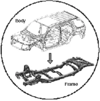
2.1.1 Body-on-Frame (BOF)
BOF architectures were originally used for all cars and are used today for most trucks, full-size vans and large sport utility vehicles. The underlying steel frame provides a large portion of the strength for BOF vehicles. A BOF frame typically consists of two frame rails, running the length of the vehicle, connected at multiple points with frame members running across the width of the vehicle. Figure 2-1 below shows a typical BOF frame as well as the body that might be mated to it. The engine, transmission, suspension, steering, bumpers, etc. are attached directly to this frame. The body of the vehicle is traditionally designed using stamped metal parts that are spot welded together. In increasingly more cases, alternative materials such as composites and aluminum are being used for some or all of these body panels.
In a BOF vehicle, the body itself does not have to be designed to provide all of the strength and rigidity because it can rely on the heavy-duty frame to provide most of the torsional rigidity as well as the strength for front end or rear end collisions. This structural frame can then be used for other models as well, spreading the investment costs across a larger volume of vehicles. Each model is made unique by having a different body mounted onto the frame.
Figure 2-1: Body-on-Frame Architecture
2.1.2 Body-Frame-Integral (BFI)
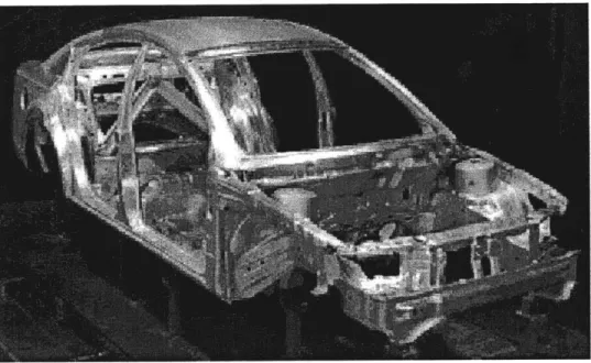
BFI architectures are used for most passenger cars, mini-vans and small sport utility vehicles on the market today. Many people also refer to the BFI structure as a unibody (unitized-body) vehicle. This BFI structure differs from the BOF structure in that it does not have a separate
frame underneath the body. Figure 2-2 below shows a BFI constructed vehicle. The stamped panels are designed to provide all of the necessary strength and rigidity for the completed vehicle. The engine, transmission, suspension, steering, etc. is bolted directly to stamped body
panels. While steel has been by far the most widely used body panel material, the use of composites for selected panels as well as the use of aluminum has begun to gain some
momentum. Jaguar's 2004 XJ is an example of a car that has been built with an all aluminum body, although the higher cost and some processing issues still make it prohibitive for more
frequent use on all types of car models.
Figure 2-2: Body-Frame-Integral Architecture
2.2 Space Frame Architecture
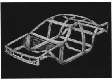
A tubular space frame construction can be thought of as being similar to a birdcage, or similar to
the way that a house is built. In house construction, the strength of the building is provided by a series of two-by-fours and other boards, fastened together to form a cage-like structure. Panels such as insulation and drywall are then attached to this wooden frame to provide the house with closure and separate the interior from the exterior. In a space frame vehicle, the strength and rigidity of the vehicle is provided by a set of structural tubes, which are fastened together by
welding or mechanical fasteners to form a similar cage-like structure. The frame members are designed and connected so that they are loaded primarily in tension and compression. The engine, transmission, suspension, steering, etc. are mounted directly to structural members of the space frame. Body panels can then be mounted onto this space frame structure to provide it with closure to block out the weather, wind, debris, noise, etc. Figure 2-4 below shows a typical space frame structure.
Figure 2-3: Space Frame Architecture
Tubular space frame construction is used in some specialty and super low volume products, such as race cars, monster trucks and Lamborghini's, but is typically not used for mass produced vehicles.
All of the body panels for the car are mounted to the finished space frame pictured above. There
also interior body panels that close out the interior of the car from the frame. Depending on how the frame is designed and how the body panels are manufactured, a completed car may require 25 to 40 panel part numbers. For analysis purposes in this thesis, it is assumed that the car being manufactured requires 30 panel part numbers. Appendix 1 provides a list of the parts that are included.
2.3 Architecture Comparison
While most automotive engineers would agree that there are three basic types of vehicle
architecture, classifying individual models into one of the three categories is not always a clear-cut decision. Many vehicle designs blend characteristics from more than one category. Figure 2-4 below depicts the range of architectures and shows where some current models would fit on the continuum.
As indicated in the figure, there are two main variations on the BFI design that bring it closer to the BOF architectures. One of the variants is a BFI type body structure with an engine cradle. The other variant is a BFI type body structure with both an engine cradle and a rear suspension cradle.
Two primary frame rails that extend from the front end of the body form an engine cradle. The front bumper, engine, steering, and front suspension are then mounted to this engine cradle. The front end is built similar to a BOF vehicle, while the rest of the car is built like a typical BFI car. The Buick Park Avenue and Cadillac Seville both use this type of structure.
The rear suspension cradle is the same basic concept as the engine cradle. It consists of two primary frame rails extending from the rear of a BFI type body. The rear bumper, suspension and brake components are mounted to this rear suspension cradle. Cars built with a rear
suspension cradle also typically are designed with an engine cradle. The front and rear ends are both built similar to a BOF vehicle, while the rest of the car is built like a typical BFI car. This type of body structure is used for the Buick Rendezvous.
Figure 2-4: Vehicle Architecture Varieties
BFI
Engine Chevy -Cradle Cavalier Cadillac Park Ave.Chevy Corvette Engine Cradle +
Rear Suspension
Cradle Buick
Rendezvous Chevy Silverado
SF
B F
lureBentChevy
Trailblazer
Tube Space
Of the vehicles shown in Figure 2-4, the Chevrolet Corvette is the closest thing to a space frame
architecture. In some areas it does have a cage-like structure. However, it also has a touch of both BFI and BOF architectures in its design. It relies on stamped parts to provide strength and structure in some areas, similar to BFI. It also has two main frame rails that run the length of the car and provide a lot of its strength and rigidity, similar to BOF. The Corvette's hydroformed frame rails differ from a true BOF in that the body does not sit on top of them. The rails are integrated into the body design and run through the structure in some areas.
One of the main benefits of space frame construction is that it requires a lower up front
investment. A significant portion of body shop investment for BOF and BFI vehicles is for the body panel stamping dies. Since a space frame car requires a greatly reduced number of
stampings, this stamping die investment is also greatly reduced. How much the stamping die investment is reduced depends greatly on what type of body panels are used. This thesis
explores a few of the body panel alternatives and the resulting investment reduction in later sections.
Another potential benefit of space frame construction could be in product design flexibility. The underlying frame structure provides all of the strength and rigidity for normal vehicle
performance as well as crash worthiness. The main purpose of the body panels, both interior and exterior, is to provide closure. The shape and contours of the body panels can also be used to define the styling of the vehicle. Due to this fact, some styling variety can be achieved more easily by hanging panels with different contours on the same underlying frame structure. This
could make the development of these alternate styles a much easier and cheaper process. In stamped BFI vehicle, the body panels provide the closure and styling, but they also contribute significantly to the structure of the vehicle. Therefore, a change to the styling of the body panels requires significant testing to ensure the resulting structure still meets all of the performance requirements. However, if a space frame construction is used and the styling changes are done
solely through different contours on the non-structural body panels, it could require a reduced amount of performance testing and savings in the millions or tens of millions of dollars range. In Chapter 3, this thesis will explore some of the process details for the space frame construction. From these process details, a couple of basic conclusions can be drawn about the manufacturing
flexibility compared to stamped BFI architectures.
A couple of the drawbacks for bent tube space frame construction are that it has a higher part
count and requires more labor. Because of the higher part count, a huge amount of welding has to be done to join components together. In fact, the space frame for a small family sedan could require as much as 50 meters of welding. Welding these frame components together also requires a large number of body shop fixtures to locate and hold the pieces in place.
Hydroforming is a process that could be used to create space frame structures that are not quite as labor intensive and have a much lower part count.2 With hydroforming, frame components can be designed to have more complex geometries, so that fewer parts are needed. They can also be designed to include locating features so that fewer fixtures are needed in the body shop. 2 Hydroforming is a process of shaping steel tubes through the application of water at extremely high pressure.
It replaces traditional stamping processes, preserving more of the steel's strength and stiffness as it goes through the forming process. It is performed at low temperatures to retain optimal material properties, resulting in high strength and stiffhess, relatively low weight, precise quality and reduced material usage.
However, for this thesis, hydroforming was not considered as an option. The goal of this project was defined as developing a manufacturing strategy for a pure bent tube space frame vehicle. Hydroforming does require significant tooling investment, so maintaining a pure bent tube construction is an attempt to minimize the overall manufacturing investment.
2.4 Chapter Summary
This chapter has defined and described the three main types of architectures that can be used in vehicle manufacturing: BFI, BOF and space frame. It described when and where each of the architecture types is typically used and then compared the advantages and disadvantages of using a space frame.
The following chapter will explore the manufacturing process for a bent tube space frame vehicle. It describes the overall assembly plant process and provides a more detailed process sequence description for those processes that may be unique to using a bent tube space frame.
CHAPTER 3 - MANUFACTURING PROCESS
3.1 Assembly Plant Process Flow
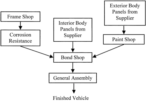
The overall assembly plant process flow for building a bent tube space frame vehicle is similar to traditional plants, but there are a couple of significant differences. Figure 3-1 below shows this
overall process flow.
Figure 3-1: Assembly Plant Process Flow
Exteri Panel
Frame Shop Sup
Interior Body
Panels fromCorrosion Supplier Paint
Resistance Paint
Bond Shop
General Assembly
Finished Vehicle
Shop
The space frame structure is fabricated in the frame shop. The finished frame then goes through a corrosion resistance process before being sent to the bond shop. In parallel to that frame activity, the body panels arrive from their respective suppliers. The exterior body panels may
)r Body
s from
plier
require painting, but the interior body panels do not. After the panels are finished, they are also sent to the bond shop. In the bond shop, the body panels are assembled to the frame to form the completed body. The combination of the frame shop and bond shop take the place of what is referred to as the body shop in more traditional automotive plants. As is detailed in Sections 3.2 and 3.3, the frame shop and bond shop both utilize very manual processes. Because of that, the combined headcount for the frame shop and bond shop is expected to be three times as large as the headcount for an equivalent BFI body shop. After exiting the bond shop, the body passes on to the general assembly area, where all of the vehicle's contents and accessories are assembled to it.
As can be seen in this Figure 3-1, the interior body panels and exterior body panels would probably not come from the same source. They could be made of different materials and come
from different suppliers. The body panel possibilities are explored further in Chapter 4 of this thesis.
Once the frame structure is completed, it has to go through some type of corrosion resistance process so that the metal can survive out in the environment for the life of the car. Because the
frame will not be visible in the final car, it is not necessary that it be painted. In fact there are other processes available that provide the necessary corrosion protection but are not nearly as
expensive as a paint shop, one of which is examined in further detail.
For this type of application, a steel tube space frame is sent through a process such as Henkel Surface Technologies' Autophoretic@ coating. This coating process provides the steel with a
corrosion resistant surface finish that will enable it to survive years of weather exposure. The Autophoretic@ coating process is a dip process, similar to what traditional paint shops use, but it is much cheaper and requires a smaller footprint. The investment for an Autophoretic@ coating system for low volume car manufacturing is in the one to two million dollars range. A typical automotive paint shop, even for low volume production, could cost seventy to one hundred times that amount. The Autophoretic® coating does not provide the proper surface for automotive painting, but painting of the space frame is not necessary. Body panels, both on the interior and exterior, cover the steel tubing. Because only the body panels have to be sent through the paint shop, a lower volume paint shop can be used to save investment or the panels can be painted outside the plant. BOF and BFI architecture vehicles are sent through a traditional paint shop after the body and frame construction has been completed, so all appropriate parts are painted at one time and more paint shop capacity is required.
3.2 Frame Shop Process Detail
The frame shop is where the space frame structure is constructed. The inputs to the frame shop are the raw materials, which in this case would be rectangular steel tubing of various sizes and gauges as required by the vehicle design, and the output is a finished frame ready to have the body panels installed. All of the joining is performed using manual MIG welding.
Figure 3-2 shows the process sequence for this frame construction. The basic flow of this type of frame shop is fairly simple. The raw steel tubes are cut to length, have the necessary holes drilled into them and are bent to the proper angles. These finished steel tubes are then sent to the appropriate subassembly areas.
Figure 3-2: Frame Shop Process Sequence
Bend Frame Tubes
Drill Frame Holes
Cut Frame Tubes
To Individual
Sub-Assembly Areas
*Resst Front End S/A
RL Ladder
S/A
Frame Underbody
FCenter
Ladder S/ARH Body Side S/A
[ Space Frame LH Body Side S/A
Frme spct and RH/LH Rear
+ RH/LH Front
V7 N pplication Door S/A
Bumper S/A
To Corrosion Resistance Process
The frame shop layout has one main line that is fed by five subassembly lines. The underbody of the frame is built up in three subassemblies: front, middle and rear.3 These three subassemblies are connected together into one part before being joined with the body-sides.4 Each of these body-sides is also built up as a separate subassembly before being fed into the main line.
In a low volume environment, it is appropriate for this frame shop to have no powered
conveyance. The part needs to be stationary while it is being welded in order for the operators to complete safe, consistent welds. Parts can be moved along each of the subassembly lines using a simple ceiling mounted hoist. An operator can grab the part with the hoist, lift it from its current
station and carry it forward to the next station before setting it down again. At the limit of our low volume definition, a plant is producing 50,000 units per year. Using a 2-crew/2-shift operation, that requires a running throughput of approximately 14.6 jobs per hour (jph).5 That equates to a station cycle time of just over 4 minutes. This hoist and carry process would
typically take 5 to 10 seconds to complete, which makes up a very small percentage of the time it spends at each station. The investment to add a powered conveyance line would be in the tens of millions of dollars and would not be worth the cost. Each workstation would have
approximately 4 minutes to perform their required tasks and approximately 10 seconds to transfer the part to the next station. At lower levels of production, each station would have even longer to complete their tasks while still requiring the same amount of time to transfer the part.
If the production rate were changed significantly from the original design rate, the line would be
' The underbody of the vehicle refers to surfaces underneath the car where the suspension, brakes, gas tank, wheels
and other chassis components are mounted.
4 The body-sides refer to the parts that extend from the front fender back to the tail end of the car and encircle the door openings.
5
For 2-crew/2-shift operation, a plant operates for two 8-hour shifts per day, with one crew working the day shift and one crew working the night shift. This provides the plant with 80 hours of operation per week without overtime.
redesigned and rebalanced to keep the number of stations and workers to a minimum while having the appropriate workload at each station.
All of the joining in the frame shop is performed using manual MIG welding. Each of these
joints will have four possible sides that can be welded, but in most cases the entire perimeter of the joint will not be welded in one station. When the joint is initially formed in one of the
subassembly jigs, there will be one side that is facing down towards the ground. That side is not easily accessible or viewable by the operators in that station. Therefore, that side is welded further down the manufacturing line in a different station, after the frame has been flipped over to provide better accessibility.
Once the body-sides come together with the underbody, the basic size and shape of the space frame is complete. At that point, the structure is too large to easily pass from station to station using a simple hoist and carry method. It has to be set onto a cart that can then be manually pushed through the rest of the manufacturing line. The plant floor is lined with a very simple track to guide the cart and after operators have completed their station's tasks they can push the cart forward to the next station.
The underlying frame for the doors and other closures are built in separate cells away from the main line. They are built using the same types of processes with MIG welding and hoist and carry conveyance. They are sent to the autophoretic® coating and bond shops with the vehicle frame, but they are not attached until later in the assembly process.
To minimize the manufacturing investment, all of the framing is designed to require bends in only one plane. This greatly decreases the complexity and cost of the bending equipment needed. It also makes the check fixtures and quality control cheaper because it is easier to only have to measure a part for accuracy in a single plane.
The welding fixtures in the frame shop are constructed using all manual clamping. The fixtures can serve a double purpose as both weld fixtures and check fixtures. If all of the clamps cannot be locked into place, this would indicate that parts are missing or are out of place. However, wear of the clamp surfaces will affect the accuracy of these check fixtures and must be monitored closely. Much of the quality assurance will also rely on visual inspection by the workers.
These welding fixtures are dedicated to one particular frame design. If multiple frame structures are manufactured on one assembly line, they require multiple welding fixtures. Each welding fixture requires a significant number of clamps and locating surfaces. Therefore, there is not enough room to have the clamps and locating surfaces for multiple frame designs on one fixture. Movable clamps and locating surfaces are not a viable option either. Manual movement of the clamps takes too long and does not provide the accuracy needed for consistent, dimensionally accurate frames. Robotic movement of the clamps may have similar problems and also requires too many additional pieces on the welding fixture. This would limit access to the joints and hinder the workers' ability to complete the MIG welding. The robotically adjusting clamps also add significant cost when used in the large quantities that would be needed.
This frame shop does increase manufacturing flexibility due to the fact that there are no
monuments needed in the space frame fabrication process.6 Each of the welding fixtures can be built on a wheeled structure. This allows the fixtures to be pushed out of the manufacturing line so that they can be replaced with a similar fixture for a different frame design. The flexibility is limited though, since the different product varieties have to be built in fairly large batches to reduce the number of tooling changeovers and time spent rolling fixtures around. The plant cannot afford to spend a great deal of their time moving the large tooling fixtures around and
setting up between frame models.
3.3 Bond Shop Process Detail
The bond shop is where the space frame and body panels are assembled together. The bond shop receives a completed space frame from the autophoretic@ coating process and completed body panels from the panel suppliers. The body panel material strategy is discussed in detail in
Chapter 4. Parts fabrication is typically not performed in a vehicle assembly plant. A nearby supplier fabricates the panels. In the case of steel body panels, that supplier could be GM's Metal Fabrication Division. In the case of composite panels, that supplier is most likely an outside company that maintains composite technologies as their core competency.
Like the frame shop, the bond shop also used no powered conveyance. The space frame stays on the cart that it was placed onto near the end of the frame shop line. Using this cart, operators can push the car from station to station. As in the frame shop, the car needs to be stationary during
the panel bonding process. Therefore, a continuous moving line would not be appropriate. A
6 A monument is defined as a large, permanent piece of manufacturing equipment that cannot be easily moved to
stop-station powered conveyance line is not worth the investment in this type of low volume, low investment application and is not necessary.7
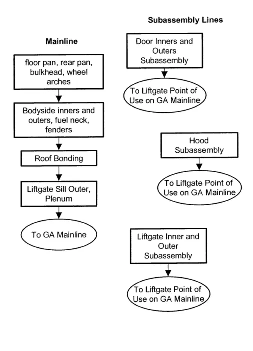
A basic process sequence for the bond shop is shown below in figure 3-3. As shown in this
process sequence map, multiple panels can be bonded onto the car at one time. For instance, the mainline starts off with all of the underbody parts being bonded on in one station. The wheel arches, floor pan, rear pan and bulkhead (dashboard) are all bonded on in one station using one fixture. The bonding fixture provides locating datums for the panels as well as the space frame, to ensure that the panels are positioned correctly on the car.
The doors and other closures are built up in a similar manner on separate lines. The door line in the bond shop receives a bent tube structure from the frame shop. This structure is sandwiched between the door inner and outer panels in a bonding fixture. The other components, such as the window, handles, lock mechanism, etc. are assemble into place before the door panels are bonded together.
For most of the bonding stations, duplicates of the bonding fixtures would be required to meet the plant's desired throughput. Development work would be required to determine the optimal bonding adhesive to use, based on the material chosen for the body panels. However, in similar bonding processes, it is not uncommon for the adhesive to be an epoxy that requires 7 to 10 minutes set time before it can be removed from the bonding fixtures. If the plant is producing
7 A stop-station conveyor is one that advances parts rapidly between stations and then has a set dwell time at each station before advancing them on again.
50,000 units per year, with a station cycle time of just over 4 minutes, it requires 2 or 3 of each
bonding fixture to achieve the required throughput in the bonding shop.
Figure 3-3: Bond Shop Process Sequence Subassembly Lines Mainline
floor pan, rear pan, bulkhead, wheel
arches
]
Bodyside inners and outers, fuel neck,
fenders
Roof Bonding
Liftgate Sill Outer, Plenum
To GA Mainline
Door Inners and Outers Subassembly To Liftgate Point of Use on GA Mainline Hood Subassembly To Liftgate Point of Use on GA Mainline
Liftgate Inner and Outer Subassembly
To Liftgate Point of Use on GA Mainline
One of the benefits of using an epoxy type adhesive to attach the body panels is that the adhesive can act as a liquid shim. All of the frames coming out of the frame shop are sure to have some dimensional variation to them. A limited amount of this variation can be compensated for by the epoxy. The bonding fixtures hold the panels in the proper location to ensure the completed car has good fit and finish.8 The epoxy adhesive can fill small gaps between the panels and the frame. Of course there are limits to how much variation the process can handle. It is still vitally important the framing fixtures are designed to provide a very high level of dimensional accuracy.
3.4 General Assembly Process Detail
The general assembly (GA) process for this type of space frame vehicle is very similar to a typical BFI general assembly line. At the time that the vehicle enters GA, it looks very similar to a BFI vehicle. In both cases, GA receives a complete, finished appearance body with all of the body panels painted and installed.
The doors of the car have not yet been attached to the body as it enters GA. They remain off to provide easier access to the interior of the car and to reduce the chance for damage. The first time they are attached to the car is near the end of the final assembly line. In most auto plants today, the doors are attached to the car before the paint shop. This ensures that they are painted at the same time and have the same final appearance. GA is sometimes performed with the doors remaining on, however, in most cases the doors are then taken off again at the beginning of GA.
8 Fit and finish refers to the final appearance of the product. A car that has good fit and finish has all of its parts
The assembly process is finished and then they are re-installed at the end of the line. With the manufacturing process explored here, all of the exterior body panels already have their final color and appearance when arriving to the bond shop. Therefore, there is no reason to attach the doors to the car at that earlier stage. They can be built up separately in the bond shop, with all of the door and window hardware installed, and then sent directly to their point of use near the end of the assembly line.
In the GA area, most of the assembly tasks can be performed on a moving car and powered conveyance would be used to maintain a constant flow. Upon entering GA, the car is mounted on what is known as an overhead chain-on-edge conveyor. This conveyor is chain driven and uses carriers that hang from the overhead rail and then reach underneath the car and provide points for the car to rest on. The car starts off at a height low enough to provide easy access to the interior and engine compartment areas. It can then be raised up in height to provide easy access to the underside of the car. At that point, the engine, transmission, suspension, etc. can be more easily assembled to the car. After completing the higher elevation work, the car can be dropped back down in height and set onto a flattop conveyor. This flattop conveyor is built into the floor of the plant and operates like a moving sidewalk. On the flattop conveyor there is no need for any type of carrier or cradle, so workers would have full access to the car. It is at this point that the doors can be easily installed.
As mentioned earlier, the parts assembled in GA are very similar to the parts assembled in GA of a BFI car. One difference could be in a slightly reduced part count because of fewer interior trim
pieces. If the interior body panels are textured composite panels, there is no need to cover them up with additional plastic trim pieces. They can provide the finished appearance.
The GA shop receives a few major subassemblies from suppliers outside of the plant. The rear suspension can be sub assembled so that it can be raised up and attached to the car as one single unit. The instrument panel inside the passenger compartment can also be sub assembled so that it can be installed into the car as one part. The engine arrives at the plant partially dressed.9 This reduces amount of prep work each engine requires before being installed into a car. These types of subassembly strategies are consistent with what is commonly seen in the automotive industry today. It allows for more of a modular type build in the final vehicle assembly plant.
3.5 Chapter Summary
This chapter has described the manufacturing process for bent tube space frame vehicles. It explained the overall assembly plant process flow and then provided more process details for the frame shop, bond shop and general assembly area.
The next chapter explores some of the body panel alternatives for a space frame vehicle. It describes four options that were considered for this project, discusses their advantages and disadvantages and offers a cost estimate comparison. It then chooses the most viable of the alternatives.
9 Engine dressing refers to the process of attaching the required components, such as hoses and wires, to the engine before it is installed in the vehicle.
CHAPTER 4 - BODY PANEL MANUFACTURING
4.1 Body Panel Materials Considered
The purpose of this project is to stretch the boundaries of what we think of as low investment automobile programs. For that reason, some non-traditional panel materials and processes are considered. This type of space frame vehicle could be constructed using traditional steel body panels on both the interior and exterior. However, steel panels, even if low volume tooling is utilized, still require a significant investment.0 The goal was to try avoiding or reducing this investment figure even further.
This project performed detailed analysis of four main panel strategy alternatives:
1. Open mold fiberglass, as used by the boat industry.
2. VEC@ Technology - a closed mold fiberglass process from Genmar, Inc."
3. A combination of composite technologies, including SMC, paint film and injection
molding.2
4. A hybrid strategy using steel panels and VEC@ Technology panels.
The chart shown in Figure 4-1 below illustrates why these four alternatives are investigated. The chart shows relative investment costs for the tooling to mold a set amount of parts in several composite processes. Assuming that the parts being molded are body panel type parts, it also estimates tooling cost for the equivalent steel stamping dies. This chart is not exact, does not include real numbers and would vary depending on the exact part being considered, but it does
10 Low volume tooling refers to the general category of tooling designs that decreases the required investment while typically making a sacrifice in cycle time.
" VEC = Virtual Engineered Composite
give an idea of the relative investment costs. When choosing which process to use for a particular part, many other design factors must be considered.
Figure 4-1: Body Panel Tooling Investment Comparison
4X
0)
S C)
Panel Forming Process
0
3X
2X
x
As shown in this figure, the composite processes chosen for further investigation offer the potential for very significant investment reductions compared to steel panels. The four panel strategies that are considered will be detailed further in the next four sections. Section 4.6 will then compare the investment cost estimates for each panel strategy as well as the expected piece price for a complete set of body panels. The investment figures are assumed to be approximately
equal between the U.S. and Mexico. However, the piece prices are adjusted to account for labor rate differences where appropriate.
4.2 Open Mold Fiberglass
The open mold, or hand lay-up, fiberglass process has been around for decades. It capitalizes on the tensile strength of glass fibers to provide reinforcement for a plastic resin. It has been used in the recreational boating industry since the 1950's and has changed little during that time. It is
also used sparingly in the automotive industry for aftermarket parts, specialty products and for some tractor-trailer cabs. However, it has never been used extensively in mass-produced
passenger cars. It has long cycle times and requires very inexpensive tooling so it lends itself to low volume applications.' While there are some limitations to the shape of parts that can be molded with open mold, a very wide range of sizes is possible.
The tools for open mold fiberglass parts are also made out of fiberglass themselves. A plug is made, typically out of wood, in the shape of the finished part's surface. This plug is then used to shape the fiberglass tools. Each tool has a relatively short life (1,500-2,500 parts) and a long cycle time (8 hours for a boat hull), so the plug can be used to create several tools in order to mold multiple parts at once or to replace spent tools.'4
Because it is an open mold process, only one tool is required to mold each part. The mold lies horizontal and the material for the part is applied to the top surface. The first material applied to the mold is either a gel coat or primer spray. This gel coat or primer will end up being the exterior surface of the final part, so the final part's intended application will determine which material to use. If it needs to be painted later, a primer coat will be used. If it is for an
application where a gel coat finish is desirable, there is no need for the primer. The appropriate
13 Cycle time is the amount of time required to complete a process. It is the elapsed time in between the start and
completion of a part.
color gel coat can be applied directly to the mold. Gel coat finishes are typically used on all fiberglass boats as well as a few other fiberglass applications. The gel coat is colored to provide the desired final appearance of the part being made. A gel coat does not provide a surface finish exactly like a modem automotive paint job, but it does give a paint-like appearance. For this analysis, it is assumed that a primer coat is used because a traditional automotive paint job is required to meet North American automotive consumer expectations for appearance and performance.
After the primer coat is applied, a barrier coat of resin is applied to separate the gel coat from the glass fibers and prevent bleed through of the glass fibers.1 5 After the barrier coat is in place, the glass fibers can be applied. The glass fibers are typically chopped into small pieces (on the scale of one inch) and mixed with resin before they are sprayed into the mold. Spraying on these chopped fibers results in random directional orientation so that the material has uniform strength and material properties in all directions.
Once the mold has been fully coated with the glass fibers and resin it is hand-rolled to ensure the fibers are lying flat and to remove air pockets. It then must be allowed to cure. Depending on the size and thickness of the part and whether or not curing ovens are used to provide heat, the part may require from one-half hour to eight hours before it can be removed from the mold. The part then must be pried loose from the mold and removed by hand. Excess material around the edges of the part is trimmed off to give the finished product.
15 Bleed through is a condition where an inner material of a product works up to the surface and becomes exposed.
In this case, bleed through would result in glass fibers working up to the surface of the panel and being exposed to the outside.
The open mold fiberglass parts can be molded with either a smooth surface or a textured surface. This process flexibility enables the use of open mold fiberglass for both interior as well as exterior body panels. For most exterior body panels, manufacturers want the smooth, shiny appearance that consumers are accustomed to. However, for interior panels, a textured finish is more appropriate for providing consumers with a comfortable, inviting passenger area. Molding these interior body panels with a textured composite can also be used to reduce the parts count for general assembly. Most cars today have steel inner body panels. This steel is then covered
up in most areas with plastic trim pieces. If the body panels are textured plastic to begin with,
most of these trim pieces can be eliminated.
As can be imagined from this brief process description, the open mold process is very labor intensive. It also has a very long cycle time. Curing ovens can be used to accelerate the drying process, but even with the use of ovens the cure time for automotive size panels would be much longer than the station cycle time on the vehicle assembly line. The panels would have to undergo some curing after the application of each material, with the longest cure time spent after the final application of the glass chop and resin. The total time through the panel molding process may be as long as 90 minutes. This would require that over 20 pieces of each panel part number might be required to be in process at any one time to keep up with the assembly line's production rate. This adds complexity and variation to the production system since each mold will not produce exactly duplicate parts.
The only parts of the open mold process that have been automated with much success are the spraying operations. Robots can be used to spray in the primer coat, barrier coat and resin/glass
chop mixture, as they are in some personal watercraft manufacturing. Fanuc, a major industrial robotics manufacturer, produces a robot system designed specifically for this purpose. Fanuc's AccuChop@ system is a process control package designed for automated fiberglass lay-up
applications. This type of automation offers a couple of advantages over manual spraying. It significantly reduces the need to expose workers to the highest level of styrene emissions. It also improves the consistency of the final product. The robot will move at a constant rate as it passes the spray nozzle over the mold, resulting in a consistent material thickness.
However, this automation does not have a significant effect on throughput. The nozzles and spraying equipment itself limits the speed at which a panel can be sprayed. Therefore, each robot can only do the same amount of work as one person. Each robot also requires some preventive maintenance and a technician to keep it operating properly. For this project analysis,
it was estimated that a bank of 28 robots would require 2 operators to perform cleanup and preventive maintenance between each shift. That same bank would also require the full attention
of one trained technician to deal with ongoing programming and electrical problems.
Figure 4-2 shows the results of financial analysis that was performed to determine if automating these spray processes is a good idea. Appendix 3 shows the spreadsheets used to perform that financial analysis. Figure 4-2 shows the payback period and net present value for this type of automation project. The analysis was performed for both United States production as well as Mexico production. It is assumed that these fiberglass panels would be purchased from a local
composite parts supplier, so labor rates for hand lay-up fiberglass operators in Michigan were used for the United States analysis. These labor rates were obtained from United States Bureau
of Labor Statistics sources. Labor rates for Mexico production were obtained from a report published by the Mexican Bank for Foreign Trade. General manufacturing labor rates were used
for this Mexico analysis. A more detailed spreadsheet from this analysis can be seen in Appendix 1.
Figure 4-2: Open Mold, Automation Analysis
United States Mexico
Assumed Cost of a Robot $70,000 $70,000
Labor Costs per Person $44,067 $8,914
Headcount Reduction -19% -19%
Payback Period 0.7 yrs 6.9 yrs
NPV Effect on 5-yr Program + $32 Million - $2.0 Million
As shown in the chart, the automation investment makes very good sense in the US labor market. The investment has a payback period of less than one year and positive net present value (NPV) when comparing the equipment costs to the labor savings. For Mexico production, the
automation is not a good investment. The payback period is greater than seven years and it has a negative NPV impact on the project. The cost of capital used for this analysis was set to match GM's current return on investment (ROI) for their vehicle operations. Capital committed to this type of low investment manufacturing operation could have been invested in more traditional programs that are assumed to match the company's current ROI.
Another major drawback of this open mold process is the environmental implications it has. The spraying processes are very messy and give off high levels of styrene emissions. Because the part is open to the environment as it cures, it also continues to give off styrene as the resin dries. These styrene emissions cause health concerns for the workers that are exposed to them and are regulated by the Environmental Protection Agency when given off in large amounts. Workers
involved in the spraying operations have to wear respirators and the emissions abatement
equipment requires a large investment. If a plant were producing all of the panels for this type of low volume automotive application, the abatement equipment would cost in the tens of millions of dollars.
The piece price estimates for open mold body panels are adjusted for the labor rate difference between the U.S. and Mexico. The tooling investment cost is considered to be negligible, due to the short life of the fiberglass molds. Each tool only has a life of a 1500-2500 parts and there would be an ongoing process of replacing the molds. Therefore, the tooling cost is considered a variable cost and is rolled into the piece price estimates.
4.3 VEC® Technology
VEC® Technology is a process owned by Genmar Holdings, Inc of Minneapolis, MN. Genmar
is the world's largest producer of recreational boats. They have been using the VEC@ process for the last few years to produce many of their boat hulls and decks, as well as some smaller parts. It produces a material that is very similar to the traditional open mold boat manufacturing, but it is a more consistent, higher-quality final product.
The VEC@ process is a closed mold fiberglass process. The molds themselves are also made with fiberglass skins. There is both a top and bottom mold skin, which provide the new part with its shape. These mold skins are sealed over the top of steel pressure vessels, which are then filled with water. Because the water in the pressure vessels is incompressible, it helps the mold