Designing a tokamak fusion reactor
—How does plasma physics fit in?
The MIT Faculty has made this article openly available. Please share how this access benefits you. Your story matters.
Citation Freidberg, J. P. et al. “Designing a Tokamak Fusion reactor—How Does Plasma Physics Fit In?” Physics of Plasmas 22, 7 (July 2015): 070901 © 2015 AIP Publishing
As Published http://dx.doi.org/10.1063/1.4923266
Publisher American Institute of Physics (AIP)
Version Author's final manuscript
Citable link http://hdl.handle.net/1721.1/111207
Terms of Use Article is made available in accordance with the publisher's policy and may be subject to US copyright law. Please refer to the publisher's site for terms of use.
June 2015
Plasma Science and Fusion Center Massachusetts Institute of Technology
Cambridge MA 02139 USA
This work was supported by the U.S. Department of Energy, Grant No. DE-FG02-91ER- 54109 and DE-FC02-93ER54186. Reproduction, translation, publication, use and disposal, in whole or in part, by or for the United States government is permitted.
Accepted to Physics of Plasmas (May 2015) PSFC/JA-15-21
Designing a Tokamak Fusion Reactor –
How Does Plasma Physics Fit In?
Designing a tokamak fusion reactor – how does plasma physics fit in?
J. P. Freidberg, F. J. Mangiarotti, J. Minervini MIT Plasma Science and Fusion Center Abstract:
This paper attempts to bridge the gap between tokamak reactor design and plasma physics. The analysis demonstrates that the overall design of a tokamak fusion reactor is determined almost entirely by the constraints imposed by nuclear physics and fusion engineering. Virtually no plasma physics is required to determine the main design parameters of a reactor: a R B T T p n, 0, 0, , , , ,i e tE,I . The one exception is the value of the toroidal current I , which depends upon a combination of engineering and plasma physics. This exception, however, ultimately has a major impact on the feasibility of an attractive tokamak reactor.
The analysis shows that the engineering/nuclear physics design makes demands on the plasma physics that must be satisfied in order to generate power. These demands are substituted into the well-known operational constraints arising in tokamak physics: the Troyon limit, Greenwald limit, kink stability limit, and bootstrap fraction limit. Unfortunately, a tokamak reactor designed on the basis of standard engineering and nuclear physics constraints does not scale to a reactor. Too much current is required to achieve the necessary confinement time for ignition. The combination of achievable bootstrap current plus current drive is not sufficient to generate the current demanded by the engineering design. Several possible solutions are discussed in detail involving advances in plasma physics or engineering.
The analysis thus provides a crisp, compact, logical framework that will hopefully lead to improved physical intuition for connecting plasma physic to tokamak reactor design.
1. Introduction
The purpose of this paper is to bridge the gap between fusion reactor design and plasma physics. The main goal is to show how plasma physics directly impacts reactor design. Our target audience is plasma physicists, and not reactor engineers. Indeed, many reactor engineers are already aware of the main results derived here, having deduced them from their own detailed reactor designs [1-8]. Unfortunately, these design results have by and large not permeated into the plasma physics community thereby providing the primary motivation for the present work.
Interestingly and perhaps surprisingly, our analysis demonstrates that the overall design of a standard tokamak fusion reactor is actually dominated by the constraints imposed by nuclear physics and fusion engineering. With one exception, virtually no input from achievable plasma physics performance is required to determine the main design parameters of the reactor: a R B T T p n, 0, 0, , , , ,i e tE,I . The one exception is the value of the toroidal current I , which depends upon a combination of engineering and plasma physics. The implication is that a reactor designed on the basis of engineering and nuclear physics constraints, combined with the one exception just noted, makes demands on the required zeroth order plasma physics performance that must be satisfied in order to generate power.
It is worth emphasizing this perhaps somewhat surprising result. A reactor based almost entirely on engineering and nuclear physics leads to design values very similar to comprehensive designs which do actually account for all plasma physics constraints. The engineering/nuclear physics design demands certain zeroth order performance from the plasma, without consideration of what is actually achievable.
We note that if currently achievable tokamak plasma performance just happens to meet these demands, the dominant plasma physics component of fusion power would be essentially solved. As might be expected, there are also a substantial number of
additional, less dominant plasma physics constraints that need to be simultaneously satisfied but, for the sake of simplicity these are not considered here. Even so, if the dominant plasma physics could be satisfied this would be a clear signal to the world’s fusion program to increase research on engineering and nuclear physics issues.
Unfortunately however, present-day plasma physics performance fails in one crucial area. The reactor-demanded value of I required to achieve a high enough t for E ignited operation is too large. Stated differently, the combination of presently
achievable current drive plus bootstrap current in a standard tokamak is too small to sustain the I needed for steady state ignited operation. This is a potential “show stopper” and a solution must be found if the tokamak is going to lead to a power producing reactor.
Several possible solutions are discussed. One class involves advanced plasma physics: increased energy confinement times, higher b limits, and increased current drive efficiency. A second class involves advanced engineering: increased maximum allowable magnetic field and demountable superconducting joints. This, in the opinion of the authors has the greatest likelihood of success. A third class relaxes some of the economically driven engineering constraints: larger power output or lower neutron wall loading.
To summarize, our main conclusion is that the basic as yet unsolved zeroth order plasma physics problem facing the tokamak is the
achievement of steady state operation in a high performance, reactor grade plasma. This is a critical goal that the US Fusion Program needs to focus on as fusion research moves forward.
Before proceeding there is one point worth discussing in order to properly set the stage for the analysis. As stated above, the intended audience for the paper is plasma
physicists. The reason is that the primary contribution of the present work is to show by means of simple, analytical calculations, how one can design a basic tokamak reactor. This has the important advantage of clearly demonstrating how plasma physics enters the reactor design; in other words the analysis provides valuable physical intuition for plasma physicists.
The deliberate simplicity of the analysis obviously makes the numerical accuracy of our results less than that of current state of the art reactor designs [1-8]. Even so, the numerical design parameters derived in our analysis are reasonable and plausible
compared to more detailed designs. Still, although the design values are reasonable, our main interest is in illuminating the reasons leading to the choice of these parameters.
The strategy of the analysis is to “design” a standard tokamak reactor based on nuclear physics and engineering constraints with only one direct input of plasma
physics. Here, “standard” refers to typical values of the engineering constraints used in the design of most US fusion reactors [1-3]. The authors recognize that designs in
Europe and Asia sometimes define “standard” differently than in the US [1-3] which can result in more optimistic conclusions. Still, for present purposes we focus on a standard design based on typical US criteria.
Once this design is completed the resulting plasma demands are calculated and then substituted into the well-known zeroth order operational constraints arising in tokamak physics: the Troyon limit, Greenwald density limit, kink stability limit, and maximum bootstrap fraction. The goal is to see whether or not the achievable plasma performance is capable of meeting the required demands. Unfortunately, as already stated, the plasma in a standard tokamak is not very cooperative. Too much current is required to achieve steady state operation thus motivating an investigation into various possible solutions.
Lastly, there is one caveat that needs discussion in order to keep the analysis in perspective. We do not quantitatively account for the critical plasma engineering
currently an unsolved problem that affects all fusion concepts, not only tokamaks, and is also a potential show stopper in its own right. To support this statement we note that the anticipated heat loads in a reactor are typically almost an order of magnitude larger than in current experiments (and even ITER). This is indeed a very serious problem.
Possible solutions have been suggested including the super-X divertor [10], the snowflake divertor [11], double null divertors [12-14], negative triangularity cross
sections [15], and liquid lithium collector plates [16]. However, there has not as yet been a successful experimental demonstration at high heat loads of any of these technologies. This is a task for the near future. Consequently, it is not possible at present to reliably quantify how the heat load problem directly enters the design of a reactor. Instead, we define a figure of merit which measures how difficult it will be to satisfy the heat load requirement. This figure of merit makes it possible to compare different design
strategies but in all cases it must be assumed that a satisfactory solution can be found.
2. Formulation of the design problem 2.1 The design goals:
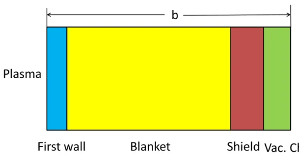
The aim of the design is to calculate the basic parameters of a tokamak fusion reactor as determined by the critical engineering and nuclear physics constraints plus the one-exception plasma physics needed to determine I . The reactor model is
illustrated in Fig. 1. The dominant components of the reactor are the plasma, blanket region (first wall, blanket, shield, and vacuum chamber), and toroidal field magnets. The analysis has also been carried out including the central solenoid, but the overall results are very similar and for the sake of simplicity this coil is ignored
Table 1. Reactor parameters to be determined.
The analysis presented in the paper yields reasonable values for all of these
parameters, comparable to far more sophisticated designs [1-8]. Even more important, the analysis gives a reason for determining all of these values. It is worth
re-emphasizing that the final design demands certain values for the plasma temperature, pressure, density, and current for a successful fusion reactor. These are not free parameters to be determined by the best efforts of plasma physicists.
2.2 Engineering and nuclear physics constraints:
Quantity Symbol
Minor radius of the plasma a
Major radius of the plasma R0
Elongation k
Thickness of the blanket region b
Thickness of the TF magnets c
Plasma temperature T
Plasma density n
Plasma pressure p
Energy confinement time tE
Magnetic field at R=R0 B0
Normalized plasma pressure b
Plasma current I
Normalized inverse current q*
There are a number of basic engineering and nuclear physics constraints that directly enter into the design of a “standard” tokamak reactor. The nuclear physics constraints, involving cross sections, are straightforward but the engineering constraints warrant some discussion. The values for the main engineering constraints are typical of those used in most fusion reactor designs [1-8]. Specifically, the electric power output is set to PE =1000 MW to maximize economy of scale benefits without overstressing grid capacity and/or deterring investor interest.
Another critical constraint is the maximum allowable neutron wall loading. Many designs typically assume 4 / 2
W
P » MW m . We recognize that some designs [17] use lower values, on the order of 1 2 / 2
W
P » - MW m , which in general leads to a larger, easier to build, but more expensive plant. However, even at this early stage of fusion reactor development many US designs often place a strong emphasis on perceived economics. In fact, D. Whyte has presented a calculation [18] that shows when
blanket/first wall replacement time and cost are taken into account economic breakeven is not possible unless a neutron wall loading of at least 3 5 / 2
W
P = - MW m is achievable. This crucial economic issue plays a major role in US designs, and further motivation by D. Whyte’s recent analysis leads us to choose an admittedly aggressive
value of 4 / 2
W
P = MW m for our standard reference reactor.
Similarly, most reactor designs place a strong demand on steady state operation [1-8]. In contrast, some designs [17, 19] consider the possibility of a pulsed reactor, an acknowledgement of the difficulty of achieving steady state operation. While pulsed operation alleviates the problems of achieving steady state, it introduces new
engineering problems associated with cyclical thermal and mechanical stresses. In the US steady state is currently considered to be the lesser of two evils and this is the choice made here.
A related constraint involving the overall power balance is the maximum allowable recirculating power fraction. Typically, an economically viable power plant recirculates
10% or less of its total electric power output. To ease this difficult constraint for fusion we allow a maximum recirculating fraction of 15% of which 10% corresponds to the current drive power needed for steady state operation.
Next, consider the magnets. The maximum allowable magnetic field, which occurs on the inboard midplane of the TF coil, is taken as Bmax =13 T, a realistic value for current state of the art Niobium-Tin superconducting TF magnets [4, 20]. Below this field the magnet should not quench. In terms of design there are two additional magnet engineering requirements: (1) the maximum allowable mechanical stress on the
supporting structural material is smax =600 MPa and (2) the maximum allowable current density averaged over the whole winding pack (i.e. superconducting cables plus mounting structure) is 2
max 20 /
J = MA m . The superconducting cables themselves carry a current density of 45 / 2
SC
J = MA m but it is the full winding pack that contributes to the size of the coil thickness c . These are typical values for large scale Niobium-Tin SC magnets and are very similar to the values for ITER [20].
The final quantity that needs discussion is the value of magnetic field in the center of the plasma. Specifically, a fundamental quantity that defines a tokamak is the magnetic field B =B0 at R=R0. Here there is a basic conflict between engineering and plasma physics. Engineering obviously would like B =0 0 to minimize the cost. On the other hand, plasma physics would like B = ¥0 to maximize performance.
The strategy adopted here assumes that B0 is a given fixed parameter but whose value is initially unspecified. In principle, we could design a sequence of reactors as a function of B0. The choice for B0 would then be the minimum value that satisfies all the plasma physics constraints. It is important though to make sure that the resulting
0
B does not lead to a field on the inboard side of the coil that exceeds the maximum allowable limit, which has been set to Bmax =13T . It turns out that the value of B0 for good plasma physics always exceeds the Bmax =13T limit. The practical
implication is that the value of B is set in any given design until the condition 0
max 13
B = T is reached.
Note that the constraint values described above, while typical, can vary somewhat from design to design. However, these variations are not critical to the basic design analysis. For convenience the engineering constraints plus the self-explanatory nuclear physics constraints are summarized in Table 2.
Quantity Symbol Limiting Value
Electric power output PE 1000 MW
Maximum neutron wall loading PW 4MW m/ 2
Maximum magnetic field at the coil Bmax 13 T Maximum mechanical stress on the magnet: smax 600 MPa Maximum superconducting coil current density
averaged over the winding pack
max
J 20MA m/ 2
Thermal conversion efficiency hT 0.4
Maximum RF recirculating power fraction fRP 0.1 Wall to absorbed RF power conversion efficiency hRF 0.4 Temperature at 2 max / v T s é ù ê ú ë û T 14 keV
Fast neutron slowing down cross section in Li-7 sS 2 barns
Slow neutron breeding cross section in Li-6 sB 950 barnsat 0.025 eV
Table 2. Basic engineering and nuclear physics constraints
Overall, it is fair to say that the constraints listed in Table 2 almost completely determine the reactor design and make no reference to plasma physics. As the analysis progresses we shall see that plasma physics actually enters the design in two ways.
First, the empirical energy confinement time will be directly used to calculate the current required for steady state operation. Second and indirectly, the need to achieve good plasma performance drives the design to high values of B . When these plasma 0 requirements are quantified, we shall see that achievable plasma performance is not very cooperative when it comes to reactor design.
Lastly, it is interesting for a moment to consider a somewhat different mission – a steady state pilot plan rather than a full scale power reactor. In this case, as shown by the ARC design [21], a combination of aggressive plasma physics, magnet engineering, and blanket design leads to a compact, high field device producing an output power of only 283 MW . Although the ARC recirculating power fraction is about fRP =0.3, it operates at a lower wall loading 2.5 / 2
W
P = MW m , and its absolute cost should be much smaller because of its lower power out. This last feature is a major advantage in minimizing the cost of fusion development. The present analysis with a noticeably different set of constraints could in principle be used to analyze pilot plant design. However, this analysis is deferred until the future.
2.3 Design strategy
Returning again to the full scale reactor we now determine the various quantities entering the design one by one. The basic strategy of the analysis is to express each design requirement in terms of the plasma minor radius a. After all the engineering and nuclear physics constraints have been taken into account, the resulting plasma demands are then compared to the achievable plasma performance as determined by years of experimental experience. This comparison is carried out as a function of a to see which if any values might lead to an attractive reactor.
As the analysis progresses typical values for each of the reactor parameters are estimated by choosing a such that R0 /a = , a standard value for a tokamak reactor. 4
There is no justification for choosing a this way – this is simply done to give readers a convenient reference design to keep in mind. The actual dependence of the reactor parameters on a is examined once all the requirements have been taken into account.
3 Geometric requirements 3.1 The plasma elongation k
The first step in the reactor design is determining the ellipticity k. This is a non-controversial choice which is made at the beginning of the analysis in order to simplify various geometric expressions that appear later in the analysis. The choice is non-controversial because the impact of larger ellipticity is favorable for both engineering and plasma physics. Ellipticity reduces the cost and improves plasma performance.
However, both plasma physics and engineering also place limits on the maximum achievable ellipticity in practical designs. The plasma physics limitations result from the onset of vertical instabilities when k becomes too large [22]. Engineering enters the picture through feedback, which can stabilize these instabilities within certain
engineering limits related to the practical design of control systems. That is, the growth rates of the instabilities, proportional to k , must be sufficiently low that practically achievable control systems can be designed with an adequately fast response time.
In the analysis that follows we choose
1.7
k = (1)
a value that has been readily achieved in existing experiments, is anticipated for ITER, and is typical in many sophisticated reactor designs. We recognize that this value may decrease somewhat as the aspect ratio increases but there is no simple, universally
agreed upon, engineering based functional relation of the form k k£ max( )e presently available. For simplicity we just set k =1.7 for all designs in our analysis.
3.2 The blanket region thickness b:
The “blanket” region consists of the first wall, blanket-and-shield, and vacuum chamber. Each of these components is assumed to be a toroidally homogeneous,
monolithic structure. A simple planar model of the region is illustrated in Fig. 2. The largest of these components is the blanket which is the main focus of the analysis in this section. The blanket consists of the following sub-regions: (1) a narrow region for
neutron multiplication, (2) a moderating region to slow down fast fusion neutrons, (3) a breeding region to produce tritium.
There are many options for the overall blanket design [23, 24]. One can use solid or liquid breeding materials; pure lithium or compounds containing lithium; water, helium, or liquid salts as a coolant; a variety of structural materials; a vacuum chamber location which can be either inside or outside of the blanket. In spite of this wide range of options there are several universal nuclear properties that set the geometric size of the blanket, which is about the same for all options. In fact it is not unreasonable to say that the entire scale of a fusion reactor is largely determined by the slowing down mean free path of 14.1 MeV neutrons in lithium. This point is demonstrated as the analysis progresses.
The calculation below presents a simple model for determining the width of the combined slowing down and breeding sub-regions. These are the dominant
contributions to the blanket size which is only slightly less than the overall width b. We begin by noting that the breeding cross section in Li-6 is very large, on the order of 1000 barns, for thermal neutrons. It is negligible for 14.1 MeV neutrons. Thus it is important to slow the 14.1 MeV fusion neutrons down to near thermal energies in order
to achieve effective breeding. Most of the energy conversion from fusion neutrons to steam takes place in the slowing down region.
For purposes of calculation, assume the blanket is composed of pure natural lithium. A beam of 14.1 MeV fusion neutrons impinges from the left. Slowing down is
dominated by collisions of high energy neutrons with Li-7 nuclei, the dominant component of natural lithium. The basic slowing down physics is determined by the energy balance relation for neutrons.
Once the neutrons have slowed downed they enter the breeding region. Breeding requires Li-6 which has a 0.075 fractional concentration of natural lithium. The basic breeding physics involves the mass balance relation for neutrons. Each time a slow neutron has a nuclear collision with an Li-6 nucleus, the neutron is lost and a tritium nucleus is born.
The governing equations for slowing down and breeding can be written as
0 (0) 14.1 Energy balance (0) Mass balance S BR dE E E MeV dx d dx l l = - = G = - G G = G (2)
Here E =mv2 / 2 is the neutron energy and
7
1 /
S N S
l = s is the mean free path for slowing down. The quantity 28 3
7 4.6 10
N = ´ m- is the number density of Li-7 and
S
s
is the slowing down cross section. Since slowing down collisions are basically hard sphere collisions a reasonable approximation is that s »S 2 barns = constant [25]. This corresponds to l =S 0.1 m.
In the mass balance equation G( )x =nv is the neutron flux, G is the input flux, 0 6
( ) 1 /
BR x N BR
l = s is the mean free path for breeding and 28 3
6 0.075 7 0.34 10
N = N = ´ m- is the number density of Li-6. For slow neutrons the breeding cross section can be reasonably well approximated by the following energy
dependent relation sBR( )x =sB
(
ET /E)
1/2 where s =B 960barns and ET =0.025eV[25]. Observe the large nuclear cross section for breeding at thermal energies.
Equation (2) can be easily solved for E x and ( )( ) Gx . The solution for G( )x can then be inverted to determine Dx, the blanket thickness required to reduce the input
neutron flux to a sufficiently low level G corresponding to essentially complete breeding b of the fusion neutrons. We shall assume that 5
0
/ 10
b
-G G = . The desired expression for
x D is found to be 0 ln 1 ln 0.9 S B b x l æçç b G ÷ö÷ m D = ç + ÷÷÷= ç G è ø (3)
where bB =(lB /lS)
(
EF /ET)
1/2 =710 and lB =1 /N6sB =0.003 m. The solution is not very sensitive to the value of Gb /G0 since it appears in a double logarithm.The blanket is about 1 meter thick. The full dimension b entering the analysis requires that we add to Dx the first wall thickness, the neutron multiplication region, the shield, and the vacuum chamber. Comparisons with much more sophisticated blanket studies [5, 26] using more realistic combinations of materials in the blanket plus a higher degree of optimization, suggest that a reasonable, perhaps slightly optimistic, value for the full dimension is approximately
1.2
b » m (4)
and this is the value used in the analysis that follows.
The parameter b has now been determined solely by nuclear physics constraints. There is not much that can be done to reduce this value and its value essentially sets the geometric scale for the whole reactor.
3.3 The wall loading limit R0 =R a0( ):
As stated, the goal of the mathematical analysis is to express all quantities of
interest as a function only of a and b. Since b is known this ultimately leads to a one parameter family of constraint requirements. Keeping this strategy in mind the next step is to determine a relationship between R0 and a from the neutron wall loading constraint.
The relationship is straightforward to derive. We simply equate the total neutron power resulting from fusion reactions to the maximum allowable neutron power passing through the first wall: Pn =P SW . Here (P MW is the total neutron power, n )
2
( / )
W
P MW m is the neutron wall loading limit, and 2 2 1/2 0
4 [(1 ) / 2]
S » p R a +k is the approximate surface area of the plasma.
The neutron power can easily be related to the electric power output of the reactor by recalling that Pn =
(
En /E PF)
F with En =14.1MeV , EF =22.4MeV , andF
P = the total thermal power output from neutron and alpha fusion reactions plus Li-6 breeding reactions. The thermal power is converted into electrical power output by means of a steam cycle with a thermal efficiency h =T 0.4: PF =PE /hT
Combining these results leads to the desired relationship between R0 and a,
1/2 0 2 2 1 2 1 7.16 4 1 n E F T W E P R m E h P a a p k é æ ö æ öù ê ç ÷÷ úç ÷÷ = êê ççèç + ø è ø÷÷ úúççç ÷÷= ë û (5)
The major radius scales inversely with a but is independent of B . For the reference 0 case which assumes that R0 /a = , we see that Eq. (5) implies that 4 a =1.34m and
0 5.34
3.4 The central magnetic field B0 =B a b0( , )
The toroidal magnetic field at the center of the plasma can be accurately
approximated from the well-known relation B Rf( )=B R0( 0 / )R . Since the magnetic field at the inboard side of the TF coil is set by the maximum allowable value of Bmax it follows that 0 max max 0 1 a b 1 0.14 ( ) 6.8 T B B B a a b R æ + ÷ö ç ÷ é ù ç = ç - ÷÷= êë - + úû = ÷ çè ø (6)
The central field is about one-half of the maximum field.
3.5 The coil thickness c =c a B( , 0):
The toroidal field (TF) magnets are a major component of the reactor and some care is needed to obtain simple but reliable values for the coil thickness. Each TF coil is assume to be a flat pancake magnet. The coils are in wedging contact with each other at the inboard side and there are obviously spaces separating the coils at the outboard side. We do, however, neglect TF ripple effects..
Our model assumes that the total coil thickness c is comprised of two contributions,
M J
c =c +c (7)
Here, cM represents the thickness of structural material needed to mechanically support the magnet stresses while cJ represents the thickness of the superconducting winding pack (i.e. superconducting cable plus mounting structure) required to carry the TF coil current.
Consider first the evaluation of cM. There are several forces that contribute to the TF magnet stress including the tensile force, the centering force, and the out of plane bending force. The largest contributions arise from the centering force and tensile force and thus for simplicity, the bending force is hereafter neglected. The strategy is to separately calculate the stresses due to the tensile force plus the centering force and combine them to form the Tresca stress which is then set equal to the maximum allowable stress. Use of the Tresca stress is made for convenience since it leads to a simple analytic expression for cM. Keep in mind that the maximum allowable material stress for high strength cryogenic structural materials is on the order of 600 MPa [27]. This value is not conservative but should be achievable, even with presently availability high strength alloys.
The quantity cM is now calculated as follows. To begin, consider the effect of the tensile force. We split the TF magnet into an upper and lower half as shown in Fig. 3a and calculate the upward force on the top half of the magnet due to the magnetic field. Interestingly, as is well known [28], this force is independent of the magnet shape and only depends on the mid-plane dimensions of the coil. The upward force, expressed in terms of B0 is given by 2 2 0 0 0 1 ln 1 B Z B F p B R e n e æ + ö÷ ç ÷ ç = ç ÷ ÷÷ ç -è ø (8) where e =B (a +b) /R0.
Next, note that the upward force FZ is balanced by two equal tensile forces FT at each end of the upper half of the TF magnet. In other words FZ =2FT. Equality of the forces is assumed for mathematical simplicity. In actual detailed designs the inner leg force is slightly higher than the outer leg force but this effect is neglected here. We
further assume that the TF coil is designed to have approximately constant tension around its perimeter so that c =M constant around the magnet.
Using the assumption that neighboring coils are in wedging contact with each other on the inboard side it is then easy to calculate the total tensile force produced by the N magnets. We find 2 2 0 0 ( ) ( ) T T T T M F =s A =ps éëêR - -a b - R - - -a b c ûùú (9)
where s is the portion of the maximum stress T s balancing the tensile forces. max Both terms in the tensile stress force balance relation have now been calculated. After setting FZ =2FT we solve for s obtaining T
2 0 0 ln[(1 ) / (1 )] 2 (2 2 ) B B T M B M B e e s n e e e + -= - - (10) Here, e =M cM /R0.
A similar calculation holds for the centering force. The rectangular model for the magnet shape leads to a simple expression for the inboard and outboard radial forces over a narrow toroidal wedge of coil of angular extent D as shown in Fig. 3b. f
2 0 0 0 2 0 0 0 2 ( ) 2 2 2 ( ) 2 2 in B M out B M B a b R F B a b R F k f n e e k f n e e + D = - -+ D = + + (11)
The net inward force is just FR =Fin -Fout.
The force F is balanced by the compression stress due to wedging on the inboard R F is given by
2 ( )
C C C C M
F =s A = s c ka+b (12)
where s is the portion of the maximum stress C s balancing the centering force. max Equilibrium force balance requires that FR =2FC sin(Df/ 2)»FCD which leads to an f expression for s that can be written as C
2 2 0 0 0 0 2 1 2 1 2 2 2 2 2 2 2 1 B M B C M B M B M M B M B B e e B e s n e e e e e n e e e e æ öæ÷ + ö÷ æ öæ÷ ö÷ ç ÷ç ÷ ç ÷ç ÷ ç ç ç ç = ç ÷÷ç ÷÷» ç ÷÷ç ÷÷ ÷ ÷ ÷ ÷ ç - - ç + + ç - - ç + è øè ø è øè ø (13)
For mathematical simplicity, the second form neglects e in the second parenthesis, a M good approximation since e is usually substantially smaller then 2M e .B
The quantity e is now determined by setting the Tresca stress, M sT +sC , equal to its maximum allowable value, s ; that is max sT +sC =smax. The result is a quadratic algebraic equation for e . A straightforward calculation yields an expression for M
0 M M c =e R ,
{
2 1/2}
0 2 0 0 max 1 (1 ) 2 1 1 ln 1 2 1 M B B M B B M B B c R B e e b e e b n s e e é ù = - -êë - - úû é æç + ö÷ù ê ç ú÷ = ê + ç ÷ú ÷÷ ç + è - ø ê ú ë û (14)For the reference case cM =0.39m.
The final quantity to be calculated is cJ, the thickness of superconducting winding pack required to carry the current. This quantity is also most easily calculated at the inside of the magnet where the field is maximum. Since adjacent coils are in contact with one another this provide a total current carrying area equal to A as defined in Eq. (9). The current I passing through this area can be expressed in terms of
2 max 20 MA/m
J » , the maximum allowable overall current density for the
superconducting coils [1,20]: I =JmaxA. At the inside of the coil, I produces a toroidal magnetic field Bmax =n0I / 2 (p R0- -a b). We now make use of the fact that
max 0 / (1 B)
B =B -e . Simple elimination then yields an expression for cJ in terms of the geometry and B0,
{
2 1/2}
0 0 0 0 max 1 (1 ) 2 J B B J J c R B R J e e b b n é ù = - -êë - - úû = (15)For the reference case cJ =0.575m.
Based on this discussion the value of the total TF magnet thickness is written as
{
1/2 1/2}
2 2
0 2(1 B) (1 B) M (1 B) J
c =R -e -ëêé -e -b ùúû -ëéê -e -b ûùú (16)
The total reference value for the magnet thickness is c =0.965m
In terms of the geometry, at this point in the analysis the ellipticity k and blanket region thickness b have been determined. In addition, the major radius R and TF coil 0 thickness c have been expressed as a function of a . These relations do not depend on plasma physics, only the engineering and nuclear physics constraints previously
discussed. The next task is to see how these constraints place demands on the plasma physics performance.
By combining the geometric relations above with the remaining engineering
constraints it is straightforward to calculate the required plasma temperature, pressure, density, and energy confinement time as well as the plasma b , all as a function of a. With the addition of some plasma physics it is also possible to calculate the plasma current, the kink safety factor, and the bootstrap fraction. There is additional plasma physics involving ELMs, profile effects, energetic particle effects, etc. We view these effects as important but not dominant in terms of reactor design and thus, for the sake of simplicity, they are not explicitly considered in our analysis which proceeds as follows.
4.1 The average plasma temperature T
We assume that the plasma operates at a sufficiently high density so that
e i
T =T ºT . Thus, the fusion power density produced in the plasma is given by
2 3 2 1 ( ) / 16 P n v S E E p W m T b s = + (17)
where p =2nT . As usual we maximize SP by maximizing the ratio of sv /T2. This
maximum occurs at T »14keV . It actually has a relatively flat maximum at these temperatures so one can change this value somewhat without much penalty. In any event, for present purposes we choose
14
T = keV (18)
4.2 The average plasma pressure p
The plasma pressure is determined by the requirement that the total thermal power generated by fusion reactions in the specified reactor geometry produces the required electrical output power. All the fusion power, including the 4.8 MeV per breeding reaction with Li-6, is converted into steam which is then transformed into electricity with a thermal efficiency h =T 0.4. Thus, power balance (with EF =22.4MeV) requires 2 2 16 T F E v E p d P T s h =
ò
r (19)To evaluate the integral, plasma profiles must be specified. We make the important assumption that that the profiles have simple, standard forms. No large internal or edge transport barriers are allowed in this part of the analysis. The profiles are given by 2 2 2 2 3/2 2 2 1/2 (1 )(1 ) 2 (1 ) (1 )(1 ) 2.5 (1 ) (1 )(1 ) 1.5 (1 ) T p n T p n T T T p p p n n n n n n n r r n r r n r r = + - = -= + - = -= + - = -(20)
Here, R =R0 +arcosq, Z =k ra sinq, and an over-bar denotes average value. The plasma lies in the region 0£ £ . Note that the relation r 1 p =2nT implies that
2[(1 T)(1 n) / (1 p)] 2.4
p = +n +n +n nT = nT andnp =nT +nn. The quantities
, ,
T p n
n n n are free parameters which for standard profiles have been chosen as
1, 3 / 2, and 1 / 2
T p n
2 3 4 0 1 2 3 4 exp (ln ) (ln ) (ln ) (ln ) v k k T k T k T k T s = éêë + + + + ùúû (21) where k = -0 60.4593, k =1 6.1371, k = -2 0.8609, k =3 0.0356, and k = -4 0.0045. These assumptions are substituted into Eq. (19) leading to an expression for the required average pressure,
1/2 2 2 2 2 1 2 2 0 0 1 4 1 (1 ) n T E p T F P T p E R a n v d n n p h k r s r r é ù æ ö æ ö ê ç + ÷ ç ÷ ú ê ç ÷ ç ÷ ú = êê çèçç + ÷ø÷÷ èçç ÷÷ø÷ úú -ê ú ë
ò
û (22)All the quantities on the right hand side are either known or expressible in terms of a . After a straightforward numerical evaluation of the integral we obtain
1/2
8.76
p atm
a
= (23)
Observe that the pressure scales as a-1/2 but is independent of 0
B . For the reference case p =7.57atm. In terms of plasma physics parameters the required beta
corresponds to 0 2 1/2 2 0 2 1.31 % (1 B) p B a n b e = = - (24)
and has the value b =4.13 %.
The average plasma density is easily obtained from the relation p =2nT and is given by 20 3 1/2 1 1.66 (10 ) 2(1 )(1 ) p T n p n m T a n n n -é + ù ê ú = ê ú = + + ê ú ë û (25)
The reference value is n =1.43 10´ 20 m-3.
4.4 Energy confinement time tE
The energy confinement time is determined by the requirement that in steady state the thermal conduction losses are balanced by alpha particle heating. The plasma is assumed to be ignited. This power balance can be written as
3 3 2 2 P E E V p Pb pd t t =
ò
r= (26) where Pb =(Eb/EF)(PE /hT) and 2 2 0 2 PV = p R a k. Solving for t leads to E
2 2 1/2 0 3 F T 0.81 sec E E E R a p a E Pb h t = p kæççç ö÷÷÷ = ÷÷ çè ø (27)
The required energy confinement time scales as a and is also independent of 1/2 0
B . For the reference case t =E 0.94 sec.
All of the required plasma parameters have so far required no direct input from plasma physics. If we now combine an important plasma physics constraint with the engineering requirement on t we can derive an expression for the current E I in terms of a , in addition to a subsidiary relation for the bootstrap fraction f . This is where B the plasma physics enters the reactor design.
The plasma current is determined by equating the required energy confinement time to the empirically determined energy confinement time. For ELMy H-modes the
empirical t is given by [29] E 0.93 1.39 0.58 0.78 0.41 0.15 0.19 0 0.69 0.145 sec E I R a n B A H Pb k t = (28)
Here, all quantities have been previously defined except A =2.5 which is the average atomic mass and the H-mode enhancement factor H which for now is set to unity:
1
H = . Also the units are I MA , ( ) n(1020m-3), and (P MW)
b . We substitute Pb from
Eq. (26) and solve for I . The result is
0.74 1.08 1.63 1.08 1.49 0.62 0.84 0.44 0.16 0.20 0.16 0 0 0 7.98 E E 12.1 F T E P a I MA E H R a n B A B b t h k éæçê ö÷ ùú ÷ ç = êç ÷ ú = ÷÷ çè ø ê ú ë û (29)
The required current scales approximately as a and is nearly independent of 5/3 0
B . For the reference case I =14.3MA. In terms of the kink safety factor the current is
equivalent to 2 2 1.37 1.16 0 * 0 0 0 2 1 0.112 2 a B q a B R I p k n æ + ö÷ ç ÷ = çç ÷÷= çè ø (30)
with a reference value q =* 1.56.
4.6 The bootstrap fraction fB
The required bootstrap fraction follows from a simple analysis of current drive efficiency and the constraint that the RF recirculating power be (less than) 10% of the electrical power out: fRP =PRF /PE =0.1. Since current drive efficiency, even at its highest, is still relatively low, this is the dominant contribution to the recirculating power. For our reactor the current is driven by lower hybrid waves, launched from the outside, which have the highest efficiency as compared to other driving mechanisms.
Since PE =1000MW we see that PRF =100MW is available to drive current. Of this 100 MW we assume that there is a 50% conversion efficiency from wall power to klystron power and that 80% of the total klystron power is absorbed in the plasma for driving current. Therefore, the power that actually drives the current is equal to
(0.5)(0.8)(0.1) 40
CD RF RF RF RP E E
P =h P =h f P = P = MW.
Now, a reasonable approximation for the amount of current that can be driven per watt of absorbed power is given in terms of the local current drive efficiency hCD
[30-32] 0 2 1/2 1/2 2 2 2 2 1.2 n n 1 1 CD CD CD pe pe LH e e R nI P h w w w w = » æ ö æ÷ ö ç ÷ ç ÷÷ ç ç » W + +çèçç W ÷÷ø÷÷ çèç - ÷÷÷ø (31) where 2 2 2 2 ( ) / (1 / ) LH pi pe e
w r =w +w W is the square of the lower hybrid frequency, n is the parallel index of refraction, and the units are (1020 3), ( ),
CD
n m- I MA and ( )
CD
constraints corresponding to the avoidance of parametric decay instabilities (PDI). The value for this frequency is given by [30] w »2wLH( )rm with r »m 0.8 being the
approximate desired location of the peak electron Landau damping for reactor-like temperatures. Also, to evaluate these expressions we set the density n =n( )rm and, for an outside launch, B =B R[ (10 +erm)]=B0 / (1+erm).
The density n and magnetic field B have already been expressed in terms of a0 from Eq. (25) and the relation B0 =Bmax(1-eB). This in turn leads to a
straightforward although complicated algebraic relation for n =n ( ) a . In the analysis that follows the actual expression for n ( ) a is used to numerically evaluate the current drive efficiency. However, for reference case it is worth noting that typically n =1.67 corresponding to 0.43 / - 2
CD MA MW m
h = . Using these reference values it follows that the absorbed RF power can drive a current ICD =2.25MA, which turns out to be only a small fraction of the required current. Lastly, note that by combining the expression for n ( )a with previously derived results we can easily derive an expression for the bootstrap fraction 2 0 ( ) ( ) 1 1 1.2 ( ) n CD CD B I a P f a I a R nI = - = - (32)
For the reference tokamak, f =B 0.84.
4.7 Two additional figures of merit
The design discussion closes with the evaluation of two additional figures of merit, one related to cost and the other to heat flux. The absolute numerical value of these parameters is not very critical. However, they are useful when making comparisons
with the different design options discussed in future sections. The definitions of these parameters are as follows.
• The cost parameter
A simple but qualitatively correct measure of cost, originally introduced by Spears and Wesson [33], is the ratio of the volume of highly engineered reactor components to the electric power out. A larger volume of engineered components implies a larger absolute cost. Also, the key parameter is not the absolute cost, but the cost per watt. Hence, the ratio VI /P is introduced as the cost parameter, where E V includes the I volume of the blanket region and the TF coils. A short calculation leads to
2 2 0 0 2 ( )( ) 4 (2 2 2 )[(1 ) 2 ] I B TF E E B TF V V V P P V R a b a b a V c R a b c a b c p k k p k + = é ù = êë + + - úû = - - - + + + (33)
For the reference reactor we obtain / 1.00 3 /
I E
V P = m MW.
• The heat flux parameter
In a reactor the alpha power is converted into heat which is eventually lost from the plasma core by means of thermal conduction. This power represents the heat loss from the plasma. It enters the scrape-off layer, largely at the outboard midplane, where it flows essentially parallel to the field and is ultimately dissipated by a combination of expanded contact with the divertor plates and radiation resulting from detachment.
The critical figure of merit is defined by noting that if all the heating power were to be lost by a purely poloidal flow in the scrape-off layer, the corresponding poloidal heat flux in the large aspect ratio limit would be given by hp »Pb / 2p lR0 q where l is the q width of the scrape-off layer. Empirical evidence has shown the surprising result that
1 /
q Bp
l µ independent of geometry [34, 35]. Here B is the poloidal magnetic field at p the outboard midplane.
Now, the heat flux is not lost poloidally, but instead along the magnetic field. Thus, the power that must be safely dissipated is given by h »( / 2 )L pa hp =(R q0 a / )a hp
with qa »aB0/R B0 p the edge safety factor. These results can be combined into a simple figure of merit which is a measure of the parallel heat flux that must be dissipated 0 0 0 0 E f T P B E P B Q R E R b b h æ öæ ö÷ ç ÷ç ÷÷ ç ç = =èççç ÷÷÷øççè ÷÷÷ø (34)
Typical values of (Q MW T m - / ) for existing experiments with Pb replaced by Pheat are as follows: DIII-D = 40, JET = 45, Alcator C-Mod = 65. For ITER the expected value (using Pb) is ITER = 130. For recent reactor studies [3] the design requirements are ACT1 = 390, ACT2 = 570 . For the reference design presented here we find
499 - /
Q = MW T m.
5. How well does the plasma perform?
We now know what engineering and nuclear physics requires from plasma
performance for a standard tokamak reactor. The next question to ask is whether or not the plasma can be expected to meet these requirements assuming its performance is constrained to lie within well-established operational limits determined over years of
experimental operation. To answer this question we focus on four basic tokamak operational limits: (1) the Greenwald density limit, (2) the Troyon beta limit, (3) the kink safety factor disruption limit, and (4) the achievable bootstrap fraction. The comparisons between required and achievable values are discussed in the follow-on subsections.
5.1 The Greenwald density limit
The Greenwald limit [36] is given by
2 G I n n a p < º (35)
Substituting numerical values for the reference reactor leads to the requirement that
1.43<2.56 (36)
The Greenwald density limit is satisfied by a substantial safety margin.
5.2 The Troyon beta limit
The maximum achievable beta in a tokamak plasma is given by the Troyon limit [37] 0 2.8% T N N I aB b <b ºb b = (37)
After again substituting the reference numerical values we obtain the requirement on b that
4.13<4.39 (38)
The Troyon beta limit is satisfied but only just barely. There is not much safety margin.
5.3 The kink safety factor limit
To avoid current driven major disruptions the kink safety factor must satisfy [38-40]
* K 2
q >q » (39)
Substituting values from our reference reactor design yields
1.56>2 (40)
The required q lies below the minimum achievable value. The plasma current needed * to produce the required confinement time is just too large with respect to the allowable current for disruption avoidance. In other words disruption avoidance is a major
problem for our standard tokamak reactor. Possible cures for this problem are discussed shortly.
A short calculation is required to determine the maximum achievable bootstrap fraction. The analysis proceeds as follows. For simplicity we consider a large aspect ratio circular cross section tokamak with minor radius aˆ. To model elongation we assume that aˆ=k1/2a in order to preserve the total cross sectional area. It is also assumed that Te =Ti = and T Z =1. Under these assumptions the expression for the local neoclassical bootstrap current can be written as [29]
1/2 0 1 3/2 2 1/2 1/2 0 3/2 2 1/2 1/2 1/2 0 1 1 ( ) 2.44 0.055 (1 ) 4.88(1 )( 0.055 ) ˆ (1 ) 6.8 ˆ p B p n T r p n T J R B n r T r p B a R p B a R q n q q r r r n n n r r -æ ö æ÷ öæ÷ ¶ ¶ ö ç ÷ ç ÷ç ÷÷ ç ç = - ç ÷÷ ç ÷÷ççç + ÷÷ ÷ ÷ ç ç è ¶ ¶ ø è ø è ø é ù -ê ú = ê + + ú ê ú ë û é ù -ê ú = ê ú ê ú ë û (41)
Here, r =r a/ˆ and the last two expressions use the profiles given in Eq. (20). To complete the evaluation of the bootstrap current density the profile of Bq
resulting from the total current must be specified. Since lower hybrid heating occurs off axis near the plasma edge (i.e. typically r a/ ˆ00.8) we model the total current density
( )
T
J r with the relatively simply expression
1/4 2 2 9 (1 ) ( ) 8 ˆ 1 x T I x e J a e b b r b r p b æ ö é÷ - ù ç ÷ê ú = çç ÷÷ê ú ç -è ø ë û (42)
where r =x4/9 and b =2.53. Also, for simplicity we have ignored the need for a seed current on axis. A plot of JT( )r is illustrated in Fig. 4. Equation (42) can be easily integrated yielding the necessary relation for Bq( )r ,
0 ( ) 1 (1 ) 1 ( ) ˆ / 2 1 x B x e b I a e b q q b r b b b r n p r b é + - - - ù ê ú = = ê ú -ë û (43)
The desired expression for the achievable neoclassical bootstrap fraction is obtained by substituting Eq. (43) into Eq. (41) and then carrying out a simple numerical
integration over the plasma cross section.
5/2 5/4 1 5/2 2 1/2 1/2 2 0 0 0 (1 ) 268 B NC I a p f d I R I bq k r r r n æ ö÷ é - ù ç ÷ ê ú ç = = ç ÷÷ ê ú ç ÷ è ø
ò
êë úû (44)To achieve steady state operation the achievable bootstrap fraction must equal or exceed the required bootstrap fraction. This criterion reduces to
NC B
f > f (45)
which for the reference reactor translates into
0.44> 0.84 (46)
We see that the criterion is violated by a large margin. A standard tokamak cannot generate a large enough bootstrap current to maintain steady state operation.
5.5 The overall conclusion with respect to plasma performance
The analysis has shown that our reference tokamak plasma with standard profiles and a limiting magnetic field at the coil of Bmax =13T satisfies the Greenwald density limit and the Troyon beta limit. However, the required plasma current violates the kink disruption limit. Equally important, the achievable bootstrap current is far below the
required value for steady state operation. The difficulties with plasma performance all trace back to the need for a high plasma current to achieve a sufficient t for ignited E operation.
The above conclusions have been based on numerical values obtained from the reference design which assumes that R0 /a = . The conclusions are in fact more4 general. To see this we have repeated the entire analysis just presented but now allow a to be a free parameter. We then ask whether or not there is any value of a for which all the plasma physics demands can be simultaneously satisfied.
A convenient way to understand the analysis is illustrated in Fig. 5. Shown here are curves of (a) the required density/Greenwald density /n n , (b) the required G
beta/Troyon beta /b b , (c) the minimum achievable kink safety factor/required kink T safety factor qK /q , and lastly (d) the required bootstrap fraction/neoclassical *
bootstrap fraction fB /f , all plotted as a function of a . Each of these quantities must NC be simultaneously less than unity (i.e. lie in the unshaded region) for a successful
reactor. We see that this can never occur for any value of a !
The conclusion is that the absence of steady state and the excitation of disruptions are potential “show stoppers” for the standard tokamak. Ways must be found to reduce the required current in order resolve these problems. In other words, based on our definition of “standard” there is no zeroth order self-consistent tokamak reactor design that simultaneously accounts for engineering, nuclear physics, and plasma physics.
This important conclusion was reached independently several years ago by Manheimer [41, 42] also using relatively simple models and what he describes as “conservative design rules”. His proposed solution is not to focus on improvements in plasma physics and fusion technology as advocated in the AIRES studies and in the analysis presented here. Instead, his focus is on a potentially less demanding mission – the production of fission fuel by means of a fusion-fission hybrid.
6. Possible solutions
We discuss four possible approaches to resolve the problem of too much required current relative to achievable current. The first approach involves advanced plasma physics, the second involves advanced engineering, and the third and fourth involve relaxing a primary engineering constraint. The basic issues are first described qualitatively and then quantified by means of analysis.
6.1 The plasma physics approach – raise H
The first approach attempts to resolve the problem by means of advanced plasma physics, namely by assuming methods can be developed to increase the achievable energy confinement time. In terms of the analysis this is equivalent to increasing the value of the H-mode enhancement factor H. Practically this may be achievable by means of advanced tokamak (AT) operation in which profile control leads to the formation of appropriately located internal and edge transport barriers [43-45]. If successful, this approach has the advantage of leaving the reactor geometry and magnetic field essentially intact – the cost per watt remains unchanged, a major
advantage. There is no cost penalty. There are, however, other disadvantages. Raising
H lowers I , which while good for achieving steady state, is bad for the Greenwald density and Troyon beta limits both of which are lowered. Almost always the Troyon beta limit is violated requiring operation at b substantially above 2.8%. MHD N stability then requires feedback stabilization, a possible but not as yet routine
experimental mode of operation. Also, increasing H depends on controlling the current and pressure profiles by means of external power sources. This may become
The reactor design analysis for the plasma physics approach is straightforward. The calculations in sections 4 and 5 are repeated treating the H-mode enhancement factor H as a free parameter. For each value of H the plasma radius a is chosen so that
required bootstrap fraction is equal to the achievable bootstrap fraction: fB = fNC . This additional constraint leads to a unique value of a for the given value of H . Once this critical a =a H( ) is determined, the plasma performance criteria can be evaluated. The goal is to see whether or not there are values of H for which all plasma performance criteria are satisfied.
The results of this analysis are illustrated in Fig. 6. Shown here are curves, all for
max 13
B = T , similar to Fig. 5 with H now the variable along the horizontal axis. Recall that each of these quantities must be simultaneously less than unity (i.e. lie in the unshaded region) for a successful reactor.
We see, unfortunately, that there is no value of H for which all the remaining plasma performance criteria are simultaneously satisfied. Specifically, H =1.26 is the lowest enhancement factor at which the kink stability criterion is satisfied. At this value the Greenwald limit is still satisfied. However, the Troyon limit is now violated. To resolve this problem the allowable beta limit, as defined by b , would also need to N be increased, by a factor of 1.29; that is, b must increase from 2.8 % to 3.6 %. N
Further increases in H only make things worse as the beta limit is even further violated. Also the required enhancements in H and b are found to be noticeably larger than N the above values in more realistic designs that include safety margins [3]. For instance the ACT-1 advanced tokamak design requires H =1.65 and bN =4.7.
Note also that at H =1.26 the two figures of merit have the values 3
/ 1.07 /
I E
V P = m MW and Q =507MW T m- / . Both of these values are essentially identical to the reference case. As anticipated there is no penalty in either cost or heat load for the advanced plasma physics option.