HAL Id: hal-01855795
https://hal.archives-ouvertes.fr/hal-01855795
Submitted on 8 Aug 2018
HAL is a multi-disciplinary open access
archive for the deposit and dissemination of
sci-entific research documents, whether they are
pub-lished or not. The documents may come from
teaching and research institutions in France or
abroad, or from public or private research centers.
L’archive ouverte pluridisciplinaire HAL, est
destinée au dépôt et à la diffusion de documents
scientifiques de niveau recherche, publiés ou non,
émanant des établissements d’enseignement et de
recherche français ou étrangers, des laboratoires
publics ou privés.
Evidence of an information leakage between logically
independent blocks
Loïc Zussa, Ingrid Exurville, Jean-Max Dutertre, Jean-Baptiste Rigaud,
Bruno Robisson, Assia Tria, Jessy Clediere
To cite this version:
Loïc Zussa, Ingrid Exurville, Jean-Max Dutertre, Jean-Baptiste Rigaud, Bruno Robisson, et al..
Evi-dence of an information leakage between logically independent blocks. Second Workshop on
Cryptog-raphy and Security in Computing Systems (CS2’2015), Jan 2015, Amsterdam, Netherlands. pp.25,
�10.1145/2694805.2694810�. �hal-01855795�
Evidence of an information leakage between logically
independent blocks
Loic Zussa
´
Ecole des Mines de St ´Etienne
Gardanne, France
[email protected]
Ingrid Exurville
CEA-Tech PACA Gardanne, France[email protected]
Jean-Max Dutertre,
Jean-Baptiste Rigaud
´Ecole des Mines de St ´Etienne
Gardanne, France
[email protected]
Bruno Robisson, Assia Tria
CEA-Tech PACA Gardanne, France
[email protected]
Jessy Clediere
CEA Grenoble, France[email protected]
ABSTRACT
In this paper we study the information leakage that may exist, due to electrical coupling, between logically independent blocks of a secure circuit as a new attack path to retrieve secret information. First, anAES-128 has been implemented on aFPGAboard. Then, thisAESimplementation has been secured with a delay-based coun-termeasure against fault injection related to timing constraints vi-olations. The countermeasure’s detection threshold was supposed to be logically independent from the data handled by the crypto-graphic algorithm. Thus, it theoretically does not leak any infor-mation related to sensitive values. However experiments point out an existing correlation between the fault detection threshold of the countermeasure and theAES’s calculations. As a result, we were able to retrieve the secret key of theAES using this correlation. Finally, different strategies were tested in order to minimize the number of triggered alarm to retrieve the secret key.
Keywords
Delay-based countermeasure, information leakage, ’DPA-like’ anal-ysis, side effects
1.
INTRODUCTION
Security is a key component for information technologies and communication. Among the security threats, a very important one is certainly due to the vulnerabilities of the integrated circuits that implement cryptographic algorithms to ensure confidentiality, au-thentication or data integrity. These electronic devices could fall into the hands of malicious people and then could be subject to physical attacks.
Three different kinds of techniques are used to perform such at-tacks. The first one consists in getting information about the chip design by direct inspection of its hardware structure. The second technique consists in observing some physical characteristics (such as power consumption, electromagnetic radiation, response time, etc.) which change during the circuit’s computation. The third technique consists in disrupting the circuit’s behaviour by using fault injection means such as laser beam, voltage or clock glitches, electromagnetic pulses, etc. With such techniques the attacker may be able to: bypass the security functions (such as thePINcode
ver-.
ification), retrieve the details of their implementations, find out the manipulated data (cryptographic materials, personal data, etc.).
Somes techniques of key recovering are based on side channel measurements. The first one, calledDPA-like, consists in building a set of mathematical models (i.e. mathematical formulæ) from a prioriknowledge about the circuit. Each model is associated with a hypothesis on the value of the key. Then, the models are com-pared with measurements. The model which matches the best with measurements is generally associated with the right key hypothesis [1]. The second kind of side channel attacks needs a profiling step on another circuit. This circuit is supposed to be identical to the target and the attacker is supposed to be able to set the key value. In this case, the profiling step is used either to improve the model a priori(stochastic attacks, [2]) or to build a statistical model only based on measurements (template attacks [3]).
To reduce sensitivity to side channel attacks, the correlation be-tween physical values (such as power consumption or electromag-netic radiation) and the data processed has been reduced, for exam-ple, by using balanced data encoding and balanced place and route [4], by using power filters or electromagnetic shields. Noise has also been added to the power consumption, for example, by mask-ing the internal computations that have to be predicted by the at-tacker or by randomizing the program instructions [5, 6]. To detect fault attacks, physical sensors give information about the state of the system either by measuring the light, the voltage, the frequency or the temperature of the chip [7, 8]. These error detection schemes are independent of the computation of the sensitive variables con-trary to other detection schemes based on spatial redundancy (i.e. making the same computation several times simultaneously), tem-poral redundancy (i.e. doing the same computation several times) or information redundancy (i.e. doing a computation with more bits than required) [9]. Several mechanisms are also proposed to detect a modification of the execution flow of a software.
The estimation of the security provided by these protections is a very challenging task. Indeed, the protections based on redun-dancy open the door to safe-error attacks because the error signal triggered by these schemes depends on the sensitive values. On the opposite, the physical sensors should not create such a path for safe-error attacks (because they are designed to be logically inde-pendent from the computation of sensitive values). In this article, we show that this assertion is unfortunately false for some kinds of physical sensors used to detect timing constraints violations.
In section 2 of this article a delay-based countermeasure is
de-CS2 '15 Proceedings of the Second Workshop on Cryptography and Security in Computing Systems
https://doi.org/10.1145/2694805.2694810
scribed along with its implementation to protect anAES implemen-tation against timing constraints violations. Then, in section 3, the attack which uses this sensor detection threshold as an attack path is described. And finally, in section 4, its efficiency is estimated.
2.
PRELIMINARIES
2.1
Motivation
As presented in the introduction, several attack paths both pas-sive and active have been exploited to retrieve secret informations and then countermeasures have been designed. In this study we focused on the electrical coupling existing between implemented blocks and used this coupling as a new attack path.
To illustrate and validate this attack path, we monitored the de-tection threshold variations of a delay-based countermeasure. This countermeasure against timing constraints violations was used to protect a physicalAESimplementation on a Spartan3 700AFPGA
board.
In fact, the implemented countermeasure is designed to be logi-cally independent from theAES’s calculations. However, registers’ updates and internal calculations induce voltage drops into the cir-cuit’s core voltage [10, 11]. These core voltage drops could have a significant influence on the countermeasure sensitivity (its detec-tion threshold) as they share the same power supply grid. As a result, these detection threshold variations could be correlated with the secret information. Thereore, we assumed that this electrical coupling may be used as a new attack path to retrieve secret infor-mation.
Note that a related work about the existence of a similar infor-mation leakage through voltage levels at I/O pins have already been presented in [12].
2.2
Timing constraints
In synchronous digitalICs, a clock signal is used to synchronize internal operations. When the clock rises, data are released from a register, processed by the logic, and finally latched by another register on the next clock’s rising edge. As a result, data have to be stable early enough at the input of the arrival register before the clock rising edge in order to be sampled properly.
On the one hand, the time between two clock’s rising edges on two different registers is not exactly the clock period, Tclk. Tskew,
the clock skew between the two registers and Tjitterthe clock jitter
have to be taken into account. On the other hand, the time needed for the last signal to be stabilized at the input of the arrival register is not exactly the largest data propagation time, DpM ax. Dclk2q,
the time spent by a register to release a data after the clock rising edge has to be taken into account. And finally Tsetupis the amount
of time a register’s input data have to be stable before the clock’s rising edge to ensure reliable sampling. This constraint is expressed in Eq. 1:
Tclk> Dclk2q+ DpM ax+ Tsetup+ Tskew+ Tjitter (1)
For the sake of brevity, the clock pulse width constraint and the hold time constraint were not described.
The violation of this timing constraint is a straightforward means to inject faults into a circuit. Clock and power supply glitches in-duce transient violations of Eq. 1. A clock glitch [13] consists in reducing temporarily the clock period (left hand-side of Eq. 1) to obtain a negative slack, whereas a power glitch [14] induces a tran-sient increase of the logic propagation times (right hand-side of Eq. 1).
2.3
Countermeasure
A delay-based countermeasure (CM) against timing violations [7], [15] has been implemented into our target circuit. Fig. 1 il-lustrates the countermeasure principle.
Figure 1: Tunable delay-based countermeasure principle
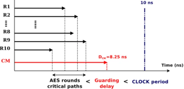
The countermeasure is based on a tunable guarding delay (Dcm)
that is longer than the most critical path of theAES(DpM ax) but
shorter than the clock period (Tclk). Eq. 2 and Fig. 2 illustrate this
constraint.
Tclk− Tsetup+ Tskew> Dclk2q+ Dcm> Dclk2q+ DpM ax (2)
ACONTROLsignal is used to tune the delay of the countermea-sure to fulfill the following constraints (see Fig. 3):
• The register (DFF) should sample a ’1’ when running in its nominal condition.
• TheDFF should sample a ’0’ when undergoing a physical attack.
• The countermeasure’s sensitivity (detection threshold) should be greater than theAES’s one (fault sensitivity).
The critical path of theAESdepends on both the input message and the key. To fix the value of the guarding delay, 10,000 [Plain-text, Key] couples have been tested. From our experiments, the guarding delay has been tuned in order to be longer (i.e 8.25 ns) than all the most critical path of theAESbut shorter than the clock period (i.e. 10 ns).
Figure 2: Guarding delay longer than theAESpath
As a result, when the circuit is under attack the alarm should be triggered before any fault being injected intoAEScalculations. Thus the countermeasure protects the circuit against timing con-straints violations. And the countermeasure sensitivity should not depend on the handled data. Thus, attacks such as Fault Sensi-tivity Analysis (FSA [16]) cannot be performed. The efficiency of this countermeasure against clock, power and electromagnetic
glitches has been studied in [17]. The countermeasure implemen-tation has to be close enough to theAES’s implementation to be efficient against electromagnetic injection.
For sake of clarity, only clock glitches have been used in this work but results could be extended to other kinds of disturbances injection means. As presented previously, the countermeasure has been designed to detect this kind of attack. Fig. 3 illustrates a glitched clock signal and the countermeasure detection principle. CLOCK is the nominal clock signal. CLOCK + Glitch is the clock signal when the circuit is undergoing a timing attack (in this case one of the clock periods is reduced). D − CLOCK + Glitch is the delayed clock of the countermeasure. The countermeasure’s register samples D−CLOCK +Glitch when CLOCK +Glitch rises. When the sampling result ALARM is ’0’ an alarm is trig-gered by another block and then the security policy is applied.
Figure 3: Delay-based countermeasure undergoing a clock glitch injection
As the guarding delay of the countermeasure is designed to be independent from the AES’s calculation, the detection threshold should not be data dependent. However, practical measurements showed that this assertion is unfortunately false. Fig. 4 reports the measured alarm detection rate as a function of the number of decrements of the clock period during theAESfirst round. Each decrement, or stress step by using the terminology introduced by [16], was equal to 35 ps. Alarm detection rates are given for 3 dif-ferent input messages, or plain texts, but the same secret key. It is clearly observable that the sensitivity of the countermeasure (i.e. its detection threshold) depends on the input message. This is a fault injection-based evidence of an information leakage between theAESimplementation and the countermeasure block. The aim of the next section is to confirm on experimental basis that this leakage is correlated with the sensitive data handle by theAES.
0 200 400 600 800 1000 40 45 50 55 60 # Alarm # Stress Steps M=120 M=139 M=169
Figure 4: Measure of the countermeasure’s sensitivity in round 1 for 3 different plain texts
3.
ELECTRICAL COUPLING BETWEEN
LOGICALLY INDEPENDENT BLOCKS
In this section the electrical coupling between logically indepen-dent blocks is described as an attack path to retrieve secret infor-mation. In this work, the two considered blocks were theAESand the countermeasure previously described. Theoretically, the coun-termeasure is data independent but measurements exposed in Fig. 4 tend to show the opposite.
3.1
Attack description
In fact, the attack procedure is very similar to theDPA. However, this attack measures a side effect of the power consumption instead of measuring it directly. This attack could also be considered as a
FSAtargeting the countermeasure detection threshold instead of the fault injection threshold.
The assumption we made is the following one:AEScalculations have an effect on the core voltage and the core voltage has an effect on the guarding delay of the countermeasure. These guarding de-lay variations can be monitored by measuring the alarm detection threshold. To measure the countermeasure sensitivity, the stress ap-plied to the circuit is gradually increased until an alarm is triggered. Then the same protocol than the one used for a classicalFSAorDPA
is used to correlate the detection threshold to the handled data.
3.2
Measurements of a side effect of the power
consumption
In this study, we considered the countermeasure detection thresh-old variations as a side effect of the power consumption. We mea-sured the alarm sensitivity by decreasing a chosen clock period step by step until the alarm was triggered. More generally the sensitiv-ity of the countermeasure could be monitored by increasing any kind of stress which has an effect on this countermeasure (under-powering, over-heating, electromagnetic pulse, etc.) [17].
3.3
Divide and conquer strategy
In this work we targeted the 1stround of the AESfor several practical reasons:
• The 16 bytes are independent until the first MIXCOLUMN. Every byte can be targeted one after each other.
• Only the first few steps of theAEShave to be simulated to calculate the selection function. (see Sec. 3.4.2)
3.4
Analysis
Notation: M is the input message of theAESand Miits ithbyte.
K0 is the secret key of theAESand K0iits ithbyte. SB is the
output of the first SUBBYTES block of theAESand SBi its ith
byte. In round 1, SBidepends only on Miand K0i.
In this specific case, the attack targeted only one byte after each other. If the uth byte is targeted then 0 ≤ Mi=u ≤ 255 and
Mi6=u= 0 (other bytes are chosen equal to zero). As a result for a
specific byte, there are only 256 different values for M . Moreover, in the following equations the byte index will be omitted.
3.4.1
Measurements
To perform the attack, the attacker first encrypts Nmaxtimes the
message M targeting round 1 with a stress S ∈ [0..60] (in this experiment the stress step is 35 ps). When S = 0 the circuit is running at its nominal value (i.e. 10 ns). For every encryption N ∈ [0..Nmax] of message M ∈ [0..255] with a stress S, the
at-tacker saves the alarm state A[N, M, S] (active or not). At the end of the experiment, an alarm state matrix A[0..255, 1..Nmax, 0..60]
is obtained. In other words the alarm state matrix give the alarm triggering state for a given stress S, applied during the the Nth encryption of the Mthplaintext.
The information of interest in this attack is the alarm detection rate for a given stress according to the considered message en-crypted. The alarm detection rate considering the Mth message for a given stress S is given by the equation Eq. 3 :
AlarmRate(M, S) = PNmax i=1 A[M, i, S] Nmax (3)
3.4.2
Prediction
In order to retrieve the correct key candidate, Kcorrect,
predic-tions have to be made according to a specific key candidate K. Then, these predictions have to be verified to score the key candi-date. As a result, predictions have to be related to an internal value which has an effect on the measured information (i.e. the alarm rate). The predicted value is called the selection function.
In this study, the selection function is the theoretical value of a given bit b of the targeted byte at the output of the first SUBBYTES
block, SB. For a specific byte, there are only 256 different values for the key candidate K. For every message M ∈ [0..255] and for every key candidate K ∈ [0..255], the selection function is denoted SB[M, K, b] ∈ [0, 1].
3.4.3
Correlation
Finally, the usual way to verify the assumption is to correlate the predictions to the measurements. In this study we assumed that a correlation existed between the selection function and the alarm detection rate
The Pearson’s correlation has been used to score every key didate. ρ(K, b, S) is the Pearson’s correlation index of a key can-didate K, of a given bit b, for a given stress S (Eq. 4).
ρ(K, b, S) = PearsCorr(SB[0..255, K, b], AlarmRate(0..255, S))
(4)
4.
EXPERIMENTAL RESULTS
In this section we focused on the first byte for the sake of clar-ity. As a result the attack presented in the following section was perfomed with a divide and conquer strategy. Only one byte of the input data was modified to recover the corresponding byte of the key. Results are very similar to those obtained targeting other bytes of the key. Final results are given in section 4.2.
4.1
"Information leakage" assumption
verifi-cation
A first step was to verify experimentally if the countermeasure sensitivity variations observed in Fig. 4 was linearly correlated to sensitive data. If the correlation exists then aDPA-like analysis could be successfully performed.
Every message was encrypted 1000 times for every different stress. Then the alarm detection rate (AlarmRate(M, S)) ob-tained for a specific message M with M ∈ [0..255] and with a specific stress S ∈ [0..60] was correlated to the selection function (SB[M, K, b]).
Fig. 5 represents the Pearson correlation score for all the differ-ent key candidates with SB[M, K, 1] used as a selection function. In this case the correct key candidate does not appear (for every key candidate and for every stress, the correlation absolute value is smaller than 0.3). Thus, this bit does not leak information about the secret key. -0.5 -0.4 -0.3 -0.2 -0.1 0 0.1 0.2 0.3 44 46 48 50 52 54 56 Pearson Correlation # Stress Steps Bit 1
Figure 5: PearsonCorr(SB[M, K, 1], AlarmRate(M,S)), no leak-age -0.5 -0.4 -0.3 -0.2 -0.1 0 0.1 0.2 0.3 44 46 48 50 52 54 56 Pearson Correlation # Stress Steps Bit 4
Figure 6: PearsonCorr(SB[M, K, 4], AlarmRate(M,S)), leakage
In Fig. 6 we turned our attention to the 4thbit of the
AES’ first byte, SB[M, K, 4] was used as a selection function. In this case, the correct key candidate appears (for one and only one key candi-date the correlation absolute value is greater than 0.3). As a result, the countermeasure sensitivity leaks enough information to retrieve the first byte of the secret key.
However in this case the attack was performed with 15,360,000 (256 plaintexts × 60 stress × 1000 encryptions) glitch injections (per byte). The following subsections report how to minimize the number of injections to perform the attack.
4.2
Targeting only one specific stress
The Pearson correlation is efficient at any stress within the non-deterministic zone of the countermeasure (S such as ∀M ∈ [0..255], 0 < AlarmRate(M, S) < 100) as illustrated in Fig. 6. As a result, targeting only one well-chosen stress could be enough to retrieve the secret key.
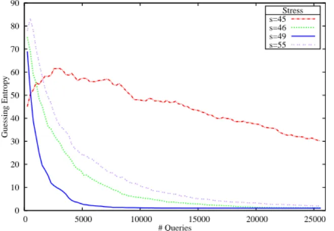
The effectiveness of different stresses were compared using the guessing entropy evaluation metric [18]. The guessing entropy GE(S) returns the average guessing position of the correct key Kcorrectafter a side-channel attack. Concerning passive side
chan-nel attacks such asDPAorCPA, the guessing entropy is usually plot-ted as a function of the total number of observations. Concerning this attack which is an active side channel attack, the guessing en-tropy is plotted as a function of the total number of glitch injections
(total number of messages × number of encryptions per message = 256 × Nmax).
Moreover, in this specific case, an alarm had to be triggered to retrieve the secret key. However, according to the attacker’s ability to avoid the alarm triggering effects (security strategies), this num-ber of triggered alarm could be more critical than the total numnum-ber of queries. 0 10 20 30 40 50 60 70 80 90 0 5000 10000 15000 20000 25000 Guessing Entropy # Queries Stress s=45 s=46 s=49 s=55
Figure 7: Guessing entropy function of the total number of injec-tions 0 10 20 30 40 50 60 70 80 90 0 1000 2000 3000 4000 5000 Guessing Entropy # Faults Stress s=46 s=49 s=55
Figure 8: Guessing entropy function of the average number of trig-gered alarms
In order to obtain an average guessing position of the correct key candidate Kcorrect, the attack was performed 200 times and results
are presented in Fig. 7 and Fig. 8.
In Fig. 7, the average guessing position when the attack was performed with a stress S (GE(S)) is plotted as a function of the total number of queries. In this figure, it appears that the guessing entropy tends faster to 1 when the stress applied lead to a medium range alarm rate (48 ≤ S ≤ 53). In our case, for a stress S = 49, around 7000 glitch injections were needed to retrieve a correct key byte. That represents around 1500 triggered alarms. As the number of triggered alarms could be a practical limitation for the attackers, Fig. 8 presents the same GE(S) as a function of the average num-ber of triggered alarms. In this figure, it appears that targeting the circuit with a low stress could be an interesting strategy to minimize the number of triggered alarms needed to retrieve the secret key. In
our case, targeting the circuit with a stress S = 49 minimize the total number of injections needed to retrieve the secret key (1500 alarms / 7000 injections) and a stress S = 46 minimize the total number of triggered alarms needed (800 alarms / 15000 injections). It is important to note that the number of triggered alarms could be a technical limitation of this attack. Indeed, a detection can lead to a key erasing. However, in the field of smart card for instance, key material could be kept in the EEPROM and erasing the infor-mation stored in the floating gate of a memory cell has a significant impact on the power consumption. This variation on the power con-sumption due to the injected glitch detection could be monitored by the attacker and then the chip could be reset and the sensitive infor-mation will be trapped [19]
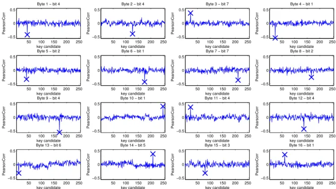
Fig. 9, illustrates the successful recovery of the whole bytes of the secret key with a stress S = 49 and Nmax = 1000 using the
most leaking bit as selection function SB[M, K, bleaking].
5.
CONCLUSION AND FURTHER WORKS
In this paper a new attack path has been introduced. This attack exploits electrical coupling between logically independent blocks to retrieve secret information. To illustrate this statement anAES
has been implemented on aFPGAboard. TheAESwas protected against fault injection with a delay-based countermeasure. This countermeasure and theAESimplementation were supposed to be two logically independent blocks (i.e. the countermeasure sensitiv-ity should not dependent on theAES’s calculations).
However, experiments point out the existence of a correlation between the attack detection threshold of the countermeasure and the data handled by theAES. This information leakage led us to find theAESkey. This result is especially worrying because it casts doubt on a kind of countermeasure [7] which was designed to pre-ventFSA. However, this new attack path involved a large number of alarm triggering, which may be a limitation for its practical effec-tiveness. Thus, we have completed this study by trying to minimize the number of these triggered alarms.
Next step of our work will be to perform similar attack on masked
AES’s implementation and discuss the results. Also, a better model to represent the power consumption and voltage drops propagation through the power supply grid could be built. With this model we could probably extract more information from these detection threshold variations such as voltage drops localization.
Acknowledgements
This work was supported in part by the European Commission through the ICT programme under contract FP7- ICT-2011-317930 HINT and was partially supported by a DGA-MRIS scholarship.
6.
REFERENCES
[1] P. C. Kocher, J. Jaffe, and B. Jun, “Differential Power Analysis,” in CRYPTO, 1999.
[2] W. Schindler, K. Lemke, and C. Paar, “A stochastic model for differential side channel cryptanalysis,” in CHES, 2005. [3] S. Chari, J. R. Rao, and P. Rohatgi, “Template attacks,” in
CHES, 2003.
[4] K. Tiri and I. Verbauwhede, “A logic level design methodology for a secure dpa resistant asic or fpga implementation,” in DATE, 2004.
[5] J.-S. Coron and L. Goubin, “On Boolean and arithmetic masking against differential power analysis,” in CHES, 2001.
50 100 150 200 250 −0.5 0 0.5 Byte 1 − bit 4 key candidate PearsonCorr 50 100 150 200 250 −0.5 0 0.5 Byte 2 − bit 4 key candidate PearsonCorr 50 100 150 200 250 −0.5 0 0.5 Byte 3 − bit 7 key candidate PearsonCorr 50 100 150 200 250 −0.5 0 0.5 Byte 4 − bit 1 key candidate PearsonCorr 50 100 150 200 250 −0.5 0 0.5 Byte 5 − bit 2 key candidate PearsonCorr 50 100 150 200 250 −0.5 0 0.5 Byte 6 − bit 1 key candidate PearsonCorr 50 100 150 200 250 −0.5 0 0.5 Byte 7 − bit 7 key candidate PearsonCorr 50 100 150 200 250 −0.5 0 0.5 Byte 8 − bit 2 key candidate PearsonCorr 50 100 150 200 250 −0.5 0 0.5 Byte 9 − bit 4 key candidate PearsonCorr 50 100 150 200 250 −0.5 0 0.5 Byte 10 − bit 1 key candidate PearsonCorr 50 100 150 200 250 −0.5 0 0.5 Byte 11 − bit 4 key candidate PearsonCorr 50 100 150 200 250 −0.5 0 0.5 Byte 12 − bit 4 key candidate PearsonCorr 50 100 150 200 250 −0.5 0 0.5 Byte 13 − bit 6 key candidate PearsonCorr 50 100 150 200 250 −0.5 0 0.5 Byte 14 − bit 5 key candidate PearsonCorr 50 100 150 200 250 −0.5 0 0.5 Byte 15 − bit 3 key candidate PearsonCorr 50 100 150 200 250 −0.5 0 0.5 Byte 16 − bit 1 key candidate PearsonCorr
Figure 9: Key recovering for every byte of the secret key with a stress S = 49 and Nmax = 1000 using the most leaking bit as selection
function
[6] M. Rivain, E. Prouff, and J. Doget, “Higher-order masking and shuffling for software implementations of block ciphers,” in CHES, 2009.
[7] S. Endo, Y. Li, N. Homma, K. Sakiyama, K. Ohta, and T. Aoki, “An Efficient Countermeasure against Fault Sensitivity Analysis Using Configurable Delay Blocks,” FDTC, 2012.
[8] A. Dehbaoui, J.-M. Dutertre, B. Robisson, and A. Tria, “Electromagnetic Transient Faults Injection on a Hardware and Software Implementation of AES,” in FDTC, 2012. [9] M. Joye, P. Manet, and J.-B. Rigaud, “Strengthening
hardware aes implementations against fault attacks,” IET Information Security, 2007.
[10] L. Shang, A. S. Kaviani, and K. Bathala, “Dynamic power consumption in virtex-ii fpga family,” in FPGA, 2002. [11] K. M. Zick, M. Srivastav, W. Zhang, and M. French,
“Sensing nanosecond-scale voltage attacks and natural transients in fpgas,” in FPGA, 2013.
[12] J.-M. Schmidt, T. Plos, M. Kirschbaum, M. Hutter, M. Medwed, and C. Herbst, “Side-channel leakage across borders,” in CARDIS, 2010.
[13] S. Endo, T. Sugawara, N. Homma, T. Aoki, and A. Satoh, “An on-chip glitchy-clock generator for testing fault injection attacks,” J. Cryptographic Engineering, 2011. [14] L. Zussa, J.-M. Dutertre, J. Cl´edi`ere, and A. Tria, “From
physical stresses to timing constraints violation,” IOLTS, 2013.
[15] N. Selmane, S. Bhasin, S. Guilley, and J.-L. Danger, “Security evaluation of application-specific integrated circuits and field programmable gate arrays against setup time violation attacks,” IET Information Security, 2011. [16] Y. Li, K. Sakiyama, S. Gomisawa, T. Fukunaga, J. Takahashi,
and K. Ohta, “Fault sensitivity analysis,” in CHES, 2010.
[17] L. Zussa, A. Dehbaoui, K. Tobich, J.-M. Dutertre, P. Maurine, L. Guillaume-Sage, J. Clediere, and A. Tria, “Efficiency of a glitch detector against electromagnetic fault injection,” in DATE, 2014.
[18] F.-X. Standaert, T. G. Malkin, and M. Yung, “A unified framework for the analysis of side-channel key recovery attacks,” in EUROCRYPT, 2009.
[19] R. Anderson and M. Kuhn, “Tamper resistance-a cautionary note,” in Proceedings of the second Usenix workshop on electronic commerce, 1996.

![Fig. 5 represents the Pearson correlation score for all the differ- differ-ent key candidates with SB[M, K, 1] used as a selection function.](https://thumb-eu.123doks.com/thumbv2/123doknet/12846954.367608/5.892.490.817.80.307/represents-pearson-correlation-differ-differ-candidates-selection-function.webp)