HAL Id: cea-02500834
https://hal-cea.archives-ouvertes.fr/cea-02500834
Submitted on 6 Mar 2020HAL is a multi-disciplinary open access archive for the deposit and dissemination of sci-entific research documents, whether they are pub-lished or not. The documents may come from teaching and research institutions in France or abroad, or from public or private research centers.
L’archive ouverte pluridisciplinaire HAL, est destinée au dépôt et à la diffusion de documents scientifiques de niveau recherche, publiés ou non, émanant des établissements d’enseignement et de recherche français ou étrangers, des laboratoires publics ou privés.
Simulation of the static mechanical behaviour of a
pressuried water reactor fuel assembly
F. Yao, C. Strub, P. Le Tallec
To cite this version:
F. Yao, C. Strub, P. Le Tallec. Simulation of the static mechanical behaviour of a pressuried water reactor fuel assembly. SMIRT 23 - 23th International Conference on Structural Mechanics in Reactor Technology, Aug 2015, Manchester, United Kingdom. �cea-02500834�
SIMULATION OF THE STATIC MECHANICAL BEHAVIOUR OF A
PRESSURIED WATER REACTOR FUEL ASSEMBLY
Fang Yao1, Claude Strub2, Patrick Le Tallec3
1 P.H.D Student, CEA, DEN, DM2S, SEMT, CEA Saclay, F-91191 Gif-sur-Yvette, France 2 Researcher, CEA, DEN, DM2S, SEMT, CEA Saclay, F-91191 Gif-sur-Yvette, France 3 Director of Solid Mechanics Laboratory, Ecole Polytechnique, 91120 Palaiseau, France
ABSTRACT
The paper presents the mathematical modelling and computer simulation of static mechanical response of a PWR fuel assembly, with the help of the finite element code “CAST3M” [6] developed by CEA. In PWR core analysis, the fuel assemblies present non-linear behaviour, which can be explained by the variations of stiffness due to the contact and the slipping between fuel rods and spacer grids as well as to the loss of contact of the rods. In the first part of this paper, a rod-to-grid contact model, based on the Coulomb law and constituted of non-linear springs and hinges, is developed to simulate the holding system of fuel rods inside the grid cells. The results of simulation showed a quite good agreement with the numerical reference model. The second part aims at applying the domain decomposition methods to the modelling of the fuel assembly with the proposed contact model. Due to geometric complexity of the fuel assemblies, the approximation by finite element method leads to a large number of unknowns. The resolution of this system would be prohibitively expensive with the available computation power. By using the domain decomposition methods we are able to reduce a significant amount of computational time and relieve the memory requirement from the advantage of parallel computing.
INTRODUCTION
The nuclear fuel assembly is one of the major components of a pressurized water reactor (PWR). During the service in the core, it has to withstand to irradiation, high temperatures, mechanical loads and corrosion environment with minimal changes in stiffness characteristics and geometry. For the designer and maintenance purposes, the numerical methods are generally applied to study their behaviour under different operation conditions, both normal and accidental. The first aim of this paper is to present a rod-to-grid contact model which illustrates sufficient local phenomena to be predictive but remains simple enough to be used in a whole fuel assembly simulation. On the second part, the application of the domain decomposition methods to the modelling of fuel assembly is realised, which shows the potential to reduce the computational time and relieve the memory requirement from the advantage of parallel computing.
PWR FUEL ASSEMBLY DESCRIPTION
A nuclear fuel assembly of PWR is composed of two main parts. One portion consists of the fuel rods containing fuel pellets. They are cylindrical metallic tubes about 4 meters long and form an arrangement of 14x14 to17x17. The other part contains the support structure of the fuel rods, including 10 to 11 spacer grids, 24 guide tubes as well as upper and lower tie plates. The spacer grids are designed to hold a minimum gap between fuel rods to allow the cooler flow and to contribute to the lateral stiffness of the assembly. The fuel rods are maintained in the spacer grids by springs and dimples.
EXPERIMENTAL BEHAVIOUR
To study the mechanical behaviour of the PWR fuel assembly, many tests have been performed on the single assembly. During these tests, the boundary conditions imposed at both ends of the fuel
23rd Conference on Structural Mechanics in Reactor Technology Manchester, United Kingdom - August 10-14, 2015 Division III
assembly are similar to those existing in the actual core and a load is applied to the middle grid. The deflection at middle grid is measured and is plotted versus load level. The results show that the assembly stiffness decreases when loading becomes higher. The global behaviour of the PWR fuel assembly is nonlinear and shows hysteresis. This phenomenon comes principally from the interactions between fuel rods and spacer grids, like impact, sliding, or combines impact and sliding motions, including friction.
NON LINEAR LINK MODEL BETWEEN GRIDS AND FUEL RODS
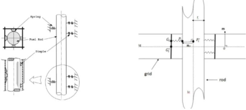
Three-dimensional beam-to-shell model is considered in this study, with the beams representing the fuel rods and the shells representing the mean plane of the grids. For each cell of the spacer grid, every spring or dimple is assumed to be a single point ( , 1, … , . N defines the number of springs and dimples in one cell), fixed on the wall of the cell. This is illustrated in Fig.1. The point 1, … , . refers to the normal projection of the support point on the tube’s surface. The projection of the points and respectively on the mid-surface of the shell and the axis of the beam are noted ∗ and ∗, characterized by the distances and (radius of the beam). The movements of and are conditioned by the Mindlin-Reissner theory for thick plates as well as the Euler-Bernoulli beam theory. In the current work an attempt is made to propose a model which describes the interactions between the rod and N supports in one cell.
Figure 1. Fuel rod support model
Constitutive laws for contact and friction interactions
In order to formulate contact conditions, a local coordinate system is associated to each support point . It consists of a normal direction from to , denoted , an axial direction of the beam , as well as the third direction defined by . The normal and tangential distances between and , defined as the and are expressed as follows :
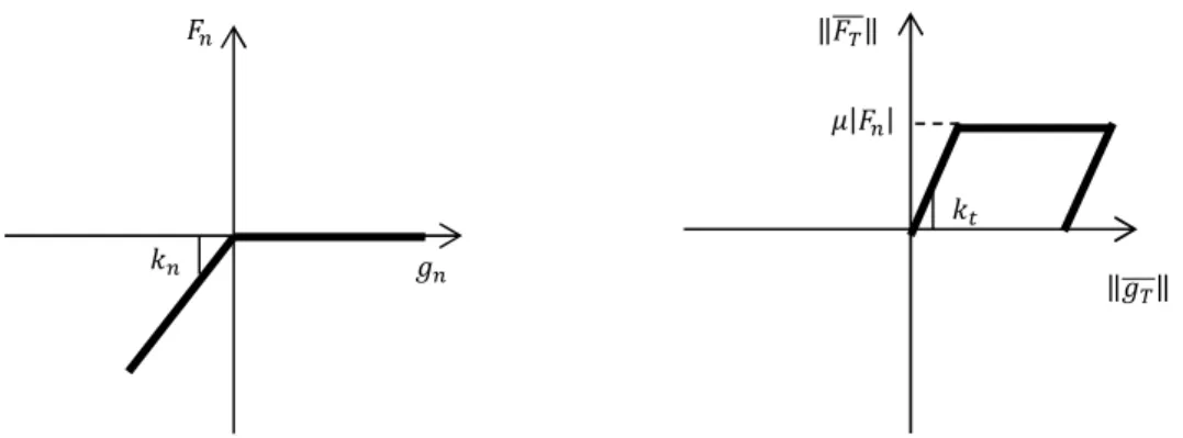
, 0. (1) (2) A constitutive law for normal contact is considered in order to link normal reactions ! to the
measured at contact points. We use the form of penalty law, which is regularized by a linear part for very small penetrations with stiffness " in order to stabilize the contact algorithm (see Fig. 2). As for the friction, we use a Coulomb’s law including a small reversible elastic displacement with stiffness " before sliding occurs.
Where ! is the friction force and % is the coefficient of friction.
Figure 2. Law of normal (left) and tangential (right) behavior.
Finite element implementation
Normal and tangential forces at contact points have been expressed as functions of the displacements of the pairs of contact particles and . With the kinematical model employed, the displacement
at particle on shell can be written as:
∗ + &̅ ∗ . (4) Where ∗ and &̅ ∗ are respectively the translation and the rotations of the mid-surface of the shell at particle ∗. These two kinematical vector fields are approximated using a finite element interpolation. If the shell element has 8 nodes, the interpolated kinematical vectors can be expressed as follows:
∗ = ∑+, ,-Ψ* ∗ .+, (5) &̅ ∗ = ∑ Ψ
* ∗
+, ,- Β+. (6) Where Ψ+ is the shape functions associated to the i-th node of the element, and .+, Β+ are the kinematical vectors defined at this node. Finally, the interpolated displacement of the particle is written as:
= ∑+, ,-Ψ* ∗ .++ ∑+, ,-Ψ* ∗ Β+. (7) Supposing that the portion of the rod which would interact with the grid contains M 2-nodes beam elements, the displacement of the particle can be obtained by the same way:
= ∑2, ,34 Φ1 ∗ .2+ ∑2, ,34 Φ1 ∗ Β2. (8) With Φ2 the shape functions and the .2, Β2 the kinematical vectors associated to the j-th node of the beam element which interacts with the grid.
Global algorithm
For each loading increment, one loop is dedicated to the fixed point algorithm in order to determine contact points, contact status and the associated local coordinate system associated. When these quantities are fixed, a Newton Raphson algorithm is used to solve the nonlinear mechanical problem.
Numerical solutions " ! ‖!5‖ ‖ 5‖ " %|! |
23rd Conference on Structural Mechanics in Reactor Technology Manchester, United Kingdom - August 10-14, 2015 Division III
The application to the static analysis on a spacer grid with 264 rods and 25 guide tubes has been performed. The rods are arranged in 17 rows and maintained in each cell of the grid by 2 springs and 4 dimples. There is one rod which is much longer than the others (see Fig.3). The guide tubes are welded to the spacer grid and clamped at both ends. We impose a bending force to the long rod.
Figure 3. 17X17 spacer grid finite element model
The simulation has been realised with the help of the finite element code “CAST3M” developed by CEA. Each cell of the grid is represented by an 8-node shell element, the rods are described with 2-node beam elements and the interactions in each cell are simulated by the non-linear link model as described before.
In Fig.4, the computational solution is plotted on a graph which gives the bending moment versus rotation of the long rod. It is compared with the numerical results of a reference model which considers each point of contact as a link element JOI1, available in the code CAST3M. The reference model has been validated by experimental experience. It appears that our model is able to predict the behaviour of the structure in the linear and non-linear region. The transition phases correspond to the stages where rods begin to loose contact with dimples or slide inside the grid cells.
Figure 4. Moment vs. rotation of the long rod
APPLYING THE DOMAIN DECOMPOSITION METHODS TO THE MODELLING OF THE FUEL ASSEMBLY
Introduction
Due to the geometric complexity of PWR fuel assemblies, the approximation by the finite element method leads to a large nonlinear system. This nonlinear problem is generally characterized by large computational times. So the substructuring methods which are efficient on parallel computer with
A
B
C
D
adapted preconditioner are appreciated. The aim of the work is to present application of the Balancing Domain Decomposition (BDD) method to solve this algebraic system. The BDD method was developed from the Neumann-Neumann preconditioner of De Roeck and Le Tallec [1] by Mandel [2], who has modified the algorithm by adding a coarse problem with few unknowns per subdomain. Solving the coarse problem in each iteration coordinates the solution between the subdomains and prevents any slow-down when increasing the number of subdomains.
BDD method applied to the solution of linear systems
We first recall briefly the algorithm to solve the linear problems 7. = ! following [2]. 7 represents the global stiffness matrix, . indicates the global degrees of freedom, and ! implies the external forces. The local degrees of freedom of subdomain Ω is . and the corresponding stiffness matrix is noted 7 . Let denote the mapping matrix with entries 0 or 1, then we have . = .. Write local stiffness matrix:
7 = 9:<5; :̅ =< . (9) Where :̅ corresponds to degrees of freedom on the interface of subdomain n. By eliminating the remaining degrees of freedom, we obtain the reduced system:
>.?= !? (10) Where .? are the interface degrees of freedom. The matrix S is the Schur complement:
> = ∑ > , > = : − < :; @ < . (11) If we write ! = !; ! 5, with ! corresponding to the force at the interface of each subdomain, and !; corresponding to the force inside each subdomain then:
!?= ∑ A! − < :; @ !; B (12) The system (10) is solved by a preconditioned conjugate gradient algorithm which has a two level Neumann-Neumann preconditioner. To construct the preconditioner, we have to define the coarse space:
C = DE ∈ G ∶ E = ∑ I . , . ∈ JK L M . (13) With, ∑ I = J , 7N > ⊂ JK L+, and Gthe space of vectors of degrees of freedom on the interface Γ. Then the preconditioner Q@ can be written as:
Q@ >.? = 5>.?+ J − ∑ > J − 5>.?. (14) Where P indicates the projection of le space .? into the coarse space H.
Adaptation of the BDD method in the case of frictional contact problems
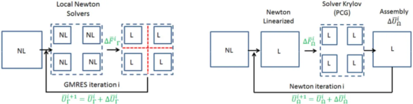
As we have seen in the previous section, the mechanical behaviour of a PWR fuel assembly is highly nonlinear due to the interaction between the grids and the rods. The solution of this static problem generates at each load increment or time step a nonlinear system solved by the classical Newton’s method. The BDD method can be applied as preconditioners in two ways: the BDD nonlinear inside [3], and the BDD nonlinear outside [4], described in Fig. 5, where NL is nonlinear system and L for
23rd Conference on Structural Mechanics in Reactor Technology Manchester, United Kingdom - August 10-14, 2015 Division III
the linearized system. ∆!?+ and ∆!S+ correspond respectively to the residual force field at the interface Γ and inside subdomain Ω.
Application to friction contact problems
In this section, we show the application of these two methods to determine the mechanical behaviour of a fuel assembly part. The application relates to the same case as described in previous section ‘Numerical solutions’. The structure is decomposed in 9 subdomains (see Fig.6). From this numerical experiment, we analyse the convergence behaviour of the two different methods. The results show that for the BDD nonlinear outside method, the number of iterations of the interface solver, Preconditioned conjugate gradient (PCG), is stable for each Newton iteration (see Table.1). However, the BDD nonlinear inside presents the disadvantage for the system concerned. This might be due to the fact that the friction contacts can appear everywhere in the structure, which makes interface solver, Generalized minimal residual method (GMRES) with the two level Neumann-Neumann preconditioner, display the convergence difficulties.
Figure 5. Scheme of the BDD nonlinear inside method (left) and outside method (right) for a time step
Figure 6. Substructuration of the spacer grid in 9 subdomains.
Table 1: Results of BDD nonlinear inside (left) and BDD nonlinear outside(right).
Time step /Moment(Nm)
Iteration GMRES
(for each Newton method)
Time step /Moment(Nm)
Iteration GMRES
(for each Newton method)
A 20 A 13
subdomains
domain decomposition interface
B 30 B 13
C - C 13
D - D 13
E - E 13
CONCLUSION
A nonlinear rod-to-grid contact model has been proposed, in order to simulate the static mechanical behaviour of the PWR fuel assembly. This model represents the progressive movement between rods inside grids taking into account friction. The comparison of the static behaviour of this model with a numerical reference one performed on a fuel assembly part shows a quite good agreement. The application of the balanced decomposition domain methods to fuel assembly simulation illustrates a possibility to reduce the computational time and relieve the memory requirement by realizing parallel computing.
REFERENCES
[1] Y-H. DE ROECK, P. LE TALLEC (1991). “Analysis and test of a local domain decomposition preconditioner” Fourth International Symposium on Domain Decomposition Methods for
Partial Differential Equations, SIAM, Philadelphia, PA.
[2] J.Mandel. (1993). Balancing domain decomposition, Comm. In Numerical Methods in Engrg.9, 233-241.
[3] Ph. CRESTA, O.ALLIX, Ch. REY, S. GUINARD (2007). “Nonlinear localization strategies for domain decomposition methods: application to post-buckling analyses” Comput. Methods. Appl.
Mech. Engrg., Vol. 196, Issue 8, 1436-1446.
[4] Y-H. DE ROECK, P. LE TALLEC, M. VIDRASCU. (1992). “A domain-decomposed solver for nonlinear elasticity” Comput. Methods. Appl. Mech. Engrg., Vol. 99, 187-207.
[5]International Conference of Building Officials. (1988). Uniform Building Code. Whittier, California, USA.