%0$503"5%&-6/*7&34*5²%&506-064&
Institut National Polytechnique de Toulouse (INP Toulouse)
Mécanique, Energétique, Génie civil et Procédés (MEGeP)
"Optimisation of microstructure and fatigue properties of Inconel 718 for extrusion die applications"
mardi 18 octobre 2011
Fabio TAINA
Génie Mécanique, Mécanique des Matériaux
André PINEAU - Professeur - Centre des Matériaux - Ecole des Mines de Paris Mario ROSSO - Professeur - DISMIC- Politecnico di Torino
Philippe LOURS- Professeur- ICA Albi- Directeur de thèse Denis DELAGNES- Maître Assistant- ICA Albi- Co-Directeur de thèse
Institut Clément Ader (ICA)-Albi- Ecole des Mines d'Albi
Remerciements
Apres trois années de travail intensif, mais passionnant, au sein de l’Institut Clément Ader, j’ai enfin l’occasion de remercier toutes les personnes qui ont contribué à la bonne réalisation de ce travail dans une ambiance conviviale.
Je tiens en premier lieu à remercier Philippe Lours, qui m’a encadré pendant la durée de cette thèse.
Tu as su me donner suffisamment d’autonomie tout en restant présent dans les moments où j’avais besoin de tes indications sur les directions de recherche. Je te remercie également de m’avoir accueilli dans ta famille la veille de ma soutenance de thèse, ce qui a mis un peu de chaleur dans un moment aussi important.
Mes remerciements vont également à Denis Delagnes, dont je tiens à féliciter l’aboutissement de son HDR. Tu as contribué à ma formation en répondant avec patience à mes questions de jeune naïf sur les problématiques de fatigue oligocyclique. Je garderais aussi en mémoire les nombreuses discussions qu’on a pu avoir le mardi, à midi, dans les vestiaires du gymnase.
Je suis très reconnaissant au Professeur André Pineau d’avoir accepté de relire et de critiquer mes travaux de thèse. Ce fut un honneur pour moi de discuter avec vous sur ce matériau intéressant mais complexe dont vous avez contribué, de manière essentielle, au développent de la connaissance.
Je ne pourrais jamais oublier notre première rencontre pendant laquelle vous avez su non seulement répondre à mes question mais aussi à celles des « dix-huit personnes » qui vous ont sollicité pendant cette entrevue.
Je réserve un remerciement chaleureux au Professeur Mario Rosso pour sa grande disponibilité lors du cursus au Politecnico de Turin et en suite pour la relecture de la thèse. J’ai sincèrement apprécié de travailler avec toi et je te suis reconnaissant pour le temps que tu m’as consacré et toutes les opportunités que tu m’as données au cours de ces années.
Mes remerciements s’adressent aussi au Professeur Eric Andrieu qui m’a fait l’honneur de présider mon jury de thèse. De même, je remercie Jean-Luc Lanfranchini, directeur du centre R&D au sein de Technal, pour avoir mobilisé un peu de son temps et de ses compétences pour participer à la soutenance.
J’adresse sincèrement mes remerciements à Marco Pasqualon, qui a été mon encadrant industriel au sein d’Hydro Aluminum. Votre investissement et votre disponibilité m’a permis d’évoluer dans les meilleures conditions : les nombreuses réflexions et discussions que nous avons échangés par mail et téléphone ont été les moteurs de ce travail.
J’ai eu la chance de travailler pendant la dernière période de ma thèse avec Vincent Velay, enseignant chercheur au sein de l’ICA, qui a encadré et orienté mes travaux de recherche portant sur la modélisation numérique et le comportement mécanique des matériaux. Son humilité et ses remarques constructives m’ont permis d’aborder un sujet complexe mais riche d’intérêt industriel et scientifique.
Une thèse focalisée sur la fatigue mécanique ne peut pas être réalisée sans la contribution d’une équipe technique à la hauteur des exigences. C’est pour cette raison que je tiens tout d’abord à remercier Thomas Papaïx d’avoir assisté à la rupture de 125 éprouvettes, de nombreux nettoyages de spires, du remplacement de 3 paires de tiges d’extensomètre (dont une cassée par ma maladresse) ainsi que pour un samedi matin passé devant la « Shenck », qui semblait complètement
Mes remerciements vont également à Monsieur Serge Tovar pour sa maitrise du MEB et celle des attaques chimiques. Si aujourd’hui, je parle aussi bien français, c’est un peu grâce à toi, Serge.
Merci encore pour les nombreux surnoms que t’as su adapter à ma personnalité ; j’en cite quelques un pour qu’ils ne soient pas oubliés : « Felice !!! », « Pizzaiolo », « Ma che » !!!, « Spaghetti »,
« Rital », etc... Comme promis, je t’enverrai par courriel la fameuse recette de la « Pizza aux trois fromages ».
Que ce soit sur le site industriel d’Hydro ou au sein du laboratoire ICA, j’ai eu la chance tout au long de ces trois années d’être entouré par des assistantes administratives extrêmement efficaces et qui m’ont rendu la vie plus facile. Un grand merci donc à Josiane, Cathy et Esther pour votre aide et soutien.
Merci à toutes les personnes du laboratoire qui ont répondu présentes à chaque fois que je les sollicitais : Sabine pour les analyses d’images, Pascal pour l’ATD et la DRX, Vanessa pour les belles images au TEM, Didier pour les trois jours de corrélation d’images (passés devant la machine avec de la bonne musique), Florian pour le support informatique (et les discussions autour de l’Italie
« Ti faccio cappuccino !!! » et le centre de documentation (Nelly, Hong et Dolores) pour le soutien constant. Enfin merci à toutes les personnes que je n’ai pas citées ici et qui se reconnaîtront dans ces quelques lignes.
Cette aventure aurait sans doute été moins agréable sans la présence des amis doctorants qui m’ont supporté pendant mon parcours. Je souhaite remercier tous les amis du bureau 1M07 qui ont toujours contribués à créer une ambiance de travail joviale même pendant les moments les plus tendus et l’ensemble des thésards avec lesquels j’ai partagé l’organisation de nombreuses initiatives liées à l’Association des doctorants (ACTA). Parmi eux, certains m’ont fait don de leur amitié. Tous ont contribué à me faire grandir tant au niveau professionnel que personnel. Bonne continuation à vous tous! Un grand merci à Cédric grâce à qui j’ai pu connaître les terres inconnus des dissolutions électrolytiques. Même en étant aussi différents en carrure qu’en caractère, on a mis en place une belle collaboration, basée sur une vraie amitié, dont je te serai toujours reconnaissant. Et dans cet esprit de convivialité, je ne pourrai jamais oublier les amis du Volley, l’équipe des « Caribous », qui a constitué ma deuxième famille sur Albi. Je me souviendrai longtemps de ces moments inoubliables, toujours avec le sourire sur les lèvres et la joie dans le cœur. Je vous remercie de m’avoir accueilli dans votre équipe dont je garderai toujours le souvenir de ce championnat cuvée 2011 en « Chantant dans le COSEC ». Un remerciement en particulier pour Thierry, pour son être humble et pour son faire « impeccable !!! » et pour JB, ou mieux « Monsieur Caribou » pour son dynamisme et pour son « clin d’œil ».
Je suis en outre tout spécialement reconnaissant à Giorgio avec lequel je partage une amitié qui dure depuis longtemps, malgré la distance qui nous sépare (1000 km). Ton soutien au quotidien et ta capacité à me faire oublier les problèmes professionnels ont été indispensables pour moi.
J’adresse toute ma gratitude à mes parents, pour leur présence et leur exemple. Pour leur capacité à accepter et supporter mes choix et mon éloignement et pour m’avoir aidé dans les différentes étapes de ma vie étudiante et le début de la vie professionnelle.
Enfin, les remerciements les plus sincères c’est pour Claire, qui représente avec son amour un repère constant et solide. Merci d’avoir accepté de partager ce studio de 16 m2 et pour tous les week-ends et les nuits d’étude et de rédaction, ton sourire et ta joie de vivre ont effacé la fatigue et donné de la couleur à ces trois années de vie albigeoise. Je suis certain que mes encadrants ne se vexeront pas si j’écris que tu as été la découverte la plus importante de mes recherches. Bon courage pour ta nouvelle vie professionnelle, en espérant que nous pourrons réaliser, au plus tôt, nos rêves.
6
I Introduction
The Aluminium extrusion is a high temperature process used to produce semi-finished products in the form of bar, strip and solid sections as well as hollow sections. Extrusion processing includes a plastic deformation in which a billet, typically cylindrical, is forced by a stem to pass through a die with a cross section generating the shape of the extruded piece.
Due to the severe processing conditions and complex mechanical loading, the die is considered as the most critical element of the extrusion equipment.
The thermo-mechanical loading and the continuous contact between the tool and the aluminium enhance the risks of wear and fatigue failures. The alternation of tensile and compressive stresses, acting on specific zones of the die, such as sharp corners and/or section changes, represents one of the most common causes of the fatigue failure. A second significant failure is associated to friction damage on the bearing surfaces which is defined as a progressive wear of the die material.
Different researches have been performed with the objective to increase die life and reduce the connected ratio die cost/kg extruded. Improving die stability can also generate significant profit through process reliability and productivity increase as well as product quality stabilization (surface, dimensions).
A so-called “Modular” extrusion die was designed by Hydro Aluminium and prototypes were tested. For this innovative die, the part subject to strong thermo-mechanical (First module) loading was made with a Nickel-based Superalloy (Ni-SA) whereas in the bearing zone (Second Module), the insert was manufactured with a wear resistant material (such as high speed tool steel, hot working steel or precipitation hardened steel) optimised by the application of a specific coating. In particular, Inconel 718 was selected as the appropriate candidate material for the bulk structure, able to combine excellent tensile, fatigue, creep and rupture strength in the range of temperature where the die operate (almost 550° C).
The aim of this PhD work is to contribute to the development of die materials for aluminium extrusion, for a continuous improvement of the productive capabilities of Hydro Aluminium to achieve a leadership in industrial products within a global market.
Even tough the “Modular Extrusion Technology” has recently shown important benefits and good results in extrusion practice, this application is still at an early stage of its potential exploitation. The originality of the present work stands on the development of an optimized Inconel 718 alloy, with thermo-mechanical and microstructural tailored properties for a specific application, that is bulk material for extrusion die.
From this point of view, two possible research strategies can be explored:
- The investigation of the impact of the extrusion process such as extrusion speed,
Introduction
2
tests giving information on the various damage mechanisms occurring in the die.
- The optimization of the Inconel 718 properties to improve its strength under extrusion loading. This second objective could be achieved by modifying the Material Intrinsic Parameters such as grain size, precipitates morphology through thermo-mechanical treatments in order to adapt the material to the specific conditions imposed by the extrusion process.
The manuscript is organized in five sections.
Chapter I discuss the fundamentals of the extrusion process, focusing on the die technology and presenting in detail the concept of “Modular Extrusion die”.
A literature review about Inconel 718 is reported in Chapter II to give a synthetic description of the wide variety of researches that have been previously carried out on this material. This preliminary chapter is considered as a pertinent support for the interpretation of the experimental results that will be reported in the second part of the manuscript.
Chapter III includes a detailed description of the research strategies adopted for the metallurgical optimization of the alloy. A presentation of the different experimental methods used for the metallurgical and mechanical characterisation of the alloy is reported.
The fatigue behaviour of Inconel 718 is analysed in Chapter IV under various LCF conditions. Different examples of tests are carried out in order to define a cyclic model prone to evaluate the stress-strain state in an extrusion die. In addition, a series of strain-controlled low cycle fatigue tests is conducted to investigate the impact of various parameters on the behaviour of the material. Namely, focus is placed on the influence of the extrinsic parameters such as the cycle frequency, the strain rate, the holding time under load and the stress relaxation. A fractographic method, based on microscopical investigations, is proposed in order to predict the crack growth rate of prevalent cracks under LCF conditions.
Alternative heat treatments, in addition to the standard procedure, are proposed in Chapter V where their mechanical properties have been assessed by tensile tests. Each modified thermal treatment is defined by a series of parameters (time, temperature, cooling rates), whose choice is related to a detailed study of the correlation between microstructure and mechanical properties. This investigation is based on the understanding and modelling of the various steps of the heat treatment process, taking into account the evolution of the so-called material-intrinsic parameters.
Finally, some concluding remarks are reported in order to resume the main results of the research focused on the understanding and the improvement of the mechanical behaviour of the tool bulk material (Inconel 718). Specific suggestions and additional outlooks, from a scientific and industrial point of view, are discussed in order to further increase die life, process stability and later on press productivity.
Index
I Introduction ... 1
Index ... 3
Chapter I: State of the art and scope of the research work ... 11
II Fundamentals of Extrusion ... 11
II.1 Introduction ... 11
II.2 The Hot Extrusion Technology ... 11
II.3 Hot work steels for extrusion dies: state of the art... 15
II.4 The extrusion cycle and die loading... 17
II.5 The failure mechanisms of the aluminium extrusion dies ... 20
III The modular extrusion die: a new concept of extrusion tool... 20
III.1 Investigation of a real case of tool fracture ... 22
IV Outlooks and Objectives of the project ... 24
V References ... 26
Chapter II: Microstructure and mechanical properties of Inconel 718 ... 31
VI Introduction ... 31
VII The nickel based superalloys... 31
VIII Metallurgy and composition of Inconel 718 ... 32
IX Secondary phases and strengthening effects ... 35
IX.1 Effect of alloying elements on the precipitation behaviour. ... 38
IX.2 The precipitation behaviour in Inconel 718 ... 40
X Deformation mechanisms in Inconel 718 ... 42
X.1 Tensile behaviour ... 46
X.2 Cyclic Deformation behaviour of Inconel 718... 47
XI Fatigue damage... 52
XI.1 Crack initiation ... 52
XI.2 Crack propagation ... 55
XI.3 Environmental effects ... 58
Index
4
mechanical behaviour ... 65
XII.1 Delta phase impact on the mechanical behaviour ... 65
XII.2 The Dynamic Strain Aging (DSA) ... 67
XIII Conclusions ... 71
XIV References ... 72
Chapter III: Strategy for Inconel 718 microstructure design and experimental methodology ... 81
I Introduction ... 81
II Microstructure of standard Inconel 718... 82
II.1 Composition ... 82
II.2 Thermal treatment ... 82
II.3 Microstructure ... 83
II.4 Tensile strength ... 85
III Alternative Inconel 718 grades ... 86
III.1 Intra-specification heat treatment design ... 88
III.2 Extra-specification heat treatment design ... 91
III.3 Thermo-mechanical treatment ... 92
IV Thermo-mechanical investigation ... 93
IV.1 Low cycle fatigue test method ... 93
IV.1.A Induction heating ... 94
IV.1.B Strain measurements ... 94
IV.1.C Specimens ... 94
IV.1.D LCF test procedure... 95
IV.2 Low cycle fatigue test conditions... 96
IV.3 Tensile test conditions ... 96
V Microstructural investigation ... 96
V.1 Hardness measurements ... 97
V.2 Optical Microscopy ... 97
V.3 Scanning Electrons Microscopy (SEM)... 97
V.3.A Metallographic samples preparation ... 98
V.4 Transmission Electron Microscopy (TEM) ... 98
V.5 Image Analysis ... 99
V.6 Synchrotron X-ray diffraction... 100
V.7 Thermo-analytical techniques ... 100
V.7.A Differential Thermal Analysis (DTA) ... 101
V.7.B Thermal Expansion measurements ... 101
V.8 Thermal treatments method... 102
V.9 Isolation and determination of the lattice misfit of intermetallic phases 102
V.9.A Precipitates extraction... 103V.9.B X-ray diffraction ... 103
V.9.C Crystallographic lattice parameters evaluation... 103
VI Conclusions ... 105
VII References ... 106
Chapter IV - Fatigue performances of standard Inconel 718: the influence of material-extrinsic parameters ... 109
I Introduction ... 109
II Cyclic behaviour of Inconel 718... 110
II.1 Experimental procedure for behaviour model identification ... 111
II.2 Identification and validation of a cyclic elasto-plastic model... 115
II.3 The application of the Dynamic Modelling to an industrial case: the Inconel 718 base tube extrusion die. ... 119
II.3.A Case description and model integration... 119
II.3.B Dynamic model validation... 123
II.3.B.1 Experimental approach – FE benchmark with static model ... 123
II.4 Partial Conclusions... 124
III Fatigue life of Inconel 718 under isothermal LCF conditions ... 126
III.1 Introduction ... 126
III.2 Fatigue life assessment... 126
III.3 Cyclic stress-strain response ... 130
III.4 Representation of extrusion loading by LCF tests ... 134
III.4.A Effects of holding time on the fatigue behaviour ... 138
III.4.B Strain rate effects on fatigue behaviour ... 139
III.4.B.1 Initiation of fatigue cracks ... 144
III.4.B.2 Propagation of fatigue cracks... 144
IV Quantitative analysis of fatigue crack growth by fractographic
investigations ... 145
Index
6
IV.4 Fractographic reconstitution methodology ... 148
IV.5 Crack growth rate assessment ... 154
IV.5.A Relationship between Low Cycle Fatigue properties and crack growth rates 155 IV.5.B Comparison with experimental results ... 161
V Conclusion... 163
VI References ... 167
Chapter V – Relationships between tailored microstructure and fatigue life .. 173
I Introduction ... 173
I Structural characterization of heat treated Inconel 718 ... 173
I.1 Cooling rate effects ... 173
I.2 Structural evolution of Inconel 718 during heating process ... 176
I.3 Delta phase and grain structure evolution ... 177
I.4 Aging effects on the structural evolution ... 185
II Fatigue behaviour of Inconel 718 alternative grades... 189
II.1 Intra-specification thermal treated grades ... 190
II.2 Extra-specification thermal treated grade (API 6A) ... 191
II.3 Thermo-mechanical treated grade (DA) ... 193
III Comparative study of the fatigue life for alternative Inconel 718 grades 199 III.1 Low Cycle Fatigue life... 200
III.2 Fracture surfaces ... 201
III.3 Stress relaxation under high loading strain ... 202
III.4 Cyclic softening... 203
III.5 Partial conclusions... 204
IV Comparative analysis of the microstructure of alternative IN718 grades 205 IV.1 Intermetallic phases morphology ... 206
IV.2 Extraction and analysis of the intermetallic phases ... 209
IV.2.A Shape evolution of the intermetallic phases... 216
IV.3 Effect of γ” precipitates size on the deformation mode ... 219
IV.4 Partial Conclusion ... 224
V Conclusions ... 228
V.1 Inconel 718 microstructural evolution ... 228
V.2 Correlation between microstructural features and mechanical properties 229
VI References ... 232
Conclusions ... 243
Further work ... 247
APPENDIXES... 251
Appendix A: Finite Elements Simulations on a batwing extrusion die ... 255
I Dynamic Model application : equivalent stress (Von Mises) distribution 255 II Dynamic Model application : inelastic strain distribution... 260
III Traditional experimental approach... 265
Appendix B: Study of scatter in strain-life Manson Coffin laws... 269
Index
8
Chapter I
State of the art and scope of the research work
" Una volta aver provato l'ebrezza del volo, quando sarai di nuovo coi piedi per terra, continuerai a guardare il cielo."
Leonardo da Vinci
Chapter I: State of the art and scope of the research work
10
Chapter I: State of the art and scope of the research work
II Fundamentals of Extrusion
II.1 Introduction
Aluminium extrusion is a high temperature process used to produce semi-finished products in the form of bar, strip and solid sections as well as hollow sections. The technology is based on a relatively simple concept of material forming, but it may be influenced by a series of failures that could affect the quality of the product and the efficiency of the process. For these reasons, the extrusion process is developing rapidly with the intent to lower the cost of production and simultaneously improve productivity.
During the last ten years an important research work was done regarding process control: a particular attention was given to the optimisation of the metal flow and to the development of new alloys able to show improved extrudability and secure higher mechanical properties.
Today, research is also directed towards die technology: an important effort is made both to understand friction phenomena between dies and materials to extrude and test the benefit of employing alternative bulk die materials.
This first section discusses about the fundamentals of the extrusion process, focusing on the die technology and presenting a new concept of tooling that becomes a motivating challenge for this industry.
II.2 The Hot Extrusion Technology
Extrusion processing includes a plastic deformation in which a billet, typically cylindrical, is forced by a stem to pass through a die with a cross section generating the shape of the extruded piece [Saha,2000]. Generally, the extrusion technology can be divided into two main type:
• The direct extrusion: where the billet is forced to pass through a die with a defined accurate shape.
• The indirect extrusion (or backward extrusion) where the die is pushed through the metal in order to form the extruded product.
Chapter I: State of the art and scope of the research work
12
Figure I. 1 : Schematic representation of the Extrusion process. [Dwight,1999]
As described before, the stem gives the required pressure to force the metal to flow through the cavity of the die. Its movement, normal to the die surface, is controlled by a cylindrical piece of steel, the dummy block, which is put on the top of the ram in order to transfer the full press force to the billet. Before being formed, the material passes through heated cylinders, called containers, surrounded by layers of induction coils to control the billet temperature (Figure I. 1) [Bauser et al.,2006].
Tooling is of primary importance for the overall quality of the extruded profile. There are two types of extrusion tooling, depending on the cross section dimensions of the final product:
• Flat dies: they are employed for direct external shape extrusion concerning all extrudable metallic alloys (Figure I. 2). These dies can be equipped with a feeder plate; consisting of a solid tool put in front of the flat die and designed to produce a section larger than the billet. The extrusion process is then divided into two successive steps: in the first step, the billet is moved from the container to the feeder plate where it is expanded; in the second step the material is forced to pass through the die to achieve the final shape [Bauser et al.,2006].
(a) (b)
Figure I. 2 : Assembly of the tool set (a) for the production of solid sections and example of flat extrusion die (b) with three shape forming apertures for the extrusion of aluminium alloys. [Bauser et al.,2006]
• Hollow dies: they are used for the production of hollow sections and thin wall tubes characterized by long lengths (Figure I. 3). In this case, the billet is divided into several metal streams, under the application of high pressure, and then joined together in a specific part of the die surrounding the mandrel, called welding chamber. The hollow die consists of two pieces: an upper part and a lower part. The upper part (Porthole), characterized by the presence of a mandrel, takes part in the formation of the inner shape of the extruded section, and the lower part (Die Plate) serves to generate the external profile. The mandrel is joined to the porthole by bracket supports called bridges [Xianghong et al.,2006]. The die geometry is designed in order to minimize the path of the material streams to avoid any atmospheric contaminations.
(a) (b)
Figure I. 3 : Single cavity two parts porthole (a) die with six ports to produce aluminium hollow sections [Bauser et al.,2006] and schematic representation (b) of the welding chamber of a hollow die
[Saha,2000].
In general, the extrusion die is located in a holder designed with a specific diameter as a function of the die dimensions. For the production of solid shapes, it is better to employ a backer as a support tool in order to reduce the risk of fracture or collapse.
All types of dies have a bearing surface onto which the profile takes its final shape. The geometry and the surface conditions of the bearing influence significantly, together with other parameters, both product quality and extrusion productivity. It is obvious that these zones are subjected to high tribological loading those results in die loss of performances.
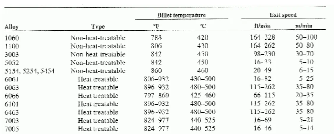
The extrusion parameters, such as ram speed and billet pre-heat temperature are directly dependent on the type of alloy. Saha [Saha,2000] gives an example of typical extrusion parameters for common aluminium alloys (Table I. 1). It is important to underline that the extrusion conditions, especially the exit speed and surface quality, are fully dependent on the complexity of the shape. A detailed control of each parameter can reduce the defects in the final product; such as blisters or cracking.
Chapter I: State of the art and scope of the research work
14
Table I. 1 : Typical values of billet temperatures and extrusion speed of extruded aluminium alloys.
[Saha,2000]
Practically, the die and the tooling supports (backer and holder) must be pre- heated in specific ovens located in the vicinity of the extrusion press (Table I. 2). This practice has two main objectives: the first one is to avoid any heat loss at the beginning of the extrusion process, the second is to achieve a specific toughness to avoid early fracture. The following table reports some examples of preheating parameters employed in extrusion processing.
After pre-heating, the die is quickly transported and assembled into the holder of the extrusion press. After extrusion of a specific profile, especially for hollow dies, the tool is removed and uniformly cooled before being cleaned in a bath of hot caustic soda.
Table I. 2: Preheat temperature and times for aluminium extrusion tooling. [Bauser et al.,2006]
These preliminary remarks on the fundamentals of the extrusion technology highlight the importance and the complexity relative to the choice and design of an extrusion die. A well defined hot working material and a specific heat treatment must be employed to ensure a long service life validating some specific requirements such as:
• Toughness at high temperature;
• High mechanical resistance at high temperatures (Yield strength, creep and fatigue resistance);
• Hot wear resistance;
• Thermal conductivity;
• Corrosion and oxidation resistance.
The validation of these specific requirements guarantees an optimal extrusion speed and an appropriate quality of the product based on a dimension stability and shape accuracy.
II.3 Hot work steels for extrusion dies: state of the art.
Due to severe processing conditions and complex mechanical loading, the die is considered as the most critical element of the extrusion equipment [Reggiani et al.,2010].
Significant focus and attention is paid in die development activities. From a material point of view, the hot work tool steel grades are still today considered to represent 90% of the total extrusion die consumption. The expression “Hot working tool steels” cover a large class of alloyed steels which are dedicated to different industrial applications for the hot working of metallic materials. In general, AISI H11 and H13 steels and their related grades are employed for aluminium extrusion tooling [Gutovskaya,2003]. These steel grades belong to the class of 5% chromium hot work steels. Chromium confers to the material good hardenability and temper resistance at the high working temperatures. The composition of the steels, traditionally employed for extrusion tooling, is reported in Table I. 3 :
Steel Designation Alloying Elements
[DIN] W.Nr AISI C Si Mn Cr Mo Ni V
X36CrMoV5-1 1.2340 H11 0.36 0.35 0.36 5.06 1.25 0.06 0.49 X37CrMoV5-1 1.2343 H11 0.37 0.92 0.49 5.05 1.25 0.20 0.47
X40CrMoV5-1 1.2344 H13 0.40 1.0 0.4 5.3 1.3 - 1.0
X55NiCrMoV7 1.2714 L6 0.55 0.25 0.8 1.1 0.5 1.65 0.1
Table I. 3:Chemical composition of Hot Work Steels. [Delagnes,1998]
AISI H11 steels are used because they exhibit high tensile strength at elevated temperature and a good fracture toughness as well as thermal conductivity (26-29 Wm-1K-1 at 200- 600°C).
X55NiCrMoV7 steel is characterised by high fracture toughness and an elevated ductility at high temperatures (mechanical shock resistance). Its application, anyway, is limited by the hardness decrease at temperature closed to 400-500°C.[Oudin,2001]
The alloying elements, such as Mo and V are employed to obtain the required high strength at the working temperatures, limiting softening mechanisms. In general, these elements react with the carbon to form carbides like M7C3, M23C6, M6C and MC, where M is the metal alloying element. The distribution of carbides, especially at grain boundaries, must be carefully controlled to achieve a uniform toughness through the bulk of the tool. For this reason, the production methods for hot working steels have been improved by the use of the electro-slag remelt steel-making process (ESR) which ensure, on top of a good control of impurity levels, a fine and uniform grain structure.
The basic operations of heat treatments of hot work steels are divided into four specific
Chapter I: State of the art and scope of the research work
16
hollow dies can be rough-machined from annealed hot working steels.[Bauser et al.,2006]
For this reason, an annealing treatment is performed at a temperature prone to release residual stresses and obtain a uniform distribution of globular carbides before manufacturing starts.[Delagnes,1998]
Afterwards, an austenitization temperature in the range 990-1030°C is employed to ensure a complete transformation of the ferritic structure. Cooling from the austenitizing temperature must be quick enough to minimize the formation of bainite that tends to embrittle the material causing a premature cracking. After quenching, the structure is unstable and brittle: steels must be tempered to achieve the targeted mechanical properties (such as toughness). A two-stage tempering is commonly employed for the hot work steels.
The first stage is run at a temperature in the range 550-600°C in order to induce a complete transformation of the residual austenite in secondary martensite and an increase in the toughness. The second tempering temperature (higher than the first one) is chosen according to the required hardness: this process guarantees the thermal stress release and the precipitation of uniformly distributed secondary carbides prone to improve the mechanical properties. Note that in the case of X55NiCrMoV7 only one tempering is performed as the material shows a continuous decrease of hardening during this final treatment.
Table I. 4 and Table I. 5 report, respectively, the heat treatment procedures selected for the traditional hot work steels and the resulting mechanical properties measured at room temperature.
Steel Austenitization First Tempering Second tempering
Hardness (HRC)
875°C/1h/OIL 605°C/3h/ AIR - 42
X55NiCrMoV7
875°C/1h/OIL 511°C/2h/ AIR - 47
900°C/1h/AIR 550°C/2h/ AIR 625°C/2h/ AIR 42 900°C/1h/AIR 550°C/2h/ AIR 610°C/3h/ AIR 44 900°C/1h/AIR 550°C/2h/ AIR 601°C/3h/ AIR 47 X37CrMoV5-1
900°C/1h/AIR 550°C/2h/ AIR 590°C/2.4h/ AIR 50
Table I. 4 : Table: Typical heat treatment for traditional hot work steels. [Delagnes,1998; Oudin,2001]
Steel Rp0.2 [MPa] UTS [MPa] Hardness (HRC)
X55NiCrMoV7 1100 1280 42
1100 1333 42
1200 1451 44
1335 1584 47
X37CrMoV5-1
1431 1733 50
Table I. 5 : Room temperature mechanical properties of hot work steels [Delagnes,1998].
Today, all extrusion dies are subjected to surface hardening and treatment in order to obtain a more uniform bearing surfaces and reduce wear damage. Nitriding is used since
many years to increase surface hardness. It consists in a simple diffusion of nitrogen at the surface of the die: the thickness of the diffusion zone range between 130 and 160 µm depending on the composition of the alloy.
Recently, CVD or PVD coatings, with titanium and chromium carbide as well as aluminium oxide, applied on the surface of extrusion tooling, have significantly improved die life. [Björk et al.,2001]
II.4 The extrusion cycle and die loading
The direct extrusion is the most frequently employed extrusion process. The material is loaded as form of billet and put into the container where it is pushed, by the ram, through a stationary die.
During a typical extrusion cycle, the ram force can be split into two components:
1. The Frictional Load (FR): that is consumed to overcome the container friction.
2. The Forming Load (FM): governed by section shape and die design and employed to form the material.
The last one could be considered stable over the ram stroke, whereas the frictional load varies with the ram position. Depending on the billet length, the container friction force is typically 30-40% of the maximum ram force [Oftedal,1998].
Total Extrusion Force= FM+ FR
The load displacement graph, reported in Figure I. 4, shows that a significant extrusion load is needed to start the cycle, due to the shear stress along the whole length of the billet.
As the stem moves forward, the area over which the friction acts is reduced as the billet becomes shorter. The reduction of the frictional component, over the press cycle, represents the reduction of the press force, as shown in Figure I. 4 (red curve).
Chapter I: State of the art and scope of the research work
18
distribution through the tool is not uniformly distributed. For this purpose, finite element analyses of hollow dies were carried out by Hydro Aluminium in order to point out the strain and stress response of the tool. All calculations were obtained using an isotropic hardening model and considering an evolution of the cycle with time. The “Beginning of the cycle”
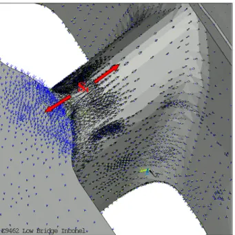
represents the instant when the billet starts flowing through the die, the “End of the cycle” is the extrusion of the final part of the billet and the “Dead cycle” stands for the unloading process time. Figure I. 5 shows that the deformation mode, emphasized by a bending behaviour, seems to be quite similar at the beginning and at the end of the cycle. The deformation is dominated by the billet pressure exerted on the porthole: this loading predominantly acts on the portholes bridges generating a bending moment (red and black arrows) which is subsequently transferred to the die plate creating high forces in the web area (blue arrows).[Dossin,2010]
Figure I. 5 : Deformation behaviour during Extrusion cycle. [Dossin,2010]
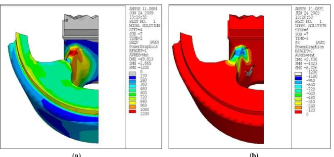
Figure I. 6 reports some calculations experienced on the porthole at the beginning (a) and at dead cycle (b). These analyses demonstrate that during the cycle (start and end cycle), the zone of transition between the bridges and the mandrel exhibits stress concentrations well above the yield strength of the material (called “Hot Spots”) generating a plastic deformation.
During the dead cycle, Figure I. 6 (b), the plastic strained hot spots are compressed when the tool is unloaded due to the elastic energy stored in the adjacent material. [Lange,1998]
(a) (b)
Figure I. 6 : stress distribution in die at the “Start” of the cycle (a) and at the “Dead of the cycle” (b)
These fluctuating stresses (tension/compression) become cyclic when multiple billets are extruded. In general, the extrusion stroke corresponds to cumulative loading/unloading cycles at a frequency 1-5 billets shaped every 10 min. For these reasons, the die is submitted to a typical low-cycle fatigue regime at a temperature that remains generally stable in the range 450-580°C. The extrusion tooling is then subject to a combination of thermal and mechanical loads that enhance the occurrence of damaging processes, namely low cycle fatigue and creep [Reggiani et al.,2010].
The cyclic alternate tensile and compressive stresses are simulated using Low Cycle Fatigue (LCF) tests conducted in a reversed total strain control. In such a way, the mechanisms of cyclic plasticity; enhanced by softening mechanisms at peak stress, can be evaluated in order to be close to the loading conditions of dies in service.
A trapezoidal waveform (Figure I. 7) was adopted as reference signal. The symmetric cycle is provided with an holding time (150s), at maximal strain, to assess for the extrusion loading conditions and a steady time (20s), at minimal strain, to take the unloading into consideration. The results of the experimental tests will be discussed in Chapter IV.
Chapter I: State of the art and scope of the research work
20
II.5 The failure mechanisms of the aluminium extrusion dies Fracture is one of the principal failure modes for extrusion dies and tooling: as mentioned before, the thermo-mechanical stresses act in a cyclic way, while the aluminium friction on the die surface induces wear damage on the bearing area. For this reason, the most common modes of in-service failure are fatigue, wear and deflection.[Qamar et al.,2008]
A statistical study about the relationship between die profile and modes of failure, presented by Arif [Arif et al.,2003], led to the conclusion that fatigue fracture is the main failure mode for all die shapes.
Typical fatigue failures are located at high stress concentration zones such as sharp corners, section changes or porthole bridges which are the most critical parts in the die. In this case, fracture initiation is not necessarily related to macroscopic defects in the material, but it is instantaneously followed by a rapid crack propagation. Specific microscopic investigations, reported by Hydro [Lange,1998], pointed out that this kind of “in service” die fracture lead to a sudden change of the wall thickness on the last extruded profile. The hot stress cracks extend as a network under the tool surface: this crack propagation is aided by the temperature differences between the core and the surface of the die that occur during the extrusion cycle. The presence of high stresses, combined with high stress-concentrations, lead to crack propagation and failure.
The second most significant failure is associated to friction damage, on the bearing surfaces, which is defined as a progressive wear of the material. The exposure to high temperature combined with friction between the extrusion material and the die enhances the development of adhesive and abrasive wear mechanisms. The formation of an adhesive layer is due to the high tendency of the aluminium to adhere on the steel surface, especially when the temperature increases. The layer is particularly rich in magnesium, aluminium, iron and silicon: the production of Fe-Al intermetallic compounds induces a continuous dissolution of the tool and a consequent failure.[Gutovskaya et al.,2004]
Other kinds of extrusion die failures include the deflection of the tool due to an excessive plastic deformation: the bending forces, acting on the hollow die, could lead to a displacement of the mandrel pole which can induce for instance an eccentricity defect on the rounded tube profile.
III The modular extrusion die: a new concept of extrusion tool
As discussed above, there is large variety of failure modes that can strongly limit the life and the efficiency of the extrusion tools. In the last few years, different developments to improve extrusion die performance were proposed by Hydro Aluminium, addressing the damage mechanisms of the die from a material selection and surface treatment point of view.
Surface treatments for die bearing address mostly wear issues employing specific CVD system in use since more than ten years. Over the last five years, different activities were ran with the objective to improve die performance considering both failure modes from a die
bulk material and surface treatment selection point of view. The main objective of these activities is to increase die life and reduce directly the connected ratio die cost/kg extruded.
Improving die stability can also generate significant profit through process reliability and productivity increase, as well as product quality stabilization (surface, dimensions).
In 2004, Hydro Aluminium Automotives Structures proposed a solution to limit the frequent failures of dies employed to extrude the 7000 series aluminium alloys. This innovative approach was based on the employment of various materials, with specific tailored properties, in different parts of the die.[Pasqualon,2010]
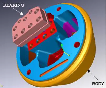
A so-called “Modular” extrusion die was designed and prototypes were tested. For this innovative die (see Figure I. 8 ), the area with strong thermo-mechanical (First module) loading was made with a Nickel-based Superalloy (Ni-SA) whereas in the bearing zone (Second Module), the insert was manufactured with a wear resistant material (such as high speed tool steel, hot working steel or precipitation hardened steel) optimised by the application of a specific coating.
Figure I. 8 : Modular Concept of Extrusion Die.
The introduction of this new concept of die brings various industrial and technological benefits. The employment of a stronger material, in the load carrying body parts, improves the die life and allow a higher productivity for extremely complex extrusion profiles and hard to extrude alloys. The application of hard coatings on wear affected parts reduces the die maintenance actions and improves the surface quality of the extruded product, due to the low roughness of the bearing surfaces and to the improved flow characteristics.
[Kindlihagen,2008]
For large section of 7000 series alloys several thousands of billets can be extruded with the same die. This result induces significant savings through die cost/kg massive reduction (die
Chapter I: State of the art and scope of the research work
22
The modular die was initially employed for the extrusion of automotive components. This industrial sector is characterised by an important volume of given sections which values long lasting extrusion dies.
In 2010, the modular die concept was employed, for the first time, in the Hydro Precision Tubing division to produce aluminium round tubes. Significant die life increase as well as process stability improvement have been achieved.[Pasqualon,2010]
The use of superalloys stands for a critical aspect of the Modular Die idea: these materials show high mechanical performances (creep and fatigue) at high temperature and good corrosion and oxidation resistance. For these reasons, they are known to be superior to the traditional hot work tool steels.
In particular, Inconel 718 was selected as the appropriate candidate material for the bulk structure: this alloy is the main wrought superalloy used in various industry [Gutovskaya,2003]. It is able to combine excellent tensile, fatigue, creep and rupture strength in the range of temperature where the die is operating (almost 550° C) [Special Metals]. Inconel 718 is also less expensive than different other superalloys such as Wespalloy and Udimet mostly because of its extensive worldwide usage in the Aeronautic and oil and gas fields. However some challenges are existing: manufacturing of Inconel 718 is very difficult and its thermo-chemical resistance to Al corrosion is low which forces the choice of another material for the bearing area.
The mechanical performances of this material will be investigated in this work and a particular study of the fatigue properties will be reported in Chapter IV.
III.1 Investigation of a real case of tool fracture
The service life of an extrusion die has a strong impact on the quality, efficiency and cost of a given extruded profile. The number of maintenance interventions (Die correction, Welding repair, die scrap), caused by tool defections, contributes to the commercial viability of the production. Generally, a die failure is declared when the tool has become completely inoperable or when it is unable to ensure its specific functions due to an advanced degradation: for this reason, the analysis of failure cases is a very important way for improvements in process economics and operating procedures. [Kazanowski,1998; Akhtar et al.,2010]
Figure I. 9 shows a detail of the fracture of an Inconel Modular extrusion die which was employed by Hydro Aluminium for the hot-extrusion of thin walled car bumpers of high strength aluminium alloys, from the A7000 series. A preliminary crack initiation was detected after the extrusion of 585 billets has been completed, the die was weld repaired and a new repair was required following the extrusion of 120 billets more, before being considered “out of service “.
Figure I. 9 :: The fractured part of the die
The tool exhibited a large crack in the transition bridge to the mandrel, where the bulk material is subject to high stress concentration, which induces a localised plastic deformation.
As reported by previous investigation [Gutovskaya,2003], the crack propagated along 40 to 60 mm and it was stopped by the increased width of the bridge closed to the mandrel, where the stress concentration is lower.
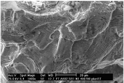
The crack was opened in order to investigate the fracture surfaces. A preliminary macroscopic analysis showed a flat surface with no necking, whereas a more detailed microscopic examination, performed by SEM, revealed the presence of fatigue striations with an average spacing of about 0,3-0,5 µm [Kazanowski,1998].
Figure I. 10 : SEM investigation of the fracture surface showing typical fatigue striations.
Considering the principal stress vectors, reported in Figure I. 11 and calculated by FEA in the die zone closed to the crack, it is assumed that the crack grew in length along a direction inclined by 45 degrees (high shear stress planes) with respect to the principal stress vector σ1 (Red arrows S1).
Chapter I: State of the art and scope of the research work
24
Figure I. 11 : Principal Stresses Vectors in the transition bridge of an hollow die.
This last detail confirms the hypothesis of a fatigue failure: the crack propagates long direction of fatigue propagation in Stage I. No evidence of intergranular fracture, possibly related to the coupled effects of the cyclic loading with the service environment, was detected.
The present investigation points out that fatigue is the relevant failure mode for Hollow extrusion die. The adoption of the modular concept has strongly delayed the occurrence of fatigue damage, considering that in some traditional steel dies only 25 billets were extruded before fracture initiates. However, the cyclic tensile/compressive mechanical loading is still a limiting factor for the die life.
For this reason, an important research activity, focused on the understanding and the improvement of the mechanical behaviour of the tool bulk material (Inconel 718) will be led in order to further increase die life, process stability and later on press productivity. A detailed description of the research objectives is given in the next paragraph.
IV Outlooks and Objectives of the project
In a traditional aluminium extrusion process, the tool is subject to extreme working conditions that strongly influence its service life: the variety of loading components, in terms of thermo-mechanical loading, and the continuous contact between the tool and the aluminium enhance the risks of wear and fatigue failures. The process of hot fatigue damage, during the extrusion operations is due to the alternation of tensile and compressive stresses, acting on specific zones of the die. This represents one of the most common cause of die failure, having detrimental impacts on the process efficiency especially through die cost [Subodh,2004].
In this economical challenge, the Modular Extrusion die is an innovative idea prone to improve die life and simultaneously reduce the directly connected costs. The application of
high performing material, Inconel 718, with thermo-mechanical and microstructural tailored properties stands for the technological step change. Even tough the technology has recently shown important benefits and good results in extrusion practice, this application is still at an early stage of its potential exploitation.
A more detailed knowledge on the mechanical behaviour of the bulk material, under extrusion conditions, might support further improvements of performances ensured by the modular die. From this point of view, two possible research options can be explored:
1. The investigation of the impact of the extrusion process such as extrusion speed, billet length, thermo-mechanical loading on the mechanical behaviour of the bulk material, the so called Material Extrinsic Parameters.
2. The optimization of the material properties to improve its strength under extrusion loading. This second objective could be achieved by modifying the Material Intrinsic Parameters such as grain size, precipitates morphology through thermo- mechanical treatments in order to adapt the material to the specific conditions imposed by the extrusion process.
The material development becomes the first step in increasing productivity and efficiency of an extrusion die. This represents the main objective of this study that will be addressed by a multidisciplinary approach including metallurgical, chemical and mechanical experiments.
In the last fifty years, considerable studies have been performed to address the cyclic behaviour of Inconel 718. This material, is employed in various industrial applications because of its high performances at elevated temperature.
The originality of the present work is based on the development of an optimized Inconel 718 alloy for specific applications, that is bulk material for extrusion die: which represents a technological jump in the employment for this superalloy in the field of tools.
From the scientific point of view, the isothermal Low Cycle Fatigue (LCF) tests are considered as the most representative testing facilities of the thermo-mechanical loading acting on the tool: various LCF conditions (strain amplitudes and strain rates) were so examined in order to address the various damage mechanisms occurring under cyclic solicitations.
The objective of this PhD work is to contribute to the development of die materials for aluminium extrusion for a continuous improvement of the productive capabilities of Hydro Aluminium to achieve a leadership in industrial products within a global market.
Chapter I: State of the art and scope of the research work
26
V References
[Akhtar et al.,2010] Akhtar, S. and Arif, A. "Fatigue Failure of Extrusion Dies: Effect of Process Parameters and Design Features on Die Life." Journal of Failure Analysis
and Prevention 10(1): pp. 38-49, (2010).
[Arif et al.,2003] Arif, A. F. M., Sheikh, A. K. and Qamar, S. Z. "A study of die failure mechanisms in aluminum extrusion." Journal of Materials Processing Technology
134(3): pp. 318-328, (2003).
[Bauser et al.,2006] Bauser, M., Sauer, G. and Siegert, K. "Extrusion 2nd Ed.", ASM International, p. 592, (2006).
[Björk et al.,2001] Björk, T., Westergård, R. and Hogmark, S. "Wear of surface treated dies for aluminium extrusion -- a case study." Wear 249(3-4): pp. 316-323, (2001).
[Delagnes,1998] Delagnes, D. "Comportement et tenue en fatigue isotherme d'aciers à outils Z 38 CDV5 autour de la transition fatigue oligocyclique endurance". PhD Thesis,
Ecole des Mines de Paris (1998).
[Dossin,2010] Dossin, S. "Stress Anlaysis of Hollow die plate". Unpublished Work Hydro Aluminium ECC (2010).
[Dwight,1999] Dwight, J. "Aluminium design and construction", E & FN Spon, p. 295, (1999).
[Gutovskaya,2003] Gutovskaya, J. "Material development for Aluminium Hot Extrusion Dies-AISI Premium H13 Tool Steel and Nimonic 90/PK 37 Nickel-Base Superalloys".
Phd Thesis, Norwegian University of Science and Technology (NTNU): 135 (2003).
[Gutovskaya et al.,2004] Gutovskaya, J., Solberg, J. K., Lange, H. I. and Andersen, L. H.
"Wear of Inconel 718 die during aluminium extrusion--a case study." Wear 256(1-2):
pp. 126-132, (2004).
[Kazanowski,1998] Kazanowski, P. "Die Performance Optimization through Understanding of the Surface Features of Fatigue Fractures". ET '08: the Ninth International
Aluminum Extrusion Seminar & Exposition (1998).
[Kindlihagen,2008] Kindlihagen, A. "Modular die concepts: Cost-Benefit analyses".
Unpublished work, Hydro Aluminium ECC (2008).
[Lange,1998] Lange, H. I. "Low Cycle Fatigue and creep testing of Hot Working Tool Steels at service temperature". Unpublished Work SINTEF Material Technology (1998).
[Oftedal,1998] Oftedal, K. O. "Loads acting on the tools". Unpublished Work, Hydro Aluminium Extrusion (1998).
[Oudin,2001] Oudin, A. "Thermo-Mechanical Fatigue of Hot Work Tool Steels ". PhD Thesis, Ecole Nationale Superieure des Mines de Paris (2001).
[Pasqualon,2010] Pasqualon, M. "Extrusion dies material and surface treatment developments". Unpublished Work, Hydro Aluminium PTTC (2010).
[Qamar et al.,2008] Qamar, S. Z., Sheikh, A. K., Arif, A. F. M., Younas, M. and Pervez, T.
"Monte Carlo simulation of extrusion die life." Journal of Materials Processing Technology 202(1-3): pp. 96-106, (2008).
[Reggiani et al.,2010] Reggiani, B., Donati, L., Zhou, J. and Tomesani, L. "The role of creep and fatigue in determining the high-temperature behaviour of AISI H11 tempered
steel for aluminium extrusion dies." Journal of Materials Processing Technology 210(12): pp. 1613-1623, (2010).
[Saha,2000] Saha, P. "Aluminum Extrusion technology", ASM International, p. 259, (2000).
[Special Metals] Special Metals "Inconel Alloy 718" (consulted webpage in March 2011) http://www.specialmetals.com/documents/Inconel%20alloy%20718.pdf.
[Subodh,2004] Subodh, K. "Technical Solutions for the Aluminum Extrusion Industry".
Eighth International Aluminum Extrusion technology (2004).
[Xianghong et al.,2006] Xianghong, W., Guoqun, Z., Yiguo, L. and Xinwu, M. "Numerical simulation and die structure optimization of an aluminum rectangular hollow pipe
extrusion process." Materials Science and Engineering: A 435-436: pp. 266-274, (2006).
Chapter I: State of the art and scope of the research work
28
Chapter II
Microstructure and mechanical properties of Inconel 718 alloy
“La bibliographie se fait après et non avant d'aborder un sujet de recherche”
Chapter II: Microstructure and mechanical properties of Inconel 718
30
Chapter II: Microstructure and mechanical properties of Inconel 718
VI Introduction
Nickel-based superalloys have been developed during the last 50 years in order to satisfy the different service requirements concerning, above all, the aeronautical and energy applications.
The aim of this literature review is to give a synthetic view of the wide variety of researches that have been previously carried out, in order to understand the mechanical and microstructural properties of the alloy. This preliminary chapter is considered as a pertinent support for the interpretation of the experimental results that will be reported in the second part of the manuscript (Chapter IV and Chapter V).
In the first part of the chapter, attention is focused, prevalently, on the review of the main microstructure dependent effects relative to:
• the alloying elements;
• the secondary phases and their strengthening effects;
• the thermal treatment parameters.
The second part deals with the mechanical properties of the alloy, with a particular interest on the cyclic behaviour. An examination of the main microstructural degradations associated to cyclic loading will be discussed in details, pointing out their effects on the global fatigue performances.
In the description of the different topics, a particular attention will be given to the alternative solutions (alternative thermal treatments, composition changes, forming processes) that were proposed by previous works in order to extend the domain of application of Inconel 718.
VII The nickel based superalloys
The nickel base superalloys represent a class of material that were developed to fullfill a need for stronger and more corrosion resistant alloys for high temperature applications.
These superalloys associate a good workability (castability, thermal treatment sensitivity, machining, coating…) to a high mechanical strength at elevated temperature, typically above 540°C, where the standard hot work materials (Steels, Titanium alloys, copper..) fail to operate [Guedou,2009].
Chapter II: Microstructure and mechanical properties of Inconel 718
32
very beneficial as nickel, in contrast to iron and titanium matrices, does not show allotropic transformations that might destabilize the structure, especially at high temperatures. The trend to form adherent thermally growth oxide (TGO) guarantees a good resistance against environmental attack by harmful elements such as oxygen and sulfur.[Decker,2006]
The hardening γ’ phase shows a rapid and homogeneous growth in the range of 12-300 nm: the slight lattice mismatching with the matrix increase the resistance to the dislocation movement, limiting the deformation process under high loads. In addition, the face-centred- cubic (fcc) crystal structure generates multiple slip systems assuring a good ductility and formability with minimum texturing. [Decker,2006]
Typical application of nickel base superalloys is the aerospace, industrial gas turbine and marine turbine industry, where the service temperature is closed to the melting point of the material. In addition, their high strength, coupled with a good corrosion resistance, allows their application in the biomedical field.
The future development of the nickel base superalloys will be focus on the optimisation of their general properties to fit a specific application or process [Donachie,2002]: this is the challenge that we are concerned with, for the present work, in order to optimise the material to the specific solicitations imposed by the extrusion process.
VIII Metallurgy and composition of Inconel 718
Inconel 718 is a nickel base superalloy initially introduced by Herbert Eiselstein in 1959.
Concerning chemical composition, this material differs from the other Ni base alloys as it contains iron (18%), which influences the precipitation process and some Nb (5%), which contributes to the hardening mechanisms [Alexandre,2004].
The alloy composition (Table II. 1) is based on a variety of alloying elements, each of them have a specific role to adjust material properties. Some elements, such as Nb, Al and Ti, take part in the formation of hardening phases. Others, like Cr, contribute to the oxidation resistance, whereas Mo enhances the mechanical resistance of the austenitic matrix at room temperature, but also at high temperature. [Slama et al.,2000]
Element [%]
Ni C Cr Fe Nb Mo Ti Al
Min Base 0.02 17.00 15.00 4.75 2.80 0.75 0.30
Max Base 0.08 21.00 21.00 5.50 3.30 1.15 0.70
Table II. 1 : Chemical composition of Inconel 718 alloy (% weight).
The strengthening effects are ensured by the precipitation of the γ” phases, Ni3Nb, with a body centred tetragonal (D022) crystal structure and an average size in the range 200-600 Ǻ (Figure II. 1). The precipitates are coherent disk-shaped particles that form with an approximate thickness of 50-90 Ǻ. In Inconel 718, the main contribution to hardening is
related to the coherency strains between γ” and the matrix. The crystal parameter misfit becomes more significant (~3%) along the tetragonal axis, as compared to the strain obtained on the plane of the disk (~1%). This element provides a higher strength than that associated to a traditional LI2 precipitate such as γ’. The precipitates have the following orientation relationship with the matrix: ([110
−
]γ // [110
−
]γ” and (111)γ // (112)γ” where the c axis of the tetragonal cell could be aligned along the three <001> directions of the matrix. In such a way, three variants of γ” can be detected in agreement with the following orientations:
Variant 1: [001] γ” //[001]γ; Variant 2: [001] γ” //[010]γ; Variant 3: [001] γ” //[100]γ [Strondl et al.,2008; Niang,2010]. Figure II. 1 illustrates the morphology of the three variants of γ” phases Figure II. 1(b).
Figure II. 1 : Unit cell of DO22 structure (γ”-Ni3Nb) structure and arrangement of atoms in the (111) plane (a) [Sundararaman et al.,1994], various variants of γ” phases detected in Inconel 718
microstructure (b) [Alexandre,2004].
The strengthening mechanism is completed by the presence of the γ’ phase , which is common to all nickel based superalloys, displaying a primitive L12 structure (Figure II. 2) with Aluminium atoms at the cube corners and Nickel atoms at the centres of the faces.
Figure II. 2 :Unit cell of LI2 (γ’) precipitates and distribution of atoms on the (111) close packed plane (a) [Andrieu,1987], TEM image in dark field conditions of γ’ and γ” particles (b) [Bor et al.,2010].
In the austenitic superalloys, the γ’ and γ” (A3B) precipitates, due to a stacking sequences similar to that of the matrix, are the only phases prone to exhibit a homogeneous and coherent precipitation. The alloy contains about 15% of γ” and 4% of γ’: the γ” precipitates
![Figure I. 1 : Schematic representation of the Extrusion process. [Dwight,1999]](https://thumb-eu.123doks.com/thumbv2/123doknet/3670005.108605/20.892.254.667.129.372/figure-i-schematic-representation-extrusion-process-dwight.webp)
![Figure I. 3 : Single cavity two parts porthole (a) die with six ports to produce aluminium hollow sections [Bauser et al.,2006] and schematic representation (b) of the welding chamber of a hollow die](https://thumb-eu.123doks.com/thumbv2/123doknet/3670005.108605/21.892.163.780.414.622/figure-single-porthole-produce-aluminium-sections-schematic-representation.webp)
![Figure I. 5 : Deformation behaviour during Extrusion cycle. [Dossin,2010]](https://thumb-eu.123doks.com/thumbv2/123doknet/3670005.108605/26.892.122.797.453.675/figure-i-deformation-behaviour-extrusion-cycle-dossin.webp)
![Figure II. 1 : Unit cell of DO 22 structure (γ”-Ni 3 Nb) structure and arrangement of atoms in the (111) plane (a) [Sundararaman et al.,1994], various variants of γ” phases detected in Inconel 718](https://thumb-eu.123doks.com/thumbv2/123doknet/3670005.108605/41.892.146.795.373.592/figure-structure-structure-arrangement-sundararaman-variants-detected-inconel.webp)
![Figure II. 3 : Unit cell of DO a (δ –Ni 3 Nb) structure (a) [Sundararaman et al.,1994], needle-like morphology of delta precipitates at the grain boundaries (b)](https://thumb-eu.123doks.com/thumbv2/123doknet/3670005.108605/42.892.213.758.282.487/figure-unit-structure-sundararaman-needle-morphology-precipitates-boundaries.webp)
