Design and Manufacture of Plastic Markers for
Agile Atoms DNA Set
by
Joanna So
Submitted to the
ARcvE
MASSACHUSETTS INSTITUTE OF TECHNOLOLGYJUN 2 4 2015
LIBRARIES
Department of Mechanical Engineering
in partial fulfillment of the requirements for the degree of
Bachelor of Science in Mechanical Engineering
at the
MASSACHUSETTS INSTITUTE OF TECHNOLOGY
June 2015
@
Joanna So, MMXV. All rights reserved.
The author hereby grants to MIT permission to reproduce and to
distribute publicly paper and electronic copies of this thesis document
in whole or in part in any medium now known or hereafter created.
Author ...
Signature redacted
Department of Mechanical Engineering
May 8, 2015
Certified by ...
Signature redacted
Prof. J. Kim Vandiver
Dean for Undergraduate Research
t
A
Thesis Supervisor
Signature redacted
A ccepted by ... ...
Anette Hosoi
Professor of Mechanical Engineering
Design and Manufacture of Plastic Markers for Agile Atoms
DNA Set
by
Joanna So
Submitted to the Department of Mechanical Engineering
on May 8, 2015, in partial fulfillment of the
requirements for the degree of
Bachelor of Science in Mechanical Engineering
Abstract
My thesis focused on the design and manufacturing of plastic parts for the Agile
Atoms DNA Set that is distributed by the MIT Edgerton Center. The design of the
parts had to be easy to manufacture in-house, be easily differentiated, and be able to
endure multiple use cycles. Many design aspects were discussed with the curriculum
developer at the MIT Edgerton Center. The process of the mold design and machining
is outlined here with suggestions for improvements for future iterations. The mold
designs are completed, the molds have been machined, and production runs have
commenced.
Thesis Supervisor: Prof. J. Kim Vandiver
Title: Dean for Undergraduate Research
Acknowledgments
I would like to thank Professor J. Kim Vandiver and Dr. Kathy Vandiver for their
ad-vice and support throughout this project. I would also like to thank Patrick
McAtam-ney for all of his help in the machine shop. I appreciated his wealth of knowledge in
making the molds and conducting production runs for the parts. Finally, I would like
to thank the Edgerton Center for their support and for allowing me to use their 3D
Contents
Contents
List of Figures
1
Introduction
2 Design Approach
2.1 Functional Requirements . .2.2
Phosphate Marker Design
.2.3
Nucleotide Marker Design
.3 Mold Design and Manufacturing
3.1
Mold Design . . . .
3.2 Preparing the stock . . . .
3.3 Mold Fabrication . . . .
3.4 Mold Alignment . . . .
3.5 Ejector Pins . . . .
3.6 Troubleshooting . . . .
3.6.1
Snapping Issues . . . .
3.6.2
Flashing Issues . . . .
4 Injection Molding
4.1
Clamping Force . . . .
7
9
11
13
14
15
18
19
19
21
24
26
27
28
28
29
31
34
. . . .
. . . .
. . . .
4.2 Injection Parameters . . . .
34
4.3 Cooling Time . . . .
35
4.4 Adjusting Ejector Pins . . . .
36
5 Summary and Conclusion
39
A Detailed Engineering Drawings
41
B Injection Molding Parameters
45
B.1 Phosphate Marker
. . . .
46
B.2 Nucleotide Marker . . . .
47
List of Figures
2-1 Figures a and b show the current DNA parts to which the new markers
attach. Figures c and d show the new markers attached to the current
D N A parts. . . . .
14
2-2 Phosphate marker and nucleotide marker with snap fit section and tag
section labeled . . . .
16
2-3 Example of different snap fit angles for the phosphate marker . . . . .
17
2-4 CAD renderings of initial designs and different tag section orientations
17
3-1
Example of a standard mold showing the cavity and the core
[3]
. . .
20
3-2 Figures a and b show the original parting line. Figures c and d show
the new parting line. The core is on the bottom and the cavity is on
the top. ...
...
21
3-3 Mastercam drawings of the phosphate marker and nucleotide marker
m old . . . .
22
3-4 Phosphate marker and nucleotide marker lined up over the ejector pin
h oles . . . .
23
3-5 Images showing the two different methods for cutting the mold blanks
down to size. Photographs by author. . . . .
23
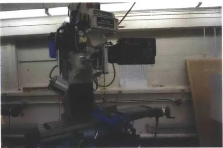
3-6
Haas machine in Area 51 used to machine the mold. Photograph by
3-7 ProtoTrak machine in Area 51 used to ream the holes. Photograph by
author... ... ...
. . .. .. ....
. .
25
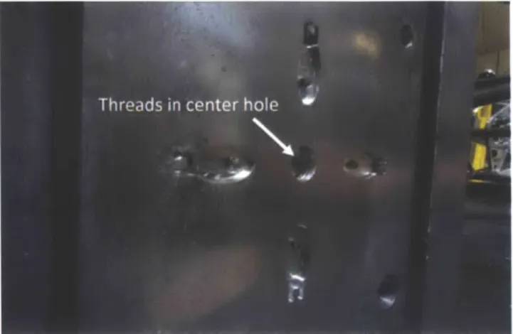
3-8 The core side with threads in the center hole. Photograph by author.
26
3-9
A misaligned part. Photograph by author. . . . .
27
3-10 Ejector pins shown above with the 3/32" on the left and the 0.043"
shoulder pin on the right. Photograph by author. . . . .
28
3-11 Example of snapped part during production . . . .
29
3-12 The difference between not having a shim (left) and adding a shim
(right) is shown above . . . .
30
3-13 Photo of shim used . . . .
30
4-1 The Battenfeld PLUS 250 Unilog 1020 in Area 51. Photograph by
author.... .. . . .
.. .... ... .
.. .... . 31
4-2 Image demonstrating how the ejector pin plate and the core side MUD
frame attach together. The ejector pins can be seen between them.
Photograph by author. ...
...
32
4-3 Diagram outlining the main processes during injection molding [2]
.
.
33
4-4 The control panel for the Battenfeld PLUS 250 Unilog 1020. Each
square is an image which represents a step in the injection molding
process. Photograph by author. . . . .
33
4-5 Image 1 from the control panel. Photograph by author. . . . .
34
4-6 Images 3 and 5 from the control panel. These control the shot size and
the pressure build up. Photographs by author. . . . .
35
4-7 Image 4 from the control panel. Photograph by author. . . . .
36
4-8 Top: Photo showing where to adjust the pins on the injection
mold-ing machine. This is shown by the circle. Bottom: A labeled photo
showing how to adjust the withdrawn and ejected length of the ejector
Chapter 1
Introduction
The Edgerton Center at the Massachusetts Institute of Technology (MIT) was
es-tablished in 1992 to give students the opportunity to learn by doing. This extends
to students from kindergarten to high school through the Mind and Hand Alliance,
which develops programs and hands-on educational materials to support K-12
edu-cation curriculum in science, mathematics, and technology (STEM)
[4].
One such example of the hands-on educational materials is the LEGO® DNA
Set, which is a kit of plastic, manipulable DNA and mRNA building blocks. Through
connecting these pieces together, students gain a better understanding of the molecule
functions. While these tools are useful in the classroom, the manufacturing process
has some issues. The original set was made using LEGO pieces that were
painstak-ingly superglued together by volunteers. This was both labor intensive and time
consuming. Furthermore, LEGO discontinued key parts causing the kits to be
back-ordered. As the parts were difficult to mass produce using the current process, the
solution was to design and manufacture injection molded parts. The design was
addressed by Bethany Lemanski's thesis [1] in which she redesigned the parts for
injection molding. These parts are currently being manufactured in Singapore. The
name for the new set is Agile Atoms DNA Set.
director of the Edgerton Center, and Dr. Kathy Vandiver, the Edgerton Center's
primary K-12 curriculum developer, wanted to add more parts to the kit to further
enhance the curriculum. As only a few of these parts are needed per kit, the decision
was made to produce these parts in-house at MIT. This thesis will detail the design
process for the extra parts, the mold fabrication process, and the injection molding
process.
Chapter 2
Design Approach
Three parts are being added to the Agile Atoms DNA Set. The first part attaches to
the phosphate, as seen in figure 2-1a, and therefore needs a circular snap fit shape. I
will refer to this first part as the phosphate marker. It marks the original two strands
of DNA so that the user can determine where these strands end up after replication.
The other two parts attach to the bases of the nucleotides, seen in figure 2-1b
and therefore require a rectangular snap fit shape. These parts will be referred to as
the nucleotide markers. They represent small molecules or atoms that bind only to
the bases and they must be easy to attach onto and to remove from the fully formed
DNA. Each nucleotide marker serves a different function:
1. One of these markers represents an oxygen radical that binds to the base
nu-cleotide, guanine, causing it to become damaged. As this base will either need
to be repaired or replaced for DNA to do its job, this marker enables users to
learn about the process of DNA repair.
2. The second nucleotide marker represents a methyl group. When a methyl group
attaches to a nucleotide, it may either promote or inhibit gene expression. This
marker enables users to learn about gene-environment interaction.
After discussion with the client, it was determined that this part could have the same design but be differentiated through color. This means using two molds instead of three, thereby decreasing manufacturing costs and time. Throughout the part design process, the mold designs were kept in consideration; certain design choices were made in order to make the molds easier to machine and to create a smoother injection
molding process. The final drawings for the designs can be found in Appendix A.
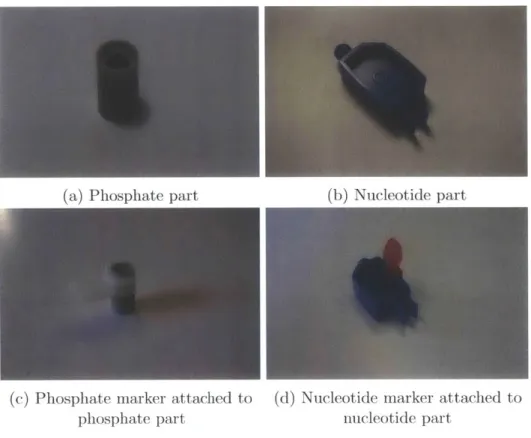
(a) Phosphate part (b) Nucleotide part
(c) Phosphate marker attached to (d) Nucleotide marker attached to
phosphate part nucleotide part
Figure 2-1: Figures a and b show the current DNA parts to which the new markers attach. Figures c and d show the new markers attached to the current DNA parts.
2.1
Functional Requirements
The two parts to be designed act as markers for specific molecules so that they are highlighted to students. The attachment to the DNA components is by means of a temporary snap fit that can endure multiple use cycles and user misuse. Through
discussions with the client, I was able to determine the main requirements for the
new parts.
One requirement was that the parts could be differentiated quickly. This would
make it easier for the user to know where the part should attach and it would be easier
to describe the part in a learning setting. Part of this differentiation came from the
geometry onto which the snap fit needed to fit. Another geometric differentiation was
the shape of the tag section. The third method to differentiate the parts was through
color. The clients wanted to make the phosphate marker white and the nucleotide
marker red or black depending on its function.
A second requirement was that the parts were of a good and easy size to handle
for children. It had to be child-friendly, both through its appearance and for safety
purposes. Choking hazard was not a consideration as the intended age of users is 12
and above. Minimizing sharp corners in the design allowed for a friendlier and safer
feel. This kit is designed for a long life and therefore must withstand multiple use
cycles and user misuse.
As the parts are essentially made up of two sections, the snap fit part and the tag
part, I will refer to these as the snap fit section and the tag section for the remainder
of the thesis. These are highlighted in figure 2-2. The legs of the snap fit section and
the gap-width are also highlighted.
2.2
Phosphate Marker Design
The constraining factor for the phosphate marker was the diameter of the phosphate
part that the marker would need to snap onto. Therefore, the inner diameter of
the snap fit section was set to this diameter. The thickness of the snap fit section
was'originally set to 1/16" as this was a standard thickness for all of the previously
made parts. Eventually this wall thickness was increased so that it would be easier
to machine the mold; tools with a larger diameter were usually longer and could
(a) Top view of phosphate marker (b) Top view of nucleotide marker
Figure 2-2: Phosphate marker and nucleotide marker with snap fit section and tag section labeled
therefore make deeper molds. Also, it was easier to find tapered tools with a larger diameter than tapered tools with a smaller diameter. The tapered tools would allow draft to be added to the molds so that the part would come off more easily.
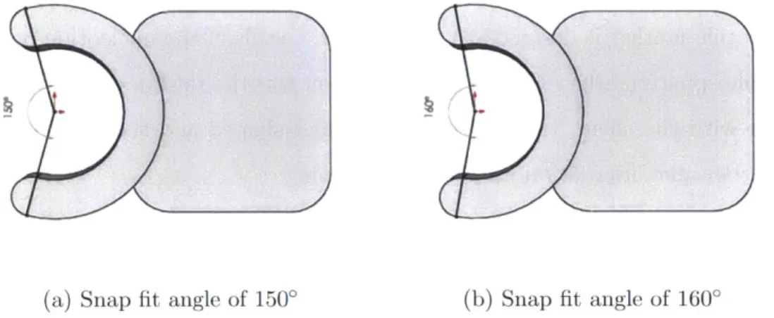
As the snap fit section is circular, the angle of the snap fit determines the gap width between the ends. This was determined through 3D printing the part and testing which version was more secure. The snap fit angle had to be smaller than 180'
or else the snap fit section would not hold onto the phosphate part. However, having a small snap fit angle would increase the displacement of the
jaws
and, consequently, increase the stress on the snap fit section. I initially tried 1500 and 160', shown in figure 2-3, to test it out. From this, it was determined that 1500 was a good snap fit angle to use as the angle of 160' was looser.Moving onto the tag section, the clients wanted the phosphate marker to have a square-shaped tag. The corners were rounded for ease of tooling and to soften the look of the tag. There were two different orientation options for the tag section relative to the snap fit section as shown in the figure 2-4.
While Option 1, the vertical option, was initially preferred by the client because it was a little more natural to handle the part this way, the final decision was made
(a) Snap fit angle of 1500 (b) Snap fit angle of 1600
Figure 2-3: Example of different snap fit angles for the phosphate marker
(a) Option 1 with the tag in a vertical orientation
Figure 2-4: CAD renderings of initial designs
(b) Option 2 with the tag in a
horizontal orientation
and different tag section orientations
to use Option 2, the horizontal option. This decision was made with the mold in mind as it would be easier to find a large, short tool than a thin, long tool. The two options also show how rounding the corners gives a softer feel to the overall design.
With an increased thickness, the moment of inertia would increase as would the stress produced by displacing the jaws of the snap fit section. A stress analysis was run on the part in SolidWorks and it was determined that the stress on the part is
8 times less than the yield stress. Therefore, this part should be fine with many use
cycles before it fatigues.
2.3
Nucleotide Marker Design
The nucleotide marker is designed to snap onto the walls of the nucleotide parts. As
with the phosphate marker, the limiting constraint was the thickness of the walls. In
discussion with the client, the tag section was oval-shaped and the tag section was
placed in the same orientation for ease of machining.
For the snap fit section, the gap was deliberately undersized from the wall thickness
of the nucleotide part that it would snap onto. This meant that there would be a
tighter fit and that the legs of the snap fit section would be angled outwards. This
creates a deliberate stress on the part. Ideally, the legs would be long and thin to
reduce the stress. However, this led to other problems, namely from the users. It
would be difficult to control the orientation in which a person removed the marker
from the nucleotide. If rotated about the x-axis then the longer legs would be more
likely to snap off due to the increased displacement. For this reason, the legs of the
snap fit section were made shorter. Also, the thickness of the snap fit walls was
increased to make for easier tooling. It was difficult to find a thin tool that was long
enough to create this part and offered draft options to make it easier for the part to
be ejected from the mold.
A few different options were 3D printed to test the gap width between the legs for
the snap fit and the size of the oval tag. A gap width of 0.055" and total part length
of 0.72" were chosen, shown in Appendix A, because the snap felt secure and the tag
was more comfortable in our hands.
Chapter 3
Mold Design and Manufacturing
When designing a mold, one must consider shrinkage, the position and orientation
of the parting line, the position of the sprue, the runners, and the ejector pins. The
mold has two parts: the core and the cavity, which are shown in figure 3-1. The cavity
has a sprue hole and runner system as this is where the plastic is initially injected on
the cavity side. The core side has ejector pin holes. For this reason, when the mold
halves separate, the injected part must come away from the cavity and stick to the
core so that it can be properly ejected off the mold.
3.1
Mold Design
To account for shrinkage of the plastic, the entire part was scaled up by 1% so
that the mold was 1% bigger than the design. The parts would then shrink to the
correct dimension during cooling. After running the parts on the injection molding
machine, the scale up of 1% seemed just right. The parts were scaled up in SolidWorks
before being transferred into Mastercam, another computer application, which could
generate toolpaths for machining the mold.
Another important aspect of the mold is where the parting line is placed.
Origi-nally, the parting line was placed exactly at the center but this highlighted
misalign-Sprue a Runrw
Sy~twm
C avityside
SOtlStoioy
Side
Core
Adw
Movmg
Side
Standard Mold
Figure 3-1: Example of a standard mold showing the cavity and the core
[3]
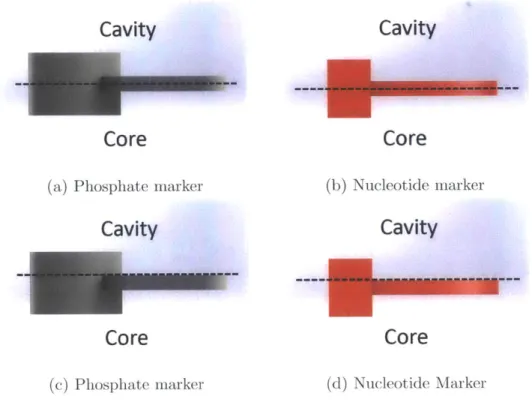
ments as both the snap fit section and the tag section were separated. Another issue was that the part did not always move away from the cavity with the core side. To counteract this, the parting line was moved to be underneath the tag area so that the entire tag was on the core side. As the majority of the part was placed here, there was a greater chance that the part would stay with the core mold. Figure 3-2 shows how the location of the parting line changed.
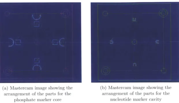
Given that the parts are small and that thousands of them needed to be produced,
I designed the mold in a way to allow several parts to be made at once. In the case of
both of these molds, I placed four parts on the mold in a circular pattern around the sprue hole. This configuration made the core and cavity part easier to make as they were essentially the same pattern. The layout is shown in figure 3-3. I chose to place the runner next to the tag area instead of the snap fit area so that the snap fit area was unaffected by any possible mistakes. Therefore, the snap fit section would work as designed. The tag section could afford to have a slight blemish of a gate mark.
The parts were designed so that they were conveniently positioned over ejector
Cavity
Cavity
Core
Core
(a) Phosphate marker (b) Nucleotide marker
Cavity
Cavity
Core
Core
(c) Phosphate marker (d) Nucleotide Marker
Figure 3-2: Figures a and b show the original parting line. Figures c and d show the new parting line. The core is on the bottom and the cavity is on the top.
ejector pin holes on the MUD (Master Unit Die) frames. I discovered that the ejector pin holes were a few thousandths of an inch misaligned from the drawing. Therefore, the holes could not be added directly on the Haas machine. The misalignment also meant that the part needed to be positioned with tolerance on either side for the holes. The positioning of the parts over the holes can be seen in figure 3-4.
3.2
Preparing the stock
The injection molding machine can only take a 3.75" by 4" piece of stock. Aluminum
(6061-T6) was used because it was cheap and easy to work with. The stock used had
a thickness of 1". In the future, I would recommend starting with a slightly thicker stock, maybe about 1.5", as shims needed to be added later for a better clamping force. Two blanks need to be made per mold: one for the cavity and one for the core.
(a) Mastercam image showing the (b) Mastercam image showing the
arrangement of the parts for the arrangement of the parts for the
phosphate marker core nucleotide marker cavity
Figure 3-3: Mastercam drawings of the phosphate marker and nucleotide marker m1old
To prepare the stock, I cut it from the main stock so that was a little wider than
3.75". Then I used the ProtoTrak machine in Area 51 to machine the stock so that it
was rectangular with a width of 3.75" exactly. When facing, I had to be careful that everything was lined up correctly in the vice in order to avoid a small taper.
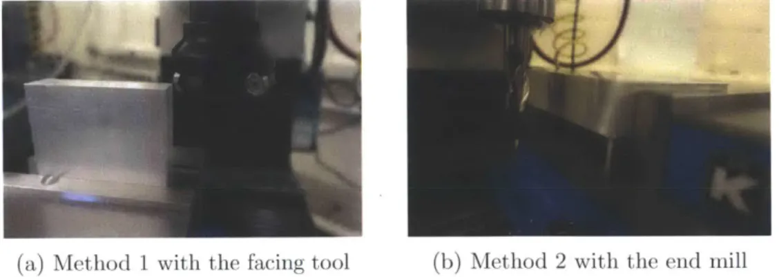
I machined the stock to size using two different methods, which are demonstrated
in figure 3-5:
1. Using the facing tool
(a) Mastercam image of the placement of the phosphate marker
over the ejector pin holes
(b) Mastercam image of the
placement of the nucleotide marker over the ejector pin holes
Figure 3-4: Phosphate marker and nucleotide marker lined up over the ejector pin holes
(a) Method 1 with the facing tool (b) Method 2 with the end mill
Figure 3-5: Images showing the two different methods for cutting the mold blanks down to size. Photographs by author.
3.3
Mold Fabrication
The design of the mold was completed in Mastercam, which generated toolpaths and G-Code. These toolpaths completed four parts on the mold, the pin holes in the corners, center holes and the runners in the cavity. The G-Code was imported into the Haas machine in Area 51, pictured in figure 3-6, to machine all of the molds. The snap fit section and the tag section were machined using different toolpaths. Because of this change, it was important that the toolpath for the shallower section overlapped slightly with the toolpath for the deeper section, otherwise a small burr was left behind. This burr was on the line separating the snap fit section from the tag section.
Figure 3-6: Haas machine in Area 51 used to machine the mold. Photograph by author.
The Haas machine completed most of the mold but the holes needed a few more passes on them. This was done on the ProtoTrak machine in Area 51 shown in figure
3-7.
Below is a list of holes that needed extra machining:
Figure 3-7: ProtoTrak machine in Area 51 used to ream the holes. Photograph by
author.
These holes had a snug fit over the pins so that the mold was aligned correctly in the injection molding machine.
2. The top left and bottom right corner holes were opened with a 9/32" drill bit and then counter bored. The resulting opening created a clearance hole for the screws, which held the mold in place on the injection molding machine.
3. The center hole on the cavity side was reamed with a tapered reamer from the
front side of the mold, which then allowed the sprue to be pulled out more easily in the event that it got stuck in the mold during injection molding.
4. The center hole on the core side was tapped to create thread holes on which the sprue could hold onto. When the cavity and core separated, the sprue would therefore be attached to the core side. This center hole also had a center ejector
pin, which pushed the sprue and other injected parts off of the core side. This
ejector pin sat underneath the face to allow room for the plastic sprue to grab onto the threads. The force from the center ejector pin was enough to push the sprue off of the threads during the ejection process. Figure 3-8 shows the
threads in the center hole on the core side.
Figure 3-8: The core side with threads in the center hole. Photograph by author.
3.4
Mold Alignment
Before adding ejector pins, I first checked the alignment of the mold by running them through the injection molding machine and seeing the results. With this check, I could see whether some runners needed to be extended slightly in order to completely
fill the mold.
Although the molds were made with reference to the center hole, for both the molds I made, there was always a slight misalignment. Figure 3-9 is an example of a misaligned part. It is suspected that the machine or MUD frames might be aligned incorrectly because the molds were generally misaligned in the same direction. To fix this, I widened the clearance holes and the pin holes to allow for more wiggle room with the mold. Then I was able to move the cavity and core a little upwards and sideways to fix the misalignment. The nucleotide marker cavity was actually refabricated so that the parts were shifted 0.01" in the negative x-direction. The refabrication helped get a better alignment without wiggling the molds around too much. This solution made the mold more production friendly because it could just
be placed in the machine and run. The phosphate marker took some adjusting to get
the right alignment each time it was placed in the machine.
Figure 3-9: A misaligned part. Photograph by author.
3.5
Ejector Pins
As mentioned above, there were slight misalignment issues with the molds so I chose not to drill out the holes for the ejector pins on the Haas machine when the mold was originally made. This is because it was unlikely the holes would have ended up in the correct position.
Instead, once the molds were aligned perfectly on the MUD frames, I drilled through the back of the ejector side MUD frame. This ensured that the pin holes in the mold were aligned with the ejector pin holes in the MUD frame. Once I had a spot drilled into the back of the mold, I was able to remove the mold, drill and ream the ejector pin holes. The holes should fit snugly around the ejector pin. If too large, the melted plastic would able to enter the hole, which could cause production issues
later.
Three different sized ejector pins were used. The center hole had a 0.25" ejector pin. The MUD frame was designed for a 3/32" ejector pin. The third ejector pin was a shoulder ejector pin. The diameter near the head piece was 3/32" so that it still fit
in the MUD frame. However, the end had a smaller diameter of 0.043". This allowed the ejector pin to fit inside the thinner sections of the mold, which tended to be the deeper parts of the mold. The different ejector pins can be seen in figure 3-10.
Figure 3-10: Ejector pins shown above with the 3/32" on the left and the 0.043" shoulder pin on the right. Photograph by author.
The ejector pins usually needed to be shortened for each mold. This was done using the bench grinder. The ejector pin should lay flush against the face of the mold.
If the ejector pin was too long, the injected part would have depression holes in it. If
the ejector pin was too short, a post would stick up out of the part.
3.6
Troubleshooting
While the part and mold design had been carefully thought through, some unexpected issues arose: snapping and flashing. Fortunately, I was able to solve these issues through ordering new parts or manufacturing extra parts.
3.6.1
Snapping Issues
While making the phosphate marker first, there was an unfortunate situation where one of the drill bits broke inside of the ejector pin hole, rendering it useless. When running the machine, it became apparent that there were not enough pins to push
out the part. The pins were placed on the tag section but the part would get caught in the snap fit section because it was much deeper. This situation caused problems where the parts would snap. An example of this is shown in figure 3-11.
Figure 3-11: Example of snapped part during production
I previously did not put any ejector pins in the snap fit section because it was
too thin for the 3/32" pins that the MUD frame was designed for. The solution was to use a shoulder pin, which had a 3/32" shoulder but became a 0.043" pin that fit inside the snap fit section. After this, the parts were able to come off without any major issues.
3.6.2
Flashing Issues
When first running the part, there was some flashing around the parts. Flashing is when there is excess material about the part due to a leakage of the material. A closer inspection of the molds when closed showed that the MUD frames, which the nolds were sitting in, were fully closed. This is demonstrated better in figure 3-12. This signaled that the cavity and core were not fully flush against each other. To fix this, a shim, shown in figure 3-13 was added behind the core side to increase the total thickness. This allowed the two mold halves to get better contact and, therefore, eliminate the flashing.
(a) No gap between MUD frames (b) Gap between MUD frames
Figure 3-12: The difference between not having a shim (left) and adding a shim (right) is shown above
Figure 3-13: Photo of shim used
Another flashing issue arose further along the production time. Parts of the mold were getting dented as occasionally, a part would become stuck and the mold would close in on it. As the mold was made out of aluminum 6061-T6, it was dented easily. The dented mold caused flashing because the face of the mold was no longer perfectly flat. To reduce the amount of flashing, these areas were filed slightly to roughen them up. However, a better solution would be to make the molds out of a harder material such as aluminum 7076-T61 or brass. Due to the time constraints, the parts were run with the dented molds and the small areas of flash were trimmed off.
Chapter 4
Injection Molding
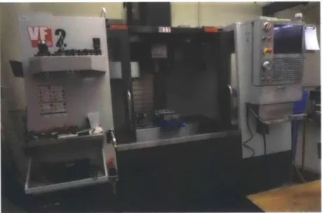
To manufacture the parts, I used the injection molding machine, a Battenfeld PLUS
250 Unilog 1020, in Area 51 shown in figure 4-1. Despite being made in 1996, the
machine had not seen much use. The machine has various safety features built in. For example, it will not run until the temperature condition is met, which means that the iold cannot be moved forwards and backwards even if the intention was not to run the machine but only check the mold.
Figure 4-1: The Battenfeld PLUS 250 Unilog 1020 in Area 51. Photograph by author.
For this particular machine, it should be noted that the parameters are mostly
entered using percentages. For example, for shot size, an input of 50 means that it is at 50% of the capability of the machine. Also, nothing will move until the gate is closed. The only part to be aware of is the space between the back of the sprue and the injector. There is not much room to work in if something needs to be unstuck, which could lead to burns. Additionally, the machine takes about 10-15 minutes to warm up completely.
Figure 4-2: Image demonstrating how the ejector pin plate and the core side MUD frame attach together. The ejector pins can be seen between them. Photograph by
author.
There are two MUD frames: an ejector side and a sprue side. The core goes on the ejector side and the cavity goes on the sprue side. Along the ejector side, there are additional plates for lining up the pins and a back plate so that all the pins move together. This is shown in figure 4-2. For the sprue side, there are no additional plates but the cavity center hole must be aligned with the sprue hole or else there are difficulties removing the sprue.
In the injection molding process, there are four key steps, outlined in figure 4-3. There are many parameters that control these steps and they can be found in the machine manual. I will go over the main parameters that I adjusted or thought more important in the process to achieving the perfect result at the end. The controls are separated into various images. Each image represents a different step in the injection
molding process. Figure 4-4 shows the control panel for the Battenfeld.
Figure 4-3:
Plastification Packing/Cooling
24
In eain pDemold/Eiection
Diagram outlining the main processes during injection miolding
[2]
Figure 4-4: The control panel for the Battenfeld PLUS 250 Unilog 1020. Each square is an image which represents a step in the injection molding process.
4.1
Clamping Force
One inportant parameter was the clamping force, parameter S2 in Image 1 seen in figure 4-5. The clamping force helped prevent flashing. This number was determined
by manually moving the two molds together to see the actual percentage for the
parameter S2. Then one or two percentage points was added to this actual value and inputted into the setting value to ensure that the clamping force is sufficient but not too much. This value changed for each mold set depending on the thickness of the core and cavity.
Figure 4-5: Image 1 from the control panel. Photograph by author.
4.2
Injection Parameters
The injection parameters pertained to the shot size and the pressure buildup. The shot size was found in Image 5 and the pressure was found in Image 3. Both images can be seen in figure 4-6. The shot size is parameter S2 and is the amount of plastic that is injected into the molds; the shot size was determined by trial and error and monitoring it during runs. If the actual number went down to zero, then the shot size was too small and it was increased. If the actual number went down to a number
larger than 2, then shot size was too large and it was decreased. The shot size was dependent on the barrel refilling, which meant that the change would only take effect once the barrel had unloaded and reloaded. Therefore, the run after the shot size had changed might not reflect the new shot size.
The packing pressure in Image 3 was determined by the parameter P1. The greater the number, the greater the pressure. Increasing the pressure sometimes required the shot size to also be increased to avoid short shot (too little material filling up the
mold).
(a) Image 3 from the control panel. (b) Image 5 from the control panel.
Photograph by author. Photograph by author
Figure 4-6: Images 3 and 5 from the control panel. These control the shot size and the pressure build up. Photographs by author.
4.3
Cooling Time
The cooling time affected how much the part shrunk on the mold. This was param-eter t3 in Image 4, shown in figure 4-7. Chapter 3 discussed snapping issues which sometimes occurred because the part had solidified too much. The cooling time was also a parameter to test and alter accordingly. In general, the longer the cooling time, the more the part shrinks and the harder the plastic becomes. This parameter affected how well the part ejected off the mold and how well the snap fit worked. If
the cooling time was too long, the part might have shrunk onto the mold, making it harder to remove.
Figure 4-7: Image 4 from the control panel. Photograph by author.
4.4
Adjusting Ejector Pins
There were various ways to adjust the ejector pins. The first, we saw in the previous chapter, was length; the ejectors pins could be shortened to the correct length by using a bench grinder. However, adding a shim meant that the length needed to be readjusted. However, instead of redoing the ejector pins, which were expensive, the amount that the ejector pins were withdrawn could be adjusted manually on the machine as shown in figure 4-8. The amount that the pins were moved forward is also adjusted in the same manner. To reach the right adjustment, the core mold was manually moved forward to the cavity. It did not necessarily need to touch the cavity depending on the mold thickness. Then the screws controlling ejector pin movement were loosened and adjustments made accordingly. This method was a very coarse way to make adjustments as this was all done by hand.
The velocity and pressure of the ejector pins also affected how well a part was removed. Determining velocity and pressure required finding a good balance and was
again, trial and improvement. Sometimes too much pressure caused an indent in the
part where the ejector pin was pushing against the part.
Figure 4-8: Top: Photo showing where to adjust the pins on the injection molding
machine. This is shown by the circle.
Bottom: A labeled photo showing how to adjust the withdrawn and ejected length of the ejector pins. Photographs by author.
Chapter 5
Summary and Conclusion
The purpose of this thesis was to design two new parts for the Agile Atoms DNA Set.
I have outlined the design with different shaped tags in order to make them easily
identifiable. The parts were designed for manufacturing so that it would be easy to
make the molds and remove the parts from the mold.
The machining process for the mold had some difficulties due to misalignments
with the injection molding machine. It was also difficult to cleanly drill out the ejector
pin holes and for each mold, one of the holes was useless after a drill bit broke inside
the mold. This error meant that it was harder to remove the part or that the part
was dammed off so fewer parts were made per cycle.
Given the time constraints for the orders of these parts, the production run started
early on. The current molds can produce about 12 parts per minute. The part designs
and the current mold designs work well. However, in the future, I would remake the
molds using a harder material to prevent further damage to the mold, which causes
problems during production. I would also place eight parts instead of four parts
around the mold to increase the production rate.
Appendix A
'Ann
.4946
.0950
R.0475
1500
R.1650
.6800-R 1 n0j
.5000
I. I~~~UNLESS OTHERWISE SPECIFIED: FINISH: DEBUR AND DO NOT SCALE DRAWING REVISION
DIMENSIONS ARE IN MILLIMETERS BREAK SHARP
SURFACE FINISH: EDGES
TOLERANCES:
LINEAR:
ANGULAR:
NAME SIGNATURE DATE TITLE:
DRAW CHK'D APPV'D 0
ors
u
____ G.A 1DWG NO,__i__ __
.__WG__
.Phosphate
M
arke
.0950
.1550
.7200-.9938
-- l T
.1563
.5375
.2-0
R.0750
.0300
.055
.0900
.062
1825
.237%
.3000
UNLESS OTHERWISE SPECIFIED: FINISH: DEBUR AND DO NOT SCALE DRAWING REVISION
DIMENSIONS ARE IN MILLIMETERS BREAK SHARP RVSO
SURFACE FINISH: EDGES
TOLERANCES:
LINEAR:
ANGULAR:
NAM SIGNATURE DATE TITLE:
DRAWN CHK'D APPV D MFG
![Figure 3-1: Example of a standard mold showing the cavity and the core [3]](https://thumb-eu.123doks.com/thumbv2/123doknet/14680575.559162/20.918.229.656.171.490/figure-example-standard-mold-showing-cavity-core.webp)