DESIGN AND ANALYSIS OF
A MULTI--MEDIA, MULTI-ACCESS DATA NETWORK by
John Christian vom Lehn
SUBMITTED IN PARTIAL FULFILLMENT OF THE REQUIREMENTS FOR THE DEGREES OF
BACHELOR OF SCIENCE and
MASTER OF SCIENCE at the
MASSACHUSETTS INSTITUTE OF TECHNOLOGY May, 1983
Qjohn Christian vom Lehn, 1983
The author hereby grants to MIT permission to reproduce and to distribute copies of this thesis document in whole or part.
Signature of Author - _ .... .
Department of Ele r cal Engineering and Computer Science UJMay 1, 1983
Certified by
.
- ..
.
.
.
.
Professor Jeff Spiro,Academi Thesis Supervisor
Certified by .
-
. . . .....
C.M. Puckette~,4- orporate anlpevelppment Center
Accepted '
.
..
.
.
..
Professe rthur C. Smith, Chahrman , Departmental Committee on Graduate Students
MASSACHUSETTS INSTITUTE OF TECHNOLOGY
DESIGN AND ANALYSIS OF
A MULTI-MEDIA, MULTI-ACCESS DATA NETWORK by
John Christian vom Lehn
Submitted to the Department of Electrical Engineering and Computer Science on May 3, 1983 in partial fulfillment of
the requirements for the degrees of Bachelor of Science and Master of Science in Electrical Engineering.
ABSTRACT
A local area network was designed, constructed, analyzed and improved. The network employed a modified token passing protocol, similar to a round robin approach, implemented in a bus structure. The network was designed to use either fiber optics or wire pair, or a combination of both, as the network transmission medium. Network stations were microprocessor-based, consisting of a central
pro-cessor, two slave processors and a shared memory resource. After an original working model was successfully constructed, the performance of the network, notably its efficiency, access delay, and throughput were carefully analyzed. Certain aspects of the protocol and hardware design were found to cause significant downgrading of performance. Based on the analysis, a revision of the network was proposed. As an empirical measure of the network's performance, a data traffic simulator was constructed and used to verify the conclusions of the analysis.
Work on the project was conducted at General Electric's Corporate Research and Development Center
in Schenectady, New York.
Thesis Supervisors:
Dr. Jeffrey H. Shapiro
Associate Professor of Electrical Engineering Mr. C.M. Puckette
General Electric Company
Table of Contents
Section I. Background and Terminology
Section II. Considerations for Network Design
Section III. Network Protocol
Section IV. Hardware Implementation
Section V. Analysis of the Prototype Network
Section VI. Simulation of Data Traffic
Section VII. Network Revisions
Section VIII. Conclusions
Appendix A
An Approach to Assembly Language Programming Appendix B
Implementation of the Network Bus References -2-6 12 16 26 73 88 96 107 109 127 135
List of Tables
II.1 Specifications of the Prototype Network 15 IV.1 Necessary Functions for Network Units 27 IV.2 Assignment of Necessary Function 36
IV.3 Station Memory Map 44
IV.4 Station I/O Map 44
IV.5 8257 Specifications 46 IV.6 8273 Specifications 47 IV.7 8741 Specifications 48 IV.8 8251 Specifications 49 IV.9 8085 Specifications 50 V.1 Definition of Variables 78
V.2 Calculation of Processing Times 85 V.3 Values of Variables for Prototype Network 87 VIII.1 Values of Variables for Revised Network 105 A.1 Assignment of Memory and I/O for HPTEST 116
-3-List of Illustrations
1.1 Interface Unit Functions 9
III.1-5 BIU Protocol (flowcharts) pp. 18-22
III.6 CCU Protocol (flowcharts) 23
IV.1 Basic Hardware Layout 35
IV.2 Possible SDLC Frames 41
IV.3 Detailed BIU Flowcharts pp. 51-63 IV.4 Detailed CCU Flowcharts pp. 64-67 IV.5 Detailed 8741 Flowcharts pp. 68-72 V.1 Bus Activity (with messages) 77 V.2 Bus Activity (no messages) 80 VII.1 Access Delay and Efficiency vs. Data Rate 98 VII.2 Revised Bus Activity (with messages) 103 VII.3 Revised Delay and Efficiency 106 A.1 IEEE-488 Interface Hardware Design 113 A.2 HPTEST detailed flowcharts pp. 117-121 A.3 Final Program for HPTEST pp. 122-126
B.1 Optical Tap Configuration 130
-4-Acknowledgements
Grateful acknowledgement is made of the contributions of Dr. Sanjay K. Bose, who designed the basic protocol for the network and supported the initial software programming, and to Mr. Eugene J. Orlowski, whose continuing technical assistance through the construction and demonstration of the network has been invaluable. Acknowledgement is also made of the assistance of Mr. C.M. Puckette of General Electric and Professor Jeffrey Shapiro of MIT whose patient supervision of this project provided a constant positive
incentive.
-5-I. Background and Terminology
A. Introduction
The simplest function of a data communications network is to transport data from one point to another. As data sources have become more complex, however, data communi-cation networks have been required to provide a wider range of functions, thus necessitating a higher degree of intelligence in the network itself. The concept of an in-telligent network is the foundation of the emerging industry of so-called "local area networks".
To date, there has been a great deal of work done in developing the concept, but little has been accomplished in the area of standardization [1]. Every major manufacturer in the computer industry, hoping to seize a large share of the new market, has proposed at least one network and cross-compatibility has been given little attention [2]. In addition to the competition roadblock, standardization has also been hampered by the fact that a major portion of these networks is not hardware but software, thus allowing a much wider range of possibilities.
Because of the relative newness of local area networks and the absence of any standard design, the creation of a local area network presents an interesting free-form problem. The network may be specified from the protocol level to the actual hardware based on design objectives alone; the problem becomes as much to determine what is needed as what can be done. Such a project was initiated at General Electric's Corporate Research and Development Center in 1981. This thesis report describes the creation of a local area network, from the initial specifications, through prototype construction, to performance analysis and construction of an improved network.
informa-tion as well as a record of the author's actual research. The remainder of this section is devoted to establishing needed terminology for description of the network. Section II discusses the general goals and limitations for local area network design and the reasons for choosing various system attributes in the prototype design. Sections III and IV are devoted to a general description of the prototype network, from a system and hardware standpoint, respective-ly. Sections V and VI detail the theoretical and actual performance of the prototype network, and Section VII describes changes made to the original network based on the analysis made. Section VIII is devoted to summary, including the applicability and future possibilities for the network. Two appendices are also included, the first describing the approach used in the software programming of the network, including example programs, and the second detailing the implementation of the network using both wire pair and fiber optics as the network medium.
The author was involved with the project from its beginning in June 1981, during which time the design objectives described in Sections II and III were determined, in concert with Dr. Sanjay Bose and Mr. Eugene Orlowski of General Electric. The author completed the hardware design is described in Section IV in 1981, and returned to the project in May 1982 to conduct the research described in the
remaining sections of this report.
B. Descriptive Terminology
While one of the goals of this report is to avoid use-less jargon and buzzwords, some uniquely-defined ter-minology will aid in describing the project. This terminology will be explained in the context of the basic function and structure of a local area network. First, and perhaps most difficult, is the definition of the term
"local area network" itself. Several papers have been written to this end [3], hoping to establish a basis for classification, but for the purposes of this report, a strictly functional definition will suffice: a local area network is system used to support data communication among several users, using a shared communication medium. Users here may include any of a wide variety of data sources with varying degrees of intelligence, or decision-making cap-abilty, including computers, data terminals, computer peripherals, instrumentation, and numerically-controlled machinery. The communication medium may be free space, single or multi-conductor wires, cables, or waveguides. Data in the communication medium may be broadcast to all units of the network, or forwarded from one unit to another. Broadcast type networks include bus structures and dendritic (tree-like, with branches) structures [4]. Forwarded-data networks include net structures, where data can take any of several paths to a given destination, and daisy-chain or ring structures [5].
The characteristic function of a local area network is found in the interface between the user and the shared communication medium. A common goal for a local area network is "transparency", meaning that the user need not be concerned with the network's operation (the network is unseen, or transparent); the user merely gives the network data with the understanding that it will be sent to the appropriate destination without the need for any additional instructions. All local area networks will provide intel-ligence for arbitration among users as they require use of the shared medium, as well as some mix of functions for the interface to the user. As shown in Figure I.l,these interfacing functions may include buffering
(temporary storage of data), packetizing (division of data into standard length units), error-checking (inclusion of a
Interface Unit Functions
Figure I. 1: Interface Unit Functions
-9-calculation based on the input which can be re-calculated at the destination), formatting (conversion of data into a standard form), routing (choice of path to destination), and translation (one code or data format to another). Obviously, for the network to achieve transparency, the network must perform a set of functions on data received from a source, or sender, and then invert these functions before data is relayed to the destination unit.
As has already been implied, there must be some set of rules that govern access to the shared medium. These rules are called the network protocol. In general, the network protocol can be viewed in a layered approach, covering everything from actual connections to the medium to commands given to the network for given applications [6]; however, for the purpose of this report, network protocol refers only to the rules governing access at the system level.
There are as many different network protocols as there are networks, yet there are two basic types worth distinguishing: random access and deterministic. A random access protocol allows units to send information as soon as they receive it, subject to some restrictions. Such a protocol is Carrier-Sense Multiple Access (CSMA) [7], in which a station with data to send first checks to see if the shared medium is being used, and if it is not, the station sends the data. Different propagation times among the various units may result in two messages being sent at once, causing a "collision." The protocol has further stipulation regarding operation in case of a collision, determining which unit may send again and which must wait. A deterministic protocol has rules which never allow two
units to transmit at once in correct operation. Examples of such protocols are Master/Slave protocols, in which a central unit, the master, commands other units, the slaves,
-10-to send or receive data. Other examples are -10-token-passing protocols, where the right to send data is contained in possession of the "token," which is a signal or code held and then passed among the units in the network [8].
Finally, some terminology is necessary for the description of the network units. The basic unit of the network is the interface unit. This unit contains all necessary intelligence for sending data and receiving data from the user, and in many cases, contains all intelligence necessary for the operation of the network. Other networks may include control units which ensure correct operation of the network. These units are generally much fewer in number than the interface units and act in a monitoring and command fashion.
This, then, is the composition of a local area network: interface units, optional control units, and a shared medium. The interface units connect users to the shared medium, allowing communication with other units. Access to the medium is governed by the protocol, which is implemented by the interface units and the control units.
-11-Section II. Considerations for Network Design
This section examines the design objectives for the prototype network and the reasons for many of the design choices. It should be pointed out that a considerable amount of the fundamental decisions described are subjective; other designers might attack the same problem in an entirely different way. The subjectivity arises out of the fact that, as with all engineering problems, the solution lies not in discovering the single perfect design, but in striking a balance between conflicting performance goals. Thus, this section is largely an account of the trade-offs associated with local area network design. The most obvious design trade-off involves simplicity: the simpler the network, the lower its cost, the smaller its circuit size, and in general, the greater its reliability. There is little need, however, to extrapolate the pure simplicity argument very far; a network must provide at least basic functions in order to be superior to conventional "dumb" circuitry. In general, these advantages are had by high speed and efficient use of network capabilities. More elegant designs can be justified by other features, such as interface flexibility, failure protection, easy expandability, and varying degrees of network transparency. An initial decision, therefore, is the scope of the network: what degree of elegance is justified by the projected market? For the prototype network, the approach was slanted toward simplicity, based on a desire to produce a working model as soon as possible, and also based on an assumption that many potential customers would be willing to forego advanced features in
favor of lower price. Thus the goal was set to achieve the best results from a small-scale system.
make some more quantitative decisions. Since the projected market was not the mainframe-to-mainframe network market which requires more elegant features, but the smaller scale control and instrumentation market, inquiries were made in regard to data requirements. A study [9] showed a need for regular transmission of short data messages, as opposed to infrequent, long messages. The large majority of messages were small (less than 256 bytes) and most devices were incapable of assimilating data at rates faster than fast terminals (about 20 kilobytes per second). A wide variety of user types was projected, with most receiving much more data than they send. Based on these reports, the design became more specified: a medium-speed, short message, medium utilization network.
The projected market also specified the operating environment: typically a harsh factory environment, where conductors might occasionally be severed, and where electro-magnetic interference is often a problem. Reliability needed special consideration. Finally, price was also an important issue: it was necessary to keep the network's cost well below that of the more elegant networks, which typically cost in the $800 to $1000 range per unit [10]. Clearly, a small price differential would not justify the reduced performance; the network needed to be about an order of magnitude less expensive.
At this juncture, some actual specification could be made. Because of the simplicity and price requirements, a medium-level (about 100K bits per second) network data rate was favored. Because of the relatively constant level of utilization and the acceptability of the lower network rate, a deterministic protocol was preferred. This is because, as will be shown in Section V, a deterministic protocol is capable of higher efficiency than random access protocols which exhibit instability beyond a certain level
of utilization. Although arguably more complex to implement, deterministic protocols offer the promise of more efficient use of slower transfer rates. The projected environment indicated a need for noise-immune fiber optics in some if not all parts of the network, and suggested advantages to a bus or dendritic structure over a ring structure, since a ring network would be rendered non-functional from a single break.
Further study indicated that a master/slave protocol was not preferred because of a perceived need for many units to communicate directly with one another; the necessary intervention by a master unit would cause a serious loss of efficiency. On the other hand, the need for reliable operation warranted some kind of monitoring function, supplied by a single control unit. The high incidence of "dumb" users indicated a need for a concentration of intelligence in the user interface to allow for a flexible exchange of data. The number of users was seen to vary widely, but many instances required only a small number of users, thus leading to the four stations of the prototype network. The combination of all these factors led to the initial specification shown in Table II.1; the actual implementation listed is the product of the final specifications described in sections III and IV.
-14-Specifications of the Prototype Network Network Network Structure Protocol Network Medium Network Interface Message format Acknowledgement Number of BIU's Network Data Rate Interface Data Rate Interface Functions
Packetizing Error-checking Translation
Alternate routing Max message length Buffer size Interstation distance Initial Bus Deterministic Peer-to-peer Central control Fiber optics Flexible < 32 100K bits/sec 9.6K bits/sec Var. length Shift and add ASCII encoding none 256 bytes loom -15-Actual Bus Token-Passing Broadcast mode
Single control unit Fiber optics Dedicated processor SDLC frames Positive only 4 64K bits/sec 19.2K bits/sec SDLC format 16-bit FCS ASCII only none 256 bytes 1024 bytes 0loo0m
Table II.1
III. Network Protocol
A. Bus Interface Units
As was stated in Section II, the desired protocol was one which would be deterministic, support peer-to-peer communication (as opposed to a master/slave arrangement), and operate in a bus structure. Although the first two requirements would seem to suggest a token-passing protocol, the third does not: a token-passing protocol is typically implemented in a ring structure. In that typical implementation, the token is actually no more than a message header. When an individual unit detects this unique header, it knows that it may append whatever messages it may have to send. Data flows in only one direction along the ring, and when a station sees a message addressed to it, it takes the message out of circulation by storing it and not forwarding it as it passes the collection of messages and the token to the next station. Since the inferiority of the ring for this design was sufficiently demonstrated, some changes were necessary in the token-passing scheme.
The principal difference between the ring and bus structures is access to data. In a ring, a station only receives from the preceding station; thus "possession" of the token is a logical concept. In a bus structure, all data is broadcast, that is, all stations receive the same data at roughly the same time. Thus, possession is not a viable concept for the bus structure. The solution to the problem lies in a redefinition of the right to send data. Fundamentally, all that is required is that each station have some unique condition, which it and all stations on the network will recognize, that entitles it to send data. The simplest form of this is a round-robin approach, each station transmitting in a pre-defined order. All that is
then necessary is some way for each station to keep track of what the order is, when it will have the opportunity to transmit, and when a particular station has completed activity in its present turn. Such a procedure is the basis for the algorithm used in the prototype network protocol.
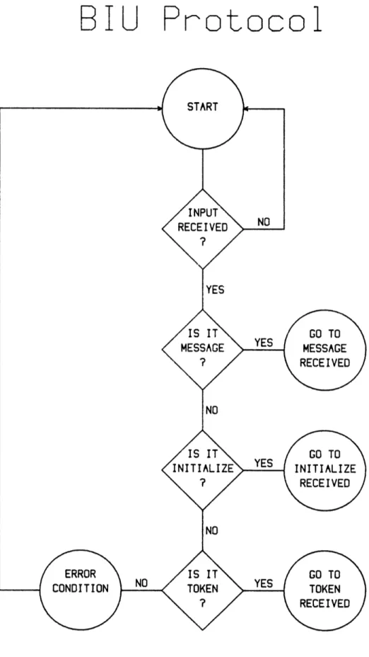
Each bus interface unit (hereafter BIU) is assigned a unique address, called MYADD, in the range 0 to 255. Each unit also keeps a count, called COUNT, of the number of turns completed. When COUNT matches MYADD, the BIU knows that it has exclusive right to transmit. It transmits whatever messages it may have received from the user, waits for acknowledgement from the various destinations, and then sends the token message, which indicates completion of the turn. If the BIU has no messages to send, it merely sends the token message. Each BIU also keeps a value called LIMIT, which is the largest possible value for COUNT. When COUNT exceeds LIMIT, the BIU resets COUNT to zero, and the cycle of turns begins again. The operation of this protocol is illustrated in Figures III.1-5.
The protocol as stated to this point deals only with access to the network medium. Of course, while the BIU is interacting with the network medium, it must at the same time be interacting with the user. This requirement will be more fully examined in Section IV, but it can also be seen in the flowcharts. In Figure III.1, it can be seen that the BIU must maintain a constant attention to the network medium, checking for an input. When an input is received, the type of data received is determined and appropriate action taken. In the case of a message received, the network sends an acknowledgement to the sender, and then must wait until the user is not busy before forwarding the message. For instance, the user may be in the process of transferring data when a message is received. Other network
B I U
Protoco
BIU:
Message
Received
Figure III.2: BIU Protocol--continued
-19-Received
Figure III.3: BIU Protocol--continued
-20-SET COUNT TO NUMBER
RECEIVED
BIU: Initialize
BIU: Token
Rece
i ved
BIU:
Send Message
Figure III.5: BIU Protocol concluded
-22-CCU Protoco
Figure III.6: CCU
Protocol
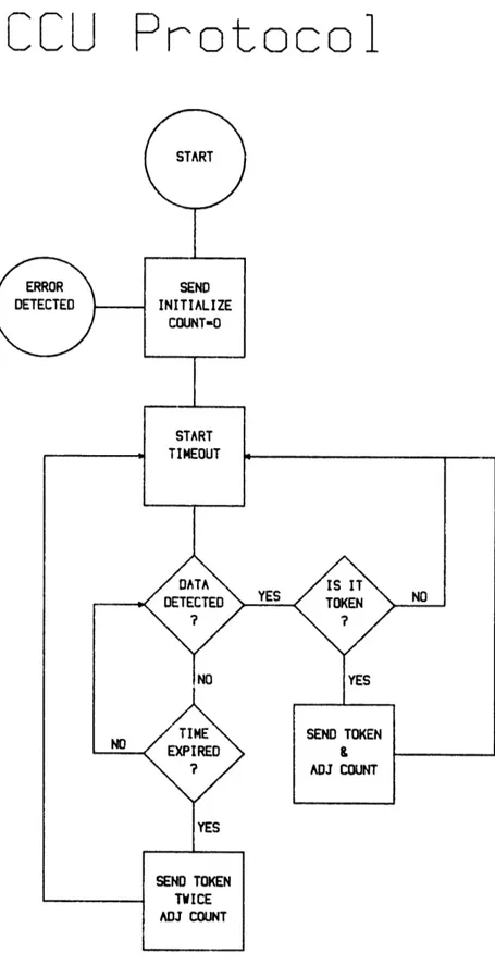
-23-activity remains transparent to the user, except in the case when the post-transmission timeout expires before an acknowledgement is received (see Figure III.5). In that case, the user is notified; otherwise, it may be assumed that transmission of all prior messages was successful. The inclusion of the central control unit (hereafter CCU) provides the opportunity for more efficient operation as well as greater reliability. Because of a perceived need for quick intervention in the case of error (for instance, two BIU's transmitting at once because of a mistaken calculation of COUNT), the CCU is given a high level of involvement. As seen in Figure III.6, the CCU contains a constant monitoring function and intervenes after every transmission of the token. Whenever the CCU detects the error condition of two active transmitters, it re-initializes the network. The CCU always is in control when COUNT is odd, meaning correct operation of the network is never more than one token away. After each BIU completes a transmission turn, the CCU has the opportunity to take any necessary correcting steps. In normal operation, the CCU sends a token immediately following reception of a token from a BIU. In the event of a BIU failure, the CCU's timeout will expire without detection of any transmission. In this case, the CCU merely sends a token in lieu of the failed unit plus a second token to advance COUNT to the next BIU address, and normal operation continues without a re-initialization of the system. For fastest and most reliable operation, the CCU was not allowed to support a user in the prototype network; however, there is no reason why the CCU's function could not be performed by an interface unit.
The high level of involvement of the CCU also leaves the opportunity for more complex interaction in scheduling of turns. Although the network must be "fair", i.e. no BIU
may be permanently locked out from transmitting, a particular application may require certain users receiving higher priorities or more frequent turns. This may be implemented by use of the CCU's initialization command, sent during the time when COUNT is odd. Instead of allowing COUNT to increment to the next BIU's address, the CCU may send the initialization message, resetting the value of COUNT to the address of the station requiring higher priority. Further, the CCU may be used to keep track of failed units, automatically skipping their turn the majority of the time and thus avoiding the longer delay imposed by waiting for a timeout. Finally, a particular BIU might request a temporary increase of priority by communication with the CCU in a reservation-type procedure. While none of these features was implemented in the prototype network, the CCU involvement was designed with
them in mind for future development.
-25-Section IV. Hardware Implementation
The hardware implementation of the network can be broken down into three tasks: determination of necessary functions, matching function and actual integrated cir-cuits, or chips, and specifying interconnection among all chips. As has been noted previously, priority was given to creating a working model as fast as reasonably possible. In the hardware design, however, this goal was balanced against a desire to allow for a large amount of enhancement without a hardware overhaul. As a result, the minimization of chip count has been sacrificed in favor of anticipated improvements. This section describes the transition from protocol to actual circuit. The specifics of the receivers and transmitters used to implement the shared medium are not covered in this section; Appendix B contains a description of the implementation of the bus in both fiber optics and wire pair. For the purposes of this section, bus transceivers are assumed to exist, requiring only synchronous data (NRZ data and a clock) and simple control lines (Ready to Send, Clear to Send, and Carrier Detect).
A. Determination of Necessary Functions
The determination of necessary functions does not constitute an actual flowchart, but a rough estimate of the capabilities needed and an indication of the complexity involved. This estimate, as seen in Table IV.l, can be viewed from the reception and transmission of data on the shared medium to the exchange of data with the user. Starting at the most elementary level, some part of the hardware must be able to transmit and receive synchronous data and perform the necessary manipulation of bus transceiver control lines. Since data on the bus arrives
Table IV.1 Necessary Functions for Network Units Bus transceiver management
Data input/output Transceiver clock
Control line management SDLC formatting Flag appending Bit stuffing CRC calculation CRC check Control code Destination addressing Sender addressing Address recognition* COUNT calculation
Network receive buffering* User input buffering*
Control message composition Data message* Acknowledgement* Token Initialize** User interface* Format stripping Conversion/translation Prompting Power-up procedure
**indicates BIU function only *indicates CCU function only
-27-in packets as opposed to a cont-27-inous stream, some method must be used to separate packets. In addition, each packet may require some sort of data preamble to be used to synchronize bus transceivers, since the bus itself does not supply a clock. A commonly used method of packet separation is IBM's Synchronous Data Link Control (SDLC)
[11] format, in which packets are delimited by a unique bit pattern called a flag (typically 01111110). If this format
is used, however, data must not be allowed to inadvertently reproduce the flag pattern and thus cause a premature termination of a message. This protection, called "bit stuffing," is accomplished by never allowing six consecutive ones in the data portion of a packet. At transmission, whenever five consecutive ones are encountered in the data stream, a zero is automatically inserted. Upon reception, whenever five consecutive ones are encountered, the next bit is automatically ignored. The SDLC format also includes a sixteen-bit Cyclic Redundancy Check (CRC) code for the purpose of error-checking. The CRC is a value calculated from successive shifting and adding of the output bit stream under a prescribed algorithm. The value is calculated as the message is transmitted and appended before the closing flag. At reception, the value is again calculated from the received data. A match of the transmitted value and the value calculated at reception is a very good indication that the received message has no bit errors.
Each station has its own address which it must remember. Because of the bus structure of the network, each station will receive all data transmitted on the network; however, only some of those messages will require action by that station. A station must be able to distinguish between control messages, sent to it and all other stations for the purpose of network maintenance, and
data messages, which may or may not be addressed to it. If a station receives a data message which is addressed to it, it must send an acknowledgement to the sending station and forward the message to the user; otherwise, the message may be discarded or ignored. In addition, each station must keep the current value of COUNT and compare it against its address for transmission clearance. When the station is able to transmit, it must prepare messages in the proper format, including flags, CRC, sender and destination addresses, and designation of the packet as a data message. Another fundamental requirement is buffering. Because of the transparency requirement, the station never knows when it will receive data from either the bus or the user. When the user transfers a message to the BIU, it must be
stored until the station has clearance to transmit on the bus. When the station receives a data message addressed to it from the bus, it must store it until such a time when the user is ready to receive it. Most importantly, the station cannot ignore the bus while receiving or transmitting to the user, or vice-versa, since part of a message might be lost during this dead time. This requirement forces either two separate buffers or capability for very high speed transfers which can be accomplished in less than one bit period of the bus or user's input rate.
To this point, nothing has been said of the form of the exchange between station and user. One of the network's design goals is to be very flexible in this regard, supporting different types of exchange serial, parallel, IEEE-488, etc.), different speeds, and different levels of intelligence in the user interface. A person at a terminal will need to be prompted for information, such as the message and its destination, while a computer or data source is likely to supply that function automatically. One requirement is the same for all, however: before the
message is forwarded to the user, all formatting and any other information used in network management must be stripped off. Beyond that requirement, the station must maintain constant attention to user input by managing and monitoring the appropriate input circuitry.
Finally, each unit must have some standard procedure for initialization after power is turned on. This is necessary to prevent inappropriate operation during power fluctuation or immediately after addition of a station to the network. Some part of the station must have capability to sense power-up and force all other parts of the unit to follow a prescribed procedure until the station has begun regular operation on the network.
B. Matching Functions to Circuitry
The level of complexity implied by the necessary functions indicated the need for a microprocessor or even a multiprocessor environment for the bus units. The appropriate equipment for programming and debugging Intel processors was readily available, making Intel a preferred source. The procedure used for fleshing out the chip usage was to start with the basic microprocessor configuration of processor, Programmable Read Only Memory (PROM) for program storage, Random Access Memory (RAM) for variable storage, and then to add appropriate peripherals.
The choice of a central processor was largely influenced by availability and ease of programming. The choice was between 8085 family processors and 8048 processors, the 8086 being too new and too expensive at the time. While the 8048 family offered single chip ROM (1-2K bytes) and RAM (64 bytes) [12], the 8085 was considered to have a more powerful instruction set and a wider range of peripherals [13]. It seemed clear that more RAM would be needed than 64 bytes for appropriate buffering; thus the
single-chip advantage of the 8048 seemed less attractive. Finally, the 8085 system was seen as the most easily expanded; thus the choice went to the 8085 processor with an Intel 2716 (2K EPROM) for program storage.
The use of variable memory is a more subtle problem. In general, RAM is inexpensive and easily used; for most small applications (< 32K), static RAM is available for less than $10 per kilobyte. The problem is not in expense or ease of use but in efficient access of memory. The most straightforward design of the network would likely dedicate separate banks of memory to user and bus buffers; however, in such a system, an inordinate amount of time would be spent in data flow through the central processor. To minimize the need for central processor intervention (and thus minimize many processing delays), memory for the system was designed as a shared resource for all components, accessible directly by the central processor and available to all peripherals through a Direct Memory Access (DMA) handler, the Intel 8257. This design casts the central processor as a scheduler and manager, and not as a data pipe. Data is stored and retrieved by the peripherals under the direction of the 8085, with only enough information needed to describe the data (length, starting address, type) actually passing through the 8085.
The size of the buffer memory was calculated based on anticipated performance and utilization. Since the network's data rate would always be greater than the transfer rate between the BIU and user, there would always be some possibility for lost data through buffer overflow. In fact, this problem is one of the most serious faults of the network protocol when the user is a slow device (such as a human at a terminal) which may take a long time to complete a message for the system. Since the protocol does not allow the user to be interrupted with output while
composing a message, there is a very real possibility that data will be lost. However, the larger the buffer, the greater the ability to accomodate for speed mismatches. In real use, it was projected that the user would be able to input data at least at half the rate that it was being sent to him; thus the memory was set at 1K bytes (four times the maximum message length allowed, allowing for storage of two user messages and two network messages of maximum length, or any combination of smaller messages). The network buffer was allocated slightly more memory space than the user buffer. The partitioning of memory will be more fully discussed in part C of this section.
The advantages of SDLC formatting suggested use of a dedicated chip to perform the formatting. At the time that the prototype network was being designed, Intel offered only one chip capable of SDLC formatting, the Intel 8273. Other manufacturers had preliminary versions of similar chips, but the combination of guaranteed compatibility and easy availability favored the choice of the 8273. Among the functions offered by the 8273 were automatic flag appending, bit-stuffing, CRC generation, and address
recognition. The 8273 could be programmed with two addresses for recognition, in this application, one address was the station's unique address, the other was a broadcast address, used to send all stations control messages. Alternatively, for the CCU, the 8273 could be programmed to receive all messages, regardless of destination address. Two channels of DMA were available, one for transmit data and one for receive data; these were compatible with the 8257 DMA handler. In the DMA mode, the central processor was required only to command the 8273 with receive or transmit commands and message parameters. The data message would be automatically accessed through the DMA handler, and the processor notified at completion. The chip did
impose some restrictions, most notably the limit of 64 kilobits per second as the data rate. In addition, the chip required continual attention from a central processor, being able to free-run only from command to successful reception or transmission. These limitations, however, seemed minor in comparison to the savings afforded by the functions offered.
The last major component of the BIU was the user interface. Based on the protocol and the rest of the design, there were three basic requirements for this component to meet: it must be flexible (e.g. programmable), it must be capable of free-running, at least for periods of time, and it must have capability for short term, small scale storage. The first requirement is one of the original design goals, but the second two are direct implications of the network protocol and design. An explanation of the operation of the DMA handler is needed for background. Since memory is the direct resource of the 8085, the 8085's data and address lines are hardwired to the data and address lines of the memory. The DMA handler also has capability to manipulate the memory address lines, but only during its operation. After the DMA handler has been set by the 8085, it may receive a request from a peripheral for memory access. The DMA handler requests use of the address lines by setting the 8085's HOLD input. When the 8085 has completed its current operation, it acknowledges the request by allowing the address lines to float and ceasing operation until HOLD is released. The DMA handler monitors the transfer between peripheral and memory, and does not release HOLD until the transfer is complete. Thus, during the time that a DMA transfer is being accomplished, the 8085's operation is suspended. In the worst possible case, data might be coming in from the user at the same time the DMA controller was servicing input from the network. As
the data rate of the user approaches the data rate of the network, the potential for lost data increases if the 8085 is required to obtain all data from the user. Prudent practice suggests that the user interface be allowed to run independently of the 8085 and contain enough intelligence and storage capability to allow high-speed transfers to the central memory. For these reasons, it was decided to use a slave microprocessor, the Intel 8741A, for the user interface.
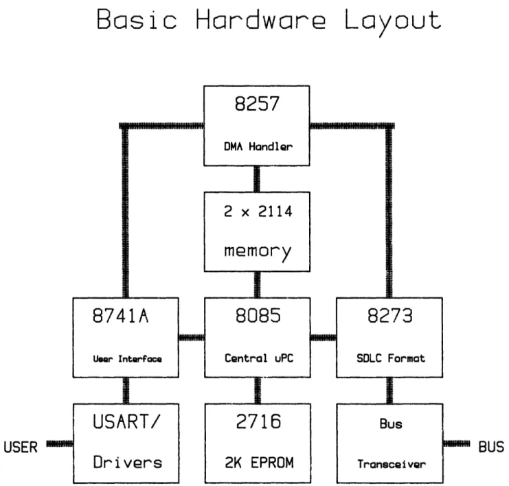
The 8741A is a member of the 8048 family of microprocessors, being a modified version of the 8748. The chief difference between the 8748 and the 8741A is that the external data/address bus on the 8748 is a data bus used only for communication with a master processor on the 8741A. Like the 8748, the 8741A has 1K of program memory and 64 bytes of RAM. Unlike the 8748, the 8741A can be configured to operate with a DMA handler. Combined with the capability of 16 pins of I/O and onboard timing, the 8741A is suited to almost any kind of interface. Perhaps the biggest advantage to the design of the prototype network is that by concentrating the user interface in the 8741A, the user interface may be changed by altering a single chip, without altering the basic operation of the network interface. The user interface, then, is a module consisting of the 8741A and its necessary line-driving or conversion peripherals. The basic hardware layout for the network is shown in Figure IV.l1, and the final assignment of functions is shown in Table IV.2.
C. Interconnection of Chips
The interconnection of chips involves not only the specification of wiring diagrams but the protocol for exchange of data between the basic functional blocks of the bus units. This protocol takes the form of establishing
Basic Hardwcre
La
yout
USER mm EMIEMHINMlI:II.._2 x 2114
memory
8085
Central uPC2716
2K EPROMFigure IV.1: Basic Hardware Layout
-35-8257
DMA Handler8741A
User Interfacei
8273
SDLC FormatUSART/
Dr
i
vers
Bus Transceiver h..Wm. BUS I VWWMMMMMH I m e aI
Table IV.2 Necessary Functions for Network Units
FUNCTION PERFORMED BY
Bus transceiver management 8273 Data input/output
Transceiver clock
Control line management
SDLC formatting 8273 Flag appending Bit stuffing CRC calculation CRC check Control code Destination addressing Sender addressing 8085 Address recognition* 8273 COUNT calculation 8085
Network receive buffering* 8273 to memory User input buffering* 8741A and memory Control message composition 8085
Data message* Acknowledgement* Token Initialize** User interface* Format stripping 8273 Conversion/translation 8741A Prompting 8741A Power-up procedure 8085
*indicates BIU function only **indicates CCU function only
-36-standard messages and format, and establishing priorities for interrupts and DMA channel usage. The first step in specification of the interconnection is to determine the control and data needs of each station component. Next, addresses must be stipulated for all necessary memory and I/O locations, forming the station's memory map. Finally, a rough flowchart is prepared, from which the actual software can be derived.
In general, each major component in the station will have the following: a chip select input used for enabling operation, address and data lines for transfer of data, a clock input or crystal input for onboard clock generation, registers for indication of status or commands, and a reset input which can be used to force the chip into a predefined state. Because the 8085 is designed always to be the central (or sole) processor, it does not have a chip select input. Operation of the 8085 may only be delayed by the HOLD input, used by the DMA handler in this design. Because of its central role, the 8085 has clock and reset outputs as well as inputs. These outputs can be routed to the various peripheral chips. Finally, its orientation is to send commands and read status, which is just the opposite of the other peripherals which send status and read commands. The clock for the 8085 is derived from a crystal input and the reset input is connected to a switch
in parallel with an RC network which will pull reset true shortly after power-up.
Some of the connection for the 8257 DMA handler has already been discussed; the 8257 shares the address and data lines of the 8085 by use of the 8085's HOLD input. In addition, the 8257 requires commands from the 8085 before any action may be taken. The mode register must be set to establish the activity of each of the four available DMA channels and the type of transfers to be made. Each
channel has a set of four registers which must be set, corresponding to two-byte values for starting address of the transfer and the number of bytes to be transferred. The higher order byte of the number to transfer register also contains two bits which indicate whether the transfer is written to or read from memory. Finally, a status register
is available for reading by the central processor. Of four possible channels, three are used in the prototype station design. Each channel has two control lines, DMA request (DRQ) and DMA acknowledgement (DACK), which are used to control transfer on an active channel. The peripheral sets DRQ to initiate transfer. When the DMA handler is ready with valid data (i.e. the handler has control of the data/address lines) it responds by setting DACK. The transfer is completed by normal operation of the read/write lines associated with the data/address lines. Assignment of channel numbers is not a trivial task; in the event of simultaneous request by two or more channels, service is granted by a priority scheme in which the lowest channel number has the highest priority. Thus channel 0 should be assigned to the peripheral least capable of waiting for memory access.
The 8273 SDLC chip is similar in format to the 8257, but requires more commands and provides a wider range of functions. In addition to command and status registers, the 8273 has a parameter register, needed for passing information about commands, and result registers, which provide information about the completion of the last command. The 8273 also provides interrupt outputs which signify the completion of transmission and reception. The commands used in the prototype design are Set Operating Mode, Set Serial I/O Mode, Selective Receive, Transmit Frame, and Abort Transmit. The two mode commands can be set once for all time at power-up. Each requires a byte to
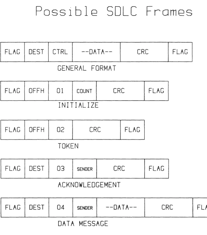
be sent to the command register and a byte to the parameter register. The parameter bytes are used to initiate buffering of address and control parameters, a frame preamble for synchronization, and NRZ data encoding. Selective Receive requires a command and four parameters. The first two parameters are the maximum message length and the second two are the match addresses (one is the station's unique address, the other is the network broadcast address, OFFH). In Selective Receive, a valid frame will not be saved unless the destination address is one of the match addresses. When a frame with the appropriate address is received, the 8273 saves the address and control bytes for the central processor and stores the message in memory through DMA. An interrupt is generated at completion of the reception, at which time the central processor must read the two saved bytes plus the Receive Result register before any new commands are given. Transmit Frame is similar; it requires a command and four parameters, the first two being the message length and the last two the destination address and control byte. An interrupt is generated at completion of transmission, at which time the Transmit Result register must be read. Abort Transmit is a one-byte command which terminates any transmission in process. Between any two transfers of command and parameter to the 8273, the status register must be checked to insure that the byte has been accepted. The control byte previously mentioned is not stipulated by the 8273, nor is it used by the chip for any decision-making. It is an eight-bit value which is forwarded to the central processor, making it ideal for the determination of message type. The convention used in the prototype network is that control code 01 represents an initialization message, and that the byte following the control code in the frame is the new value for COUNT.
Control code 02 is the token message; no additional data other than the CRC and flag follows the control code. Control code 03 is the acknowledgement message; the byte following the control code is the address of the station sending the acknowledgment. Control code 04 is for data messages; the first byte following the control is the sender's address, and a message of up to 255 bytes precedes the CRC and closing flag. The format for each of the four different types of messages is shown in Figure IV.2. The exchange of information between the 8741A and the 8085 is largely left undefined by the chips themselves. The 8741A has a data bus which is dedicated to interaction with a master processor. This bus is buffered and can be loaded at any time. Depending on the sense of an additional control line, the data exchanged is understood to be either data or command. For the purposes of the prototype network, there was a need for four distinct messages from 8085 to 8741A, and another four from 8741A to 8085. The four master-to-slave messages cover the cases when the destination does not respond to a message (code 01), when a message has been received from the network and is ready for forwarding to the user (code 02), when the user interface may proceed to compose a new message into memory (code 03), and when it is necessary for the user interface to wait for another command. In the first two cases, parameters are sent following the command: the no response code is followed by a byte corresponding to the address of the unit which did not respond, and the message received code is followed by a byte which is the length of the message to be forwarded.
The slave-to-master messages are similar, covering the cases when the user interface has completed composing a message to be sent (code 01), when DMA set-up is required for the start of a new message (code 02), when forwarding
Possib1
SDLE
Frames
FLAG DEST CTRL --DATA-- CRC FLAG
GENERAL FORMAT
FLAG OFFH 01 COUNT CRC FLAG
INITIALIZE
FLAG OFFH 02 CRC FLAG
TOKEN
FLAG DEST
03
SENDERCRC
FLAG
ACKNOWLEDGEMENT
FLAG DEST
04
SENDER -- DATA--CRC
FLAG
DATA MESSAGE
of a message to the user is completed (code 03), and when a system error requires discontinuation of the current composition process (04). Only the first command supplies any parameters to the 8085; in that case, a byte corresponding to the length of the message is followed by a byte for the destination of the message.
The 8741A is also required to operate some sort of peripheral for communicating with the user. For the prototype network, this peripheral was a Universal Synchronous/Asynchronous Receiver/Transmitter (USART), the Intel 8251. Like the 8273, the 8251 requires mode setting at power-up (7-bit ASCII encoding, asynchronous mode with odd parity, one start bit and one stop bit), and commands for receive and transmit functions. In addition, the user may require prompting during the composition of a message. A stipulation was made that the user would initiate a message by typing a linefeed (ASCII 10) and concluded a message by entering a dollar sign ($). After the dollar sign, the user must enter a two digit value for the destination of the address; the conversion of the address from ASCII to an actual number is handled by the 8741A. Two additional issues must be discussed before a full description of the hardware design can be given. First, the interrupt structure for the 8085 must be determined. Second, the algorithm for mapping the peripherals must be stipulated. The question of interrupt structure is one of assignment and priority. There is no reason forcing the use of an interrupt structure; all necessary information could be had by continuous monitoring of the status of the individual peripherals. In the interest of speed, however, interrupts are justified. The 8085 allows for three interrupts. Once set by some external source, an interrupt will be serviced following completion of the current instruction. The 8273's receive interrupt was given top
priority, followed by the interrupt output of the 8741A, and the 8273 transmit interrupt. This priority grew out of the faster network data rate and the 8741A's ability to store data on the short term. The transmit interrupt merely indicates availability of a status byte indicating successful transmission, and thus it can be serviced last in the case of conflicting requests.
The choice for address mapping is between so-called "memory-mapped I/O" and "I/O mapped I/O." [14] In memory-mapped I/O systems, there is no distinction made between memory and peripherals as data sources; each has a unique address and can be accessed by any of the memory access instructions. In I/O mapped I/O systems, memory and peripherals are regarded as separate entities; peripherals can only be accessed by use of IN and OUT instructions. The memory-mapped structure has the advantage of allowing more complex arithmetic and logical manipulations of data from peripherals, but requires slightly more time for simple transfers (13 clock cycles as opposed to 10). Because of the need for fast transfers, and the anticipation of little need for arithmetic manipulation of peripheral data, I/O mapped I/O was chosen. In this mapping scheme, each peripheral data source has its own address. An eight bit I/O port is used to manage the peripherals' chip select and control lines. The I/O address is the value the port must output to access a given peripheral. Since some peripherals may have several registers accessed by a set of control lines, it is possible for one peripheral to have several I/O addresses, each corresponding to one particular register. The memory map is shown in Table IV.3 and the I/O map is in Table IV.4. After an initial wire-wrapped version mysteriously failed to function and proved a near impossible problem in debugging, subsequent versions of the prototype network
were constructed on an SDK-85 microprocessor development board. This allowed easy access to memory and registers for analysis of bugs in development. As a result, the memory map starts at 0800H as opposed to the normal 0, because the development board provides program and memory space that cannot be overwritten. Another revision required was the change of the lowest priority interrupt, required by the development board for a keyboard management function. The 8273 transmit interrupt was disconnected and its function replaced by monitoring of the transmit status register.
The tables and figures that follow contain all necessary information for the actual interconnection and programming of the network stations. The basic circuitry is the same for the CCU and the BIU, with the exception that the CCU contains no user interface, and thus needs no 8741A nor its associated peripherals. The software of the two kinds of stations is similar; however, the CCU uses a general receive command with the 8273, in order that it may monitor all activity on the network. Appendix A details the method used for producing actual assembly language code from the details provided in this section.
-45-Table IV.3 Station Memory Map ADDRESS 0-07FFH 0800H-OFFFH 100OH-10FFH 110OH-135AH 135BH-13BFH 13COH-13FFH MEMORY CONTENTS
Monitor programs and memory (PROM) Main program memory (PROM)
Buffer for user interface input (RAM, 256 bytes) Buffer for network input (RAM, 603 bytes)
Scratchpad memory (RAM, 101 bytes) Program stack (RAM, 64 bytes)
Table IV.4 Station I/O Map
MNEMONIC IAODMA ITODMA IA1DMA IT1DMA IA2DMA IT2DMA IMSMDA I08273 I18273 008273 018273 I08741 I18741 RESIDENT
DMA: Channel 0 address register
Channel 0 terminal count register Channel 1 address register
Channel 1 terminal count register Channel 2 address register
Channel 2 terminal count register Mode setting register
8273: Command/Status register Parameter/Result register Transmit Result register
Receive Result register 8741: Data register Command register -44-ADDRESS 10H
llH
12H 13H 14H 15H 18H 40H 41H 42H 43H 80H 81HTable IV.5 8257 Specifications
Channel 0 (highest priority): 8273 Receive data Channel 1: 8273 Data for transmission
Channel 2: 8741 receive and transmit data Channel 3: (lowest priority): not used Clock input: from 8085 clock output Reset input: from 8085 reset output Mode byte: MSB Autoload
TC stop Extended write Rotate priority Enable Ch. 3 Enable Ch. 2 Enable Ch. 1 LSB Enable Ch. 0 (off) (off) (off) (off) (off) l=on
Commands: Mode set
Set starting address (each channel) Set terminal count (each channel)
-46-Table IV.6 8273 Specifications
Receiver interrupt (RxInt): to 8085 RST 7.5 Transmitter interrupt (TxInt): not used
Receiver DMA (RxDRQ and RxDACK): to 8257 Channel 0 Transmitter DMA (TxDRQ and TxDACK): to 8257 Channel 1 Clock input: from 8085 clock output
Reset input: from 8085 reset output
Modem control lines (RTS, CTS, CD): to bus transceiver Transmit Clock: from clock generator
Modes:
One bit delay (off) Command 64H Data transfer mode (off) Command 57H Operating mode byte
MSB HDLC mode (off) l=on EOP interrupt (off)
Early Tx int (off) Buffered mode (on) Preframe sync (on)
Flag stream (off) Command 91H Parameter 06H Commands:
Selective Receive (for BIU only) Command C1H
Parameter <Buffer size (L)> Parameter <Buffer size (H)> Parameter <Match address#l> Parameter <Match address#2> General Receive (for CCU only)
Command COH
Parameter <Buffer size (L)> Parameter <Buffer size (H)> Transmit Frame
Command C8H
Parameter <number of bytes (L)> Parameter <number of bytes (H)> Parameter <destination address> Parameter <control code>
Abort transmit Command CCH Abort receive
Table IV.7 8741 Specifications
Data Bus (DO-D7): to 8085 Address/data bus Chip select: tied low
Clock input: 6.144 MHz crystal Reset input: 8085 reset output
I/O Port 1: 8251 output lines
I/O Port 2: P10-P12 to 8251 control lines P24 (OBF) to 8085 RST 6.5 P26, P27 to DMA Channel 2
Tests (TO and T1): to 8251 RxRDY and TxRDY lines Modes: none
Commands from 8085:
No response Command 01H
Message for user
Begin DMA from user Hold: no DMA
Messages to 8085:
User message complete
Request DMA
Transfer to user done Abort message buffer
Parameter <station address> Command 02H
Parameter <message length> Command 03H
Command 04H
Status=01H
Parameter <message length>
Parameter <destination address> Status=02H
Status=03H Status=04H
-48-Table IV.8 8251 Specifications I/O lines (DO-D7): to 8741A Port 1 Control lines: from 8741A Port 2
Data received interrupt (RxRDY): to 8741A Test 0 Transmitter ready interrupt: to 8741A Test 1 Chip select: tied low
Clock input: from 8085 clock output Reset output: from 8085 reset output Transmit data (TxD): to user
Receive data (RxD): from user
Transmit clock (TxC): from clock generator
Receive clock (RxC): none (asynchronous operation) Mode Byte: Stop bits: 1 D7=0 D6=1 Parity: odd D5=0 Enable parity D4=1 6-bit characters D3=1 D2=0 Baud rate factor: 16 D1=l
D0=1 Mode byte=5BH Command byte:
Hunt mode (off) 0 MSB Internal reset (off) 0
Request to send (off) 0
Error reset (off) 0
Send break (off) 0
Receive enable
Data Terminal Ready (off) 0 Transmit enable
-49-Table IV.9 8085 Specifications
Interrupts:
RST 7.5 8273 Receive interrupt
RST 6.5 8741A Output Buffer Full flag RST 5.5 SDK-85 kit board use
Reset: Debounced switch and RC network (for power-up) Clock: Derived from 6.144 MHz crystal
I/O Mapping: I/O mapped (see memory and I/O maps) Program memory: 2K bytes (Intel 2716)
Working memory: 1K bytes (two Intel 2114)
-50-DETAILED FLOWCHARTS
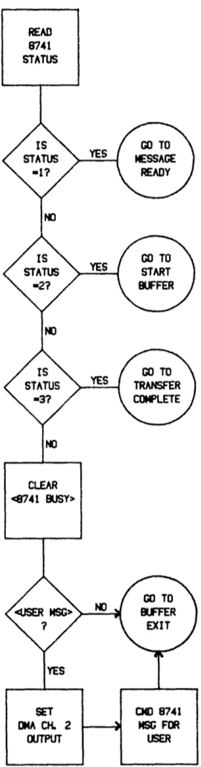
The next 21 pages contain the detailed flowcharts for the BIU, CCU, and 8741. They are the basis for the assembly language programming of the network units. In essence, they are an amplification of the flowcharts which appear in Section III. The flowcharts contained here should be consulted only for information regarding implementation of function, while those of Section III provide the clearest picture of the network operation.
BIU Flowchart: Power-up/Reset
Figure IV.3.1 Detailed Flowchart: BIU
-52-BIU: On RST 6.5 (8741 Interrupt)
Figure IV.3.2 Detailed Flowchart: BIU
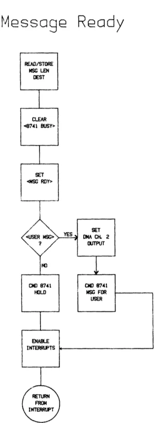
-53-BIU: Messoage Ready
Figure IV.3.3 Detailed Flowchart: BIU
-54-BIU: Start
Buffer
Figure IV.3.4 Detailed Flowchart: BIU
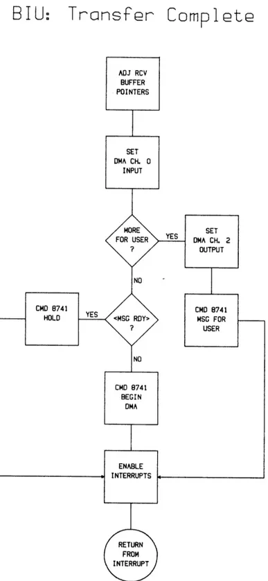
BIU:
Transfer
Comp1
t
Figure IV.3.4 Detailed Flowchart: BIU
-56-BIU: On RST
7.5
(8273
RxInt)
Figure IV.3.5 Detailed Flowchart: BIU
-57-BI
U:
Receive Error
Figure IV.3.6 Detailed Flowchart: BIU
-58-BITU
Initialize
Figure IV.3.7 Detailed Flowchart: BIU
-59-BIU
I ncr
Token
BIU:
Send Message
B I U
Ack
Recei
ved
Figure IV.3.10 Detailed Flowchart: BIU
-62-BIU: Message Received
Figure IV.3.11 Detailed Flowchart: BIU
-63-CCU Flowchart: Power-up/Reset
Figure IV.4.1 Detailed Flowchart: CCU
-64-CCU: Waiting
Figure IV.4.2 Detailed Flowchart: CCU
-65-CCU: On RST 7.5 (8273 RxInt)
CCU:
Token Received
8741 Flowchart: Power-up/Reset
Figure IV.5.1 Detailed Flowchart: 8741
-68-8741:
Beg
i
n Message
Figure IV.5.2 Detailed Flowchart: 8741
-69-8741:
Get Command
Figure IV.5.3 Detailed Flowchart: 8741
-70-8741:
No
Response
Figure IV.5.4 Detailed Flowchart: 8741
-71-8741: Output
Message
V. Analysis of the Prototype Network
A. Definition of Performance Parameters
After a prototype network of four stations had been successfully brought to operation, a quantitative measure of the performance of the system was desired. Primarily, this measure concerned the data-handling capability of the network (a discussion of reliability of the network is contained in the first part of Section VII), which may be characterized by three parameters: access delay, efficiency, and throughput. Part A of this section concludes with a definition of these parameters, part B is devoted to the development of a mathematical model of the network operation, and part C uses this model to project values for the three parameters.
In order to accurately describe the network, the general definitions of the performance parameters must be tailored to the network's unique features. These parameters may not be directly measurable, but once determined, they should give an accurate description of regular operation. For instance, because of the network transparency requirement, the user is not aware of any access delay time. However, if a steady stream of data is fed to a network interface, the delay will have a noticeable effect. The access delay is defined as the time from user completion of a message (including destination address) to the time at which that message is actually transmitted on the network medium. Because of the independent operation of the user and bus interfaces, the access delay is not a constant quantity (consider the difference in delay for the cases where the user completes input of a message just before the station's token COUNT is reached, as opposed to just after). For this reason, coupled with the negative nature of delay, the access delay is considered for the