Design of a Mechanical System for Tillage Tool
Depth Control on Small Farm Tractor
by Elizabeth Porter
Submitted to the
Department of Mechanical Engineering
in Partial Fulfillment of the Requirements for the Degree of
Bachelor of Science in Mechanical Engineering
at the
Massachusetts Institute of Technology
June 2017
2017 Massachusetts Institute of Technology. All rights reserved.
Signature of Author:
Certified by:
Signature redacted_
Department of Mechanical EngineeringMay 12, 2017
_Signature redacted
Amos Winter Assistant Profes r of Mechanical Engineering Thesis SupervisorSignature redacted
Accepted by: MASSALCHUSE S INTITUTE OF TECHNOLOGQYJUL
25Z017
LIBRARIES
Rohit Karnik Associate Professor of Mechanical Engineering Undergraduate OfficerDesign of a Mechanical System for Tillage Tool Depth Control on a Small Farm Tractor
by Elizabeth Porter
Submitted to the Department of Mechanical Engineering on May 12, 2017 in Partial Fulfillment of the
Requirements for the Degree of
Bachelor of Science in Mechanical Engineering
Abstract
Tractor implements increase the risk of injury by destabilizing the tractor, and therefore they must be designed with caution and mechanical integrity. Tillage tool attachment systems must be designed to determine a tool's maximum depth into the soil and withstand the resulting forces from the soil. The following paper presents a design for an attachment system that incorporates a self-locking rack and pinion jack, load-bearing sliding surfaces, and rack clamp that is used to secure the cultivator sweep. The design is evaluated for deformation and deflection at the maximum theoretical loads using Finite Element Analysis. The design
successfully minimizes deflection, but exhibits stresses higher than the material yield stress in a small area. After slight modifications to the bar attachment structure in a future design iteration, the tillage tool design will be ready to test in the field.
Thesis Supervisor: Amos Winter
Acknowledgements
I would like to thank all those who helped make this thesis possible. Thank you to Professor Amos Winter for the opportunity to work on this project. To Guillermo Diaz
Lankenau, thank you for the weekly feedback and design suggestions. I really appreciate your enthusiasm and support throughout the course of the project. The two of you have been
invaluable resources to me and have provide me with much needed guidance and direction over the past term. I have really enjoyed working with you both and with this project for the past few months.
Table of Contents
Chapter 1: Introduction 10
1.1. Dangers of Agriculture 10
1.2. Mechanization Challenges for Small Farmers 10
1.3. Tilling 11
1.4. Motivation for the Project 11
Chapter 2: Design 13
2.1. Design Requirements 13
2.2. Sub-System Review 15
2.2.1. Rack and Pinion Jack 15
2.2.2. Rack Support Structure and Frame Attachment 17
2.2.3. Rack Clamp 19
2.3. Integrating the Tool, the User, and the Vehicle 21
2.3.1. Placement 21
2.3.2. Spacing 21
2.3.3. User Interaction 21
2.4. Intended Use of Design 22
Chapter 3: Evaluation 23
3.1. Testing and Results 26
3.1.1. Mass 26
3.1.2. Soil Loading 27
3.2. Mechanical Assessment of the Design 30
3.2.1. Strength 30
3.2.2. Weaknesses 30
3.3. Future Work 31
List of Figures and Tables
Figure 1-1: Figure 2-1: Figure 2-2: Figure 2-3: Figure 2-4: Figure 2-5: Figure 2-6: Figure 2-7: Figure 2-8: Figure 2-9: Figure 2-10: Figure 2-11: Figure 3-1: Figure 3-2: Table 3-1: Table 3-2: Figure 3-3: Table 3-3: Figure 3-4. Table 3-4: Figure 3-5. Cultivator sweeps.Three major components of the tillage tool. Soil forces acting at the center of pressure. Rack and pinion jack.
Welded plate for jack attachment. Reaction forces on the rack. Shaft to bearing ratio. Bearing model.
Bar angles relative to the bearing. Tube clamp.
Cultivator shank. Rack clamp.
Computer model of the tillage tool raising system. Fixed model points in the simulation.
Design requirements and specifications. Bill of materials and mass.
Pressure forces on the cultivator sweep model. Static study results for test maximum loads. Static study results for test maximum loads. Static study results for theoretical maximum loads. Static study results for test maximum loads.
11 13 14 15 15 16 17 18 18 19 19 20 23 24 25 26 27 28 28 29 29
Chapter 1
Introduction
1.1 Dangers of Agriculture
Agriculture is one of the most dangerous industries in the world [1]. Long hours, hazardous machinery, and tasks that deal with heavy loads result in thousands of injuries and hundreds of deaths per year. A study performed by the Canadian Agricultural Injury Reporting division showed that 70% of agricultural accidents are caused by machinery, and of these
machinery accidents 35% involve a tractor [2]. Engine-powered tractors have existed since 1868 [3], and continue to be a fundamental tool for the agricultural industry. However, tractors have a history of danger and risk. The National Agricultural Safety Database notes that tractors are especially dangerous when they have attachments such as heavy loads or pieces of agricultural equipment [4]. Attachments greatly increase the risk of injury by decreasing the stability of the tractor [5]. This instability is caused by a difference in the loads on the front and back wheels of the tractor, which leads to lift at the front or back of the vehicle. When the wheels lift enough to cause the tractor to tip, this is called rollover. 46% of agricultural deaths can be attributed to rollovers, run overs, and entanglements with a tractor [5].
1.2 Mechanization Challenges for Small Farmers in Developing Countries
On small farms in developing countries, animal power is the most viable alternative to mechanical power as a source of agricultural energy for farm chores [6]. One of the obstacles to farm tractor adoption is their large turning radius. The turning radius of an animal or tractor is important when working in crop rows. Space must be left at the end of a crop row in order to allow the animal or tractor to turn and traverse the adjacent row of crops. If crops block the turning path of the animal or tractor, it will crush the crops. A small turning radius allows the farmers to utilize the majority of their field for crops as opposed to turning space. Compared to
1.3 Tilling
Tilling is a farming chore where one turns over soil in order to break it up or mix it with amendments. Breaking up the soil separates compact soil into finer chunks, and amending the soil involves mixing organic matter with the soil [7]. Both processes produce a favorable environment for seed growth. Tilling requires the use of a cultivator, a tool with a sharp point that pierces the soil and drags through it linearly [8]. A cultivator sweep is a type of cultivator that minimizes soil disturbance and provides a clean cut of the soil with long, sweeping edges
[8].
a) b)
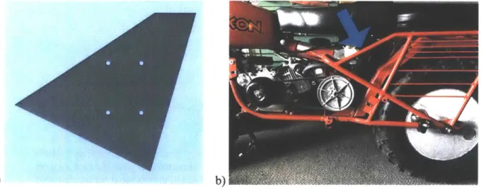
Figure 1-1. Cultivator sweeps. Image a) presents a small cultivator sweep with a 4-inch long wingspan. Image b) presents a larger cultivator sweep with a 16-inch long wingspan.
1.4 Motivation for this Project
The MIT GEAR Lab is creating an alternative to conventional small tractors and animals for soil working and other farm chores for small farms in India. As part of development, an all-wheel-drive motorcycle "test mule" is being created. The motorcycle's tractive and steering behavior will be evaluated in field tests to better understand performance of unconventional farm
"tractor" layouts. In order to perform the necessary operations on the soil during field testing, the motorcycle must be properly equipped for tilling. Existing tillage systems are designed to fit on a tractor, and are not compatible with the frame of a motorcycle. Therefore, a new tillage mounting
The potential pitfalls of the addition of tractor implements motivate an in-depth study of the effect and strength of the implement prior to its creation. The tool must be checked for
mechanical integrity. This includes proper placement on the tractor, minimal mass, appropriate spacing with respect to other implements, and robustness. In addition to these factors, ease of use and ease of installation should also factor in to the design.
Chapter 2
Design
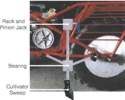
The tillage tool implement raises and lowers the cultivator sweep through the soil. The vertical motion of the sweep results from turning a hand crank that is located at the top of the implement. The hand crank belongs to a rack and pinion jack. As the crank rotates, the rack translates vertically. A static, rectangular bearing surrounds the rack below the crank. The bearing attaches to the frame of the vehicle using bars and frame clamps. At the end of the rack, the cultivator sweep rigidly attaches to the rack through a rack clamp.
Rack and G
Pinion Jack
Bearing
Cultivator. Sweep
Figure 2-1. Depiction of the three major components in the tillage tool system in the
approximate locations that they would attach to the vehicle frame.
2.1 Design Requirements
In order to be an effective and safe implement, the tillage tool attachment mechanism must meet certain basic design requirements and specifications.
The tool must withstand the reaction force of the soil. The soil reaction force can be separated into three components (see Figure 2-2), all of which act on the center of pressure of the tool. The tool should be designed to withstand high loads. There are two separate specifications that define the concept of a maximum load. The anticipated maximum loading during testing of the prototype in each of the three directions is 3000 N along the x axis, 1500 N along the z axis,
and 750 N along the y axis. Ideally, the structure should also be able to handle the maximum load that would result from collision with an obstacle. The predicted loads for this extreme case are 5000 N along the x axis, 2500 N along the z axis, and 1250 N along the y axis.
s9 F soil, Y
Center of F soil, X
Pressure
z
F so,
Figure 2-2. Three soil reaction forces acting at the center of pressure. The directions of vehicle travel and of gravitational forces are noted in the boxed area.
The placement of the tillage tool relative to the vehicle frame must be adjustable in the x, y, and z directions. Adjustment in the z axis should be available while the vehicle is in use. The attachment system should be able to move the tillage tool high enough above the soil surface to avoid obstacles while the farming vehicle is traveling and not working the soil. These obstacles could include large rocks or roadway speed bumps. The tillage tool must be able to lower 8" below the soil surface. This is the maximum depth at which field tests will be performed. Adjustment in the x and y directions should be available when the farming vehicle is not in use. This adjustment is necessary for increasing the test versatility of the test mule vehicle. Moving the tool in these directions will allow for testing of the placement of the tool which yields the most stable vehicle configuration.
2.2 Sub-System Review
2.2.1 Rack and Pinion Jack
The self-locking rack and pinion jack is the main component of the tillage tool. The stainless steel jack comes from an industry distributor called Haacon. The total rack length is
1205 millimeters, and the travel distance is 1000 millimeters. It weighs 7.7 kg, and can lift objects weighing up to 4900 N. The back plate of the jack allows it to mount to any flat surface. In order to attach to the farming vehicle, a metal plate with four holes will be welded to the frame of the vehicle. The jack can securely bolt to the plate.
Figure 2-3. Rack and pinion jack from Haacon industry.
a)
Figure 2-4. a) A model of the plate that is to be welded to the frame of the farming vehicle.
b) The side of the farming vehicle. The frame is composed of red bars with circular cross
sections. In order to mount the jack, the plate will be welded to the area indicated.
The crank handle attaches to a worm gear which also turns the pinion in the rack and pinion jack. The gear ratio between the worm gear and the pinion is 20:1, so the jack can lift a very heavy load while only requiring a small input force. The worm gear also makes the jack self-locking, ensuring that the rack does not slip unless the crank is turned.
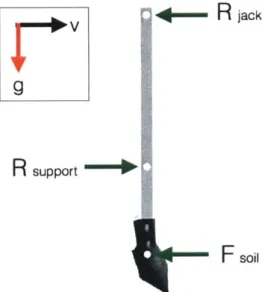
Typically, rack and pinion jacks are only loaded in the axial direction. They are not designed to accommodate forces that run perpendicular to the rack; the jack acts as a very long, very thin cantilevered beam in the presence of radial forces (see Figure 2-5). In order to augment the radial loading capability of the rack, the area moment of inertia of the rack must be increased. In this implement, a rectangular steel reinforcement increases the cross-section of the rack from 20 millimeters by 30 millimeters to 30 millimeters by 60 millimeters. This reinforcement is welded to the rack. In addition to increasing the cross section of the beam, an additional load-bearing slip surface helps to support the radial loads on the rack. The following section discusses the design of the rack support structure.
r.EER
jack9
R
supportF
soilFigure 2-5. The rack acts as a cantilevered beam which is fixed at the topmost point where it connects to the jack. Reaction forces on this beam come from the jack, the rack support structure, and the soil. The directions of vehicle travel and of gravitational forces are noted in the boxed area.
2.2.2 Rack Support Structure and Frame Attachment
A three-inch tall, low-carbon steel casing wraps around three sides of the rack. Thin delrin sheets line the inside of the casing to decrease the friction between the rack and the bearing. The bottom of the casing sits four inches below the lowest point of the vehicle frame. This is the minimum height from the ground that will allow reasonable clearance over obstacles that the vehicle might traverse, such as rocks. Having a low casing minimizes the ratio of LI to L2 (see Figure 2-6). Minimizing this ratio also minimizes the forces that the bearing and the
mounting plate experience due to the forces on the cultivator sweep.
Figure 2-6. The bearing sits four inches below the lowest point on the vehicle frame to lower for minimum ground clearance. L1 is the distance from the center of the rack and
pinion jack to the center of the bearing, and L2 is the distance from the center of the bearing
to the center of pressure of the cultivator sweep.
The bearing, as shown in Figure 2-7, only supports three sides of the rack. The open side faces the front of the vehicle. The open face allows the rack clamp that holds the cultivator sweep to pass through the bearing, as shown in Figure 2-7b. The back wall of the bearing is effected most during use, and any forces that would push the rack towards the open side of the bearing would be small. In order to account for these small forces, a pin can be used to provide a small reaction force. The pin has a quick release button that allows for easy removal when the user wishes to raise the cultivator sweep.
Rack
clamp
a) b)
Figure 2-7. a) The bearing has three sides, and the open side faces the front of the vehicle. A mounting plate interfaces between the bearing and the two bars. The pin provides a small reaction force in the case that the rack is pushed towards the front of the vehicle. b) The
rack clamp can slide through the bearing because the bearing has an open face.
The bearing attaches to a low carbon steel plate which serves as an interface between the bar extrusions and the bearing. The hollow bar extrusions have square cross sections of 40 millimeters with walls that are 2 millimeters thick. Figure 2-8 shows the specific length, angle, and orientation of the bars relative to the interface plate.
7"9
1 "
24.2
12.4*
Figure 2-8. Structure diagram showing the lengths and angles of the bar extrusion relative to the bearing.
Each bar extrusion connects to the frame of the vehicle using tube clamps. The tube clamps secure to the cylindrical tubes of the vehicle frame, and a bolt connects the tube clamp to the bar extrusion. In order to prevent the bar extrusion from deforming under the pressure of the
Figure 2-9. Tube clamp that is used to attach the tillage tool bars to the frame of the vehicle.
2.2.3 Rack Clamp
The tillage tool attaches to the rack through the use of a rack clamp and the foot of a cultivator shank (see Figure 2-10). The cultivator foot allows for the attachment of a wide range of cultivator sweeps. The tillage tool bolts to the top of the foot. Each tillage tool that will be used for testing - regardless of its wingspan - has the same size holes to interface with the foot.
I.'
b) a)
Figure 2-10. a) A cultivator shank, purchased from Agri Supply. This cultivator shank is able to have sweeps from 4 to 30 inches used on it. b) The foot of the cultivator shank was removed in order preserve the interface between the cultivator sweeps, but minimize the added mass of the other components in the cultivator shank.
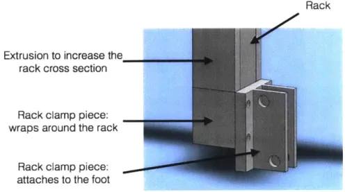
The rack clamp breaks into two pieces that fit around the rack. When the bolts tighten, the clamp tightens around the rack. One of the clamp pieces also has holes that interface with the cultivator shank foot.
Rack
Extrusion to increase the rack cross section
Rack clamp piece: wraps around the rack
Rack clamp piece: attaches to the foot
Figure 2-11. Rack clamp that wraps around the rack and connects to the foot of the cultivator shank. Above the rack clamp, the reinforcement used to increase the cross section of the rack is welded to the rack.
2.3 Integrating the Tool, the User, and the Vehicle
2.3.1 Placement
As the user operates the vehicle, the stability of the vehicle is critical. The location of the tillage tool will add a significant amount of load at the center of pressure of the tool. This load will also effect the wheels of the vehicle. In order to decrease the effect of the additional load on the wheels, the tillage tool is placed at the approximate center between the two wheels. This
distributes the load evenly to the wheels, thereby allowing for better traction and a reduced chance of rollover.
The location of the tool is offset approximately 15 inches behind the foot pedal of the vehicle. This separation of the tool and the user is important in order to reduce the likelihood of
implement and user entanglement and resulting injury.
The tool will be located on the left side of the vehicle, so the user can use their left hand to turn the crank. Their right hand will be used to control the accelerator of the vehicle, which is
located on the right handlebar, as is the convention for motorcycles. The outrigger wheel of the vehicle, which assists in vehicle stabilization, is also going to be located on the left side of the vehicle. This will help counteract any destabilization of the vehicle caused by the soil forces on the tillage tool.
2.3.2 Spacing
The frame of the pre-existing vehicle played a large role in determining the shape and size of the tool. The tool had to fit in a relatively narrow space between the foot pedal of the vehicle and the outrigger wheel that extends over the rear wheel on the vehicle. Because of this narrow space, it made sense to design a structure that was tall and skinny, and did not extend in the x direction along the frame of the bike.
2.3.3 User Interaction
In order to actuate the tool, the user inputs a low force. This is an intentional design that results from the gear ratio of the rack and pinion jack. A low input force requirement preserves the user's strength for other farm chores and careful operation of their vehicle. Additionally, the
operation of the tool only requires one step. The user does not need to worry about fixing the motion of the rack; the built in worm gear which allows the rack to self-lock.
2.4 Intended Use of the Design
In order to operate the tillage tool, the tool must first be installed onto the vehicle. This requires the attachment of the tube clamps to the frame of the vehicle, and the attachment of the rack and pinion jack to the vehicle. A tillage tool can be mounted to the attachment system by bolting the tillage tool to the cultivator foot, and attaching the foot to the rack using the rack clamp. To lower the tillage tool into the soil, the user turns the handle of the rack and pinion jack. This actuates the rack, and the tillage tool translates into the soil. After the extension of the
rack to the desired height, the user should insert the removable pin into the bearing and drive the vehicle forward to begin tilling. When the user reaches the end of a crop row and wishes to turn the vehicle, they should raise the cultivator sweep out of the ground. The cultivator sweep should be high enough above the ground to clear any obstacles that the vehicle might encounter while turning.
When the user completes the farm chores, the cultivator sweep can be raised to its highest position for maximum ground clearance. The pin in the bearing should be removed so the
Chapter 3
Evaluation
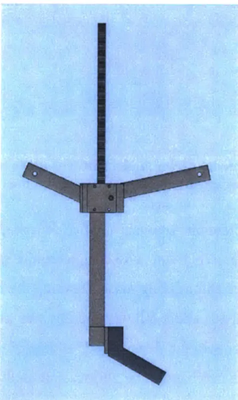
Computer simulations and modeling allowed for the simulated testing of the design. The computerized model did not include the vehicle frame nor the pinion and worm gear of the rack and pinion jack. As seen in Figure 3-1, the model contains the rack, the rack cross section extension, the bearing, the bar extrusions, the plate that interfaces between the bearing and the bars, the rack clamp, and a simplified model of the cultivator sweep.
Figure 3-1. The computer model of the tillage tool raising system.
The ends of the bar extrusions are fixed in the model, which reflects the assumption that the bar and the vehicle frame are rigidly joined by the tube clamp. The rack extends to where the interface between the rack and the gear would be. At this height of the rack, the model is fixed in
space. This reflects the assumption that the rack and pinion gears will rigidly hold the loads of the system. Both of these model assumptions are shown in Figure 3-2.
Figure 3-2. The computer model of the implement. The green arrows point to the three locations on the implement where the object was considered to be fixed.
Using this model, Finite Element Analysis verified four major specifications, and Mass Analysis verified the fifth major specification. The design requirements for evaluation (which are
summarized in Table 3-1) included minimizing mass, ensuring the handling of soil loads, and minimizing deflection. Mass Analysis and a bill of materials was used to evaluate the system mass. Mass Analysis takes into account the density and volume of the components within the model. To evaluate if the structure can handle the various soil loads, a static study in Solidworks analyzed the von Mises stresses in the various components as compared to the yield strength of the materials. Deflection of the cultivator sweeps tip was determined with a static study in Solidworks that analyzes the deflection of the part in response to the applied load based on the stresses and yield strength of the material.
stress within this volume. The average comes from averaging the stress at eight unique nodes on the mesh of the model.
Table 3-1. Summary of the design requirements and target specifications. Each of the soil loads has two specifications: the larger specification represents the theoretical maximum force applied, and the smaller specification represents the largest anticipated force that will be encountered in testing.
Design Requirement Target Specification Method of Verification
Minimize the mass < 30 kg Mass Analysis
X axis soil loads 5000 N / 3000 N FEA
Y axis soil loads 2500 N / 1500 N FEA
Z axis soil loads 1250 N / 750 N FEA
3.1 Testing and Results
3.1.1 Mass
Using the Mass Analysis on Solidworks, the mass of the rack cross section extension, the bearing, the bar extrusions, the plate that interfaces between the bearing and the bars, and the
rack clamp is 7.75 kg. The bill of materials (see Table 3-2) helps identify the remaining mass of the system, which is 8.23 kg. This creates a combined total of 15.98 kg, which is less than the specification maximum of 30 kg.
Table 3-2. Bill of materials and the corresponding masses.
Quantity Material Mass/Item [g] Total Mass [g] 20 1/4"-20 bolt, 1" length 8.14 162.80 20 1/4"-20 nut 3.55 71.08 2 7/16"-20 bolt, 1" length 27.21 54.42 2 7/16"-20 nut 10.15 20.29 2 7/16" washer 5.65 11.30 2 3/8"-16 bolt, 1" length 19.59 39.18 2 3/8-16" nut 7.71 15.42 2 3/8" washer 1.61 3.22
1 Quick release pin 150.00 150.00
1 Rack and pinion jack 7700.00 7700.00
3.1.2 Soil Loading
The computer simulations for the load caused by the soil assume that the force acts as a pressure across the top face of the cultivator sweep. The pressure distributes uniformly across the face, as seen in Figure 3-3. Two simulations verified the performance of the model under the theoretical maximum loads and the anticipated maximum loads.
Y
Figure 3-3. The structure is an approximate representation of the average size cultivator sweep that will be attached to the structure during testing. The purple arrows show the pressure forces. The forces apply to two faces. The top face of the cultivator sweep model undergoes pressure forces along the z and x axes, and the side face of the cultivator sweep model undergoes the pressure forces along the y axis.
In the first simulation, the model experiences forces at the anticipated maximums for field testing. The anticipated field-testing maximums for z axis, x axis, and y axis pressure loads are 1500 N, 3000 N, and 750 N respectively. Under these loads, the model results are
summarized in Table 3-3. The region of largest deformation occurred on the shorter bar extrusion close to where the bar meets the bearing. This region has an approximate volume of 0.59 cubic centimeters, and the average Von Mises stress in this area is 260.7 MPa. The yield strength of this region is 250 MPa. The maximum deflection of the cultivator sweep occurred at the tip of the cultivator sweep, and the distance of deflection was 3.796 mm.
Table 3-3. Summary forces applied in the respectively.
of the results from the static Solidworks study with three pressure z axis, y axis, and x axis loads of 1500 N, 3000 N, and 750 N
von Mises (N/m 2) 2500e+008 2.292e+00W S2,083e+008 .1.875e+008 1.66?e+008 1.250e+008 1.042e+008
I
1333*e407 .2soe+007 ']1 67e+007 2.083I+007 0.000e+000 URES trmm) 1.000e+0w1R.167e+000
.2333**000 -6.667e+OOO 5.933eOOO 5.000e+000 4.167e+000 3.333e+000 2.500e+000 1.667e 9OO 8333e-001 O.zooe+000 '4 b)Figure 3-3. a) Colored representation of the von Mises stresses in the implement. The color scale ranges from 0 MPa (blue) to 250 MPa (red), which is the yield stress of low carbon steel. b) Colored representation of the deflection of the implement. The color scale ranges from 0 mm (blue) to 10 mm (red), which is half of the maximum allowable deflection.
Region of Highest Stress Concentration Maximum Deflection
Volume Average von Mises Stress [mm]
[cm3] [MPa]
0.59 260.7 3.796
In the second simulation, the model experiences forces at the extreme maximums as defined by the theoretical maximum that the structure should be able to take. The theoretical maximums for z axis, y axis, and x axis pressure loads are 2500 N, 5000 N, and 1250 N respectively. Under these loads, the model results are summarized in Table 3-4.
Table 3-4. Summary
forces applied in the respectively.
of the results from the static Solidworks study with three pressure z axis, y axis, and x axis loads of 2500 N, 5000 N, and 1250 N
von Miles (N/m^2) 2500e+00B1 2292e+008 .2.083e+008 1.875e+008 1.667e+008 1250e+008 1.042e+008 8333e*007 6250e+0O7 4.1674t+007 2,03e-007 0.000e+000 LIES (mm) 1.000e+001 9.67e+000 8333e4000 7500e+000 S6.667e+000 5S33e+000 5.000e+000 4.167e+000 3.333e+000 2500e.O00 1.667e00 8333e-001 0.000e.000 b)
Figure 3-4. a) Colored representation of the von Mises stresses in the implement. The color scale ranges from 0 MPa (blue) to 250 MPa (red), which is the yield stress of low carbon steel. b) Colored representation of the deflection of the implement. The color scale ranges from 0 mm (blue) to 10 mm (red), which is half of the maximum allowable deflection.
Region of Highest Stress Concentration Maximum Deflection
Volume Average von Mises Stress [mm]
[cm3] [MPa]
0.87 263.9 4.657
3.2 Mechanical Assessment of the Design
3.2.1 Weaknesses
The component with the highest potential for deformation under soil loads is the bar extrusion. The deformation impacts an approximate volume of 0.87 cm3 at the maximum
expected loads, which could result in a failure of the design if the system faces the maximum loads multiple times. In order to ensure that the system is fully prepared to repeatedly cycle through maximum loading, there should be further experimentation on the number of bar
extrusions, the design and orientation of the resulting truss structure, and the necessary thickness of the bar extrusions. More specifically, based on the results of the above testing and the primary locations of material failure, the first parameters that should be investigated are the angles of the bars that connect the bearing to the vehicle frame. These angles should be optimized to reduce
the load on the bars, and therefore minimize material deformation.
3.2.2 Strengths
The bearing and increased cross section of the bar both serve to minimize the deflection of the tip of the cultivator sweep. The maximum anticipated tip deflection is approximately one-quarter of the maximum specification. If the tip deflects to the maximum amount, a high drag force pulls the cultivator sweep downward. This can cause a highly damaging addition of force that could result in deformation and failure. Therefore, it is important that the design is cautious towards this specification, and undershoots this maximum by a factor of four.
Additionally, due to the design of the rack and pinion jack, the rack can actuate under high vertical load. The rack and pinion jack is rated for approximately 4900 N of force in the axial direction; it is a very robust system along the axis of the rack.
3.3 Future Work
The primary drawback with the tillage tool design is the inability to adjust the location of the tool in the x and y directions. Off-line adjustments of these coordinates would help to test and optimize the loading of the wheels in order to maximize the stability of the set-up. The current system should be adapted to include the ability to make these adjustments.
Actuating the system requires little force, but the actuation occurs slowly. For every turn of the crank, the rack lifts 9.4 mm. This means that in order to raise the cultivator shaft from the low point under the soil to the high point above the bearing, the user must turn the crank 54 times. Ideally, a second version of the system would have a higher lift to crank ratio, or a method of electrically actuating the crank. This will minimize the fatigue of the user, and maximize the ease of use.
Another potential system failure is clogging due to dirt or other debris, especially around the bearing. It is possible that such debris could affect the movement of the rack through the bearing. This effect should be tested, and in the case that clogging causes problems with the actuation of the system, there should be a method designed to either unclog the system or prevent the system from clogging.
Although cost does not affect the success of this prototype, the ultimate vehicle project strives for low-cost parts in order to lower the cost of the product. The vehicle must be listed at a price that can compete with the price of livestock, or else cost an amount that scales with the value added to the product from the perspective of the user. The rack and pinion jack costs around $400, and very few retailers sell these systems. While the commercial rack and pinion jack will work for testing, there should be an alternate, cheaper way to create and assemble the rack and pinion jack.
Chapter 4
Summary and Conclusion
The design of the tillage tool attachment system has three major components: the rack and pinion jack, the bearing, and the rack clamp. The three parts work together to raise, lower, and hold the cultivator sweep. The tool is designed to withstand loads from the soil in the z, y, and x directions. At the theoretical load maximum, the tip of the cultivator sweep deforms much less than the maximum specification. One of the bars that connects the bearing to the vehicle frame deforms in a small area; this deformation will not endanger the user as it is very small. Moving forward, the method of attaching the bearing to the vehicle frame could be redesigned to ensure that the system does not fail under repeatedly large soil loads.
The primary purpose of testing the computer model of the system design was to ensure that the design, if and when it is built, can operate safely and effectively under high loading conditions. The existing tool cannot currently guarantee safety and effectiveness under the maximum loads, but after the suggested experimentation and modification, the tool will be ready
Bibliography
[1] Allen, Will. "Agriculture Is One of the Most Polluting and Dangerous Industries." Alternet. Chelsea Green Publishing, 11 May 2009. Web. 10 May 2017.
[2] Canadian Agricultural Injury Reporting. "Agricultural Fatalities in Canada 1990-2008." (2012): 1-7. Web.
[3] Living History Farms. "History of Tractors." Living History Farms. John Deere, 2017. Web. 10 May 2017.
[4] Farm Safety Association Inc. "A Guide To Safe Farm Tractor Operation." NASD. National Ag Safety Database, 1999. Web. 10 May 2017.
[5] Cole, H.; Myers, M.; Westneat, S. Chores at Times of Fatal or Serious Injuries Associated with Tractor Overturns with and without Rollover Protection. Safety 2016, 2(3), 18; doi: 10.3390/safety2030018.
[6] Gwani, Enoch Sunday. "Animal Power for Agricultural Production in Nigeria." FAO Corporate Document Repository. ILRI, 1988. Web. 10 May 2017.
[7] "What Does Tilling Soil Mean?" SF Gate. Hearst Communications, 07 Oct. 2016. Web. 10 May 2017.
[8] "Conventional Row Crop Cultivator Sweeps." Nichols Tillage Tools. Nichols Tillage Tools, Inc., 2017. Web. 10 May 2017.