The Design of an Auditory-cued, Interactive Space
for Visually Impaired Children
by
Jose De Jes6s Arocha Saher Ingeniero Mecinico Universidad Sim6n Bolivar, 1992
Submitted to the Department of Mechanical Engineering in Partial Fulfillment of the Requirements
for the Degree of
Master of Science in Mechanical Engineering at the
Massachusetts Institute of Technology June 1996
© 1996 Jos6 de Jest~s Arocha Saher. All rights reserved
The author hereby grants to M.I.T. permission to reproduce and to distribute publicly paper and electronic copies of this thesis document in whole or in part.
Signature of Author... ... ,l......
Sint. ... D a 6e ment of Mechanical Engineering
March 5, 1996
Certified by... ...
Professor Woodie C. Flowers Pappalardo Professor of Mechanical Engineering Thesis Supervisor
Accepted by...
Professor Ain A. Sonin Chairman, Committee on Graduate Studies
OF TECHNOLOGY
JUN
2
71996
Eng,
The Design of an Auditory-cued, Interactive Space for Visually Impaired Children
by
Jose de Jesuis Arocha Saher
Submitted to the Department of Mechanical Engineering on March 5, 1996
in partial fulfillment of the requirements for the Degree of Master of Science
in Mechanical Engineering
ABSTRACT
Researchers suggest that some of the delay in the gross motor and social/play behaviors of visually impaired children may result from the lack of experience and is not an inherent part of the sensory impairment. They establish that positive developmental outcomes may result from appropriately designed environments. The goal of this project is to create an alternative developmental environment for visually impaired children. This work presents a conceptual solution and its supportive analysis.
The environment proposed is a real-time "auditory descriptor" of a physical space that enables visually impaired children to move and interact unaided by adults. The results of an information search and two series of experiments built the specifications for the environment physical and auditory interfaces, respectively. The main customers' concerns were on the safety, usability and developmental features of the environment. Experiments revealed suitable auditory representations for the space. During the experiments, subjects found the auditory-space relation compatible, enjoyable and learnable. The experiments also reaffirmed the need for the system to accommodate a wide range of children's abilities.
The concept proposed consists of an auditory environment created through the use of an intermediary device between every child and the space. Walker-like mobile assistants (MAs) display computer-generated auditory representations of the traced area as children move the MAs about. The (x,y,0) coordinates of the MA relative to the area are processed from the signal of two encoders in the wheels of the device. Based on the auditory coding selected, the computer transforms the (x,y,0) information into a set of sounds and displays these sounds to the MA's user. The concept layout incorporates the customer's concerns and its auditory display is intuitive and effective to allow the children's interaction and exploration of the space. Some recommendations are presented for the implementation and further development of the MA and the environment itself. Thesis Supervisor: Professor Woodie C. Flowers
Acknowledgments
I want to thank Fundacidn Gran Mariscal de Ayacucho in Venezuela, LASPAU in Massachusetts and the MIT Graduate School for their financial support during my S.M. program.
I want to thank GTE Corporation for its financial support to this project.
I am grateful to Prof. Woodie C. Flowers, who showed me everyday what to be an excellent designer, engineer, teacher and communitarian means. For I will continue to
show the white light I received from him.
I also would like to thank children, parents and staff at Perkins School for the Blind. My especial gratitude to Mrs. Katy Heydt, O&M and physical therapy specialist, and Mr. Larry Melander, supervisor of Lower School.
My sincere gratitude goes to the enthusiastic M.I.T. students who participated as experimental subjects and to the 2.86 fellow students of Fall 95.
I am thankful to Professors Emanuel Sachs and David Cochran for their marvelous teachings.
Lilly Shu, Kendra Borgmann, Benjamin Linder, Elly Bachrach, Amy Smith and Jamie, many thanks to you.
To Fr. Bernard Campbell, thank you very much.
To my marvelous and loving family Marisela, Carlos Luis, Rosa Amelia, Raquel and Mauricio, thank you.
Table of Contents
ABSTRACT ... 2
Acknowledgments ... 3
Table of Contents ... 4
List of Tables and Figures ... 6
1 Introduction ... 7 1.1 G oal ... ... 7 1.2 M otivation... ... 7 1.3 C oncept ... ... 8 1.4 Design process ... 8 2 Information Search ... 10
2.1 Understanding customer requirements... ... 10
2.2 P rior art ... ... 12
2.3 User-environment Interface ... 14
3 The Experimental Auditory Environment ... 15
3.1 O verview .. ... 15 3.2 Experimentation setting ... 16 3.2.1 Hardware description ... 17 3.2.2 Auditory display...20 3.2.3 Spatial mapping ... 21 3.3 Subject samples...22
3.4 Experiments with blindfolded subjects ... .... 23
3.4.1 Mobility in 2-D with a 1-D task... ... 24
3.4.2 Mobility in 2-D with a 2-D task... ... 25
3.4.3 Mobility following geometrical Figures ... ... 25
3.4.4 Mobility on the triangle... ... 26
3.4.4.1 Experiment objective and design ... 26 4
3.4.4.2 Experimental task description... 27
3.5 Observations from experiments with blindfolded subjects... ... 28
3.5.1 Auditory representation of the space ... 28
3.5.2 Auditory coding and display... ... 29
3.5.3 Subjects' skills and mobility behavior ... ... 34
3.5.4 EAE advantages and disadvantages ... 39
3.6 Experiments with visually impaired children ... ... 40
3.6.1 Experiment A: mobility in 1-D...40
3.6.1.1 Experiment objective and design ... ... 40
3.6.1.2 Experiment task description... 42
3.6.2 Experiment B: mobility in 2-D... ... 43
3.6.2.1 Experiment objective and design ... ... 43
3.6.2.2 Experimental task description... 43
3.6 Observations from sessions with visually impaired children...43
3.6.1 On the 1-D experiment...43
3.6.2 On the 2-D experiment... ... 44
4 Design Specifications... 46
5 Conceptual Design... 49
5.1 The essential problem ... ... 49
5.2 Function structure ... ... 49
5.3 Function structure variants and their solution principles ... 50
5.4 The concept: a mobile assistant ... 53
5.4.1 D escription and rationale... ... 53
5.4.2 The auditory display...55
5.4.3 Comments on the physical layout...58
5.5 Advantages and disadvantages of the mobile assistant... ... 59
6 Concluding Remarks ... 61
7 Recommendations ... 62
List of Figures and Tables
Figure 1. Schematic of the design process and its outcomes ... 9
Figure 2. Experimental auditory environment ... ... 16
Figure 3. Auditory display structure ... 21
Figure 4. EAE setting used for the 1-D experiment task ... 24
Figure 5. Subject following the triangular path ... ... 26
Figure 6. Triangle experiment set-up... 27
Figure 7. Confusion due to lack of discriminability ... .... 29
Figure 8. Trial while coding with alphanumerics ... ... 30
Figure 9. 2-D experiment coding four discrete azimuths... 31
Figure 10. An effect of the display on subject's visualization... .... 32
Figure 11. A subject checking to feel sure about her orientation ... 33
Figure 12. Single-coordinate optimization... ... ... 35
Figure 13. Pair-comparison with a 6-ft-square-cell grid... .... 36
Figure 14. Following a circle in the Cartesian grid... ... 37
Figure 15. Learning curves for three subjects following the triangle ... 38
Figure 16. EAE setting for experiments with visually impaired children ... 41
Figure 17. O verall Function ... ... 50
Figure 18. Generally valid function structure ... ... 50
Figure 19. Local auditory environment interacting though internet ... 52
Figure 20. The Mobile Assistant, enabler of the auditory interactive environment...54
Figure 21. The mobile assistant's information flow ... .... 55
Figure 22. Azimuth-correlated speaker balance to code orientation ... 56
1 Introduction
This project represents a case study in designing a non-visual, auditory environment for visually impaired children. The work presented includes the conceptual
solution to the problem addressed and the analysis that supports this proposition.
1.1 Goal
The objective of this project is to create a low-cost and unconventional developmental environment for visually impaired children. "Developmental" refers to an environment that will feel safe, encourage independent spatial exploration and interaction, and reward this initiative. Thus, the environment provides a frame for children role-playing and serves as a tool for educational activities.
1.2 Motivation
Play is a fundamental experience in every childhood. Children with partial or no visual capacity grow up with developmental gaps in their social/emotional and perceptuo-motor behavior, normally gained in the playground. Piaget's theory of development is founded on the fact that movement is also essential in the formation of intellect. Anita Olds [1] extends this point:
However, it is not sufficient for someone else to move passive children through sensorimotor experiences. For the movement to be effective, the mover-learner must initiate, complete and receive feedback about the consequences of their own operations on materials and their own movement through space. Over-protective caregivers, parents and educators who, in the presumed interests of health and safety or in avoidance of liability issues, prevent the special-needs child from experiencing the activity and risk-taking essential for normal development, simply retard and prejudice a disabled child's chances for a positive developmental outcome.
Even though it is counterintuitive to imagine a blind child interacting and running during a game with fellow playmates, it should happen. A study performed by Lynda Schneekloth [2] found that visually impaired children are capable of the same motor behavior as sighted children are. As she reports, "These findings suggest that some of the delay [in gross motor and social/play behaviors] may result from the lack of experience and is not an inherent part of the sensory impairment." Schneekloth [2] also establishes that a need exists for appropriately designed environments that are accessible, safe, exciting and complex.
1.3 Concept
The auditory-cued interactive space is a supportive environment that creates the necessary stimuli and sensory information so that children's unaided movement and interaction is meaningful and safe, i.e. the environment entices curiosity and stimulates them to think and move through the space with abandonment. An aggregate of auditory display systems represents the means to provide such stimuli and information.
The mobile assistant (MA) , a walker-like device with a caster and two wheels, displays computer-generated auditory representations of a child's path in a confined area as she moves the MA about. Based on the auditory coding selected, a computer transforms the (x,y,0) information into a set of sounds and displays these sounds to the MA's user. The net effect of all children and their respective MAs creates the auditory environment.
Menu-driven games and sounds can be created to enable educational and recreational activities such as versions of the games "Hide and Seek" and "Easter Eggs' Hunting", and unique spatial-arithmetic games for visually impaired children.
1.4 Design process
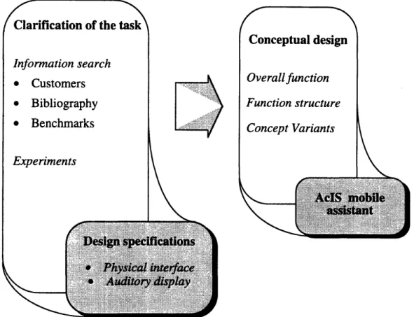
The present work includes the two initial phases in the development cycle of the auditory-cued interactive space (AcIS). They are: the development of the design specifications and the conceptual design. Figure 1 shows a schematic of the process.
..S sL~
Vesign specuicaions
*
I
Physical interface.k I jd
Adory
display
FIGURE 1. SCHEMATIC OF THE DESIGN PROCESS AND ITS OUTCOMES
The outcome of an information search and a series of experiments served as the guidelines for the design of the physical interface and the auditory display of the AclS, respectively. The requirements of a sample of customers, the ideas and opinions from bibliography in visual impairment and child development, and the benchmark of products and solutions to problems of similar nature provided some general requirements primarily addressing the physical interface. A series of experiments with blindfold sighted and visually impaired subjects clarified further the task and provided the necessary information to complete the design specifications. A systematic approach during the conceptual design phase includes the definition of a function structure, the synthesis and evaluation of three concept variants and the detailed description of a promising concept. The work also presents some recommendations to continue the development of the AclS.
' l iilr ii-•Jli i ll l i i l IVI
II IIC~LLIUI.JI U LIIt LIL•
Information search
* Customers * Bibliography * Benchmarks
2 Information Search
In order to clarify the tasks and constraints in the design of the auditory-cued, interactive space (AclS), a group of customers and the solutions of similar problems served as the two primary sources of information. Both were complemented by a bibliographical search.
2.1 Understanding customer requirements
Teachers, aides and students of the Lower School at Perkins School for the Blind represented the primary customers. Among them, the students were the target users. ASTM and the US Consumer Product Safety Commission safety standards were also considered. Parents and lawyers at Perkins and the MIT COUHES Committee were later involved in this project during the experimentation phase.
Children of the Lower School at Perkins
The population of students at Lower School were legally blind children between 6 and 15 years old with different levels of mental disorders and learning disabilities. Some of them had some minor hearing disability, but this was not consider a relevant constraint within this population.
During the usual playground sessions at the Perkins' playground, a group of children showed different levels of environment awareness, willingness to interact and play behavior. Their interaction was primarily with their aides, with themselves and with the immediate environment. Most of them did not move by themselves beyond their positions unless guided by their aides. The way they enjoyed the playground session was through their favorite sensory stimulation: one child enjoyed staying inside the slide making echoes for the whole session, another liked lying on the grass while playing with sticks and the grass, some others preferred swinging and rocking, or just listening to stories from the aide.
During a volleyball session of another group at the Gym, the play behavior was similar. They reacted once the big, colorful ball was close enough, helped by the encouragement of the teacher who coordinated the game. The interaction among them
and the movement from their initially fixed positions were almost none. The level of excitation during the game was varied from player to player.
In general, to characterize their abilities and behavior by simply looking was a very difficult task. However, some commonalties could be perceived: their initiative to be at their favorite place or activity; their need of stimulation through some of the remaining sensory channels, i.e. hearing, cutaneous, kinesthetic or vestibular; and their need of guidance to move beyond a current position.
Specifications from the aides, teachers and experts of related fields
Aides and teachers answered a questionnaire and commented about the needs, likes and musts for the design of a generic play space for students of the Lower School. They also provided a list of requirements compiled for the design of their current playground. A bibliographical search was also developed to gather the characteristics of the ideal developmental play space from other experts in the fields of child development
and visual impairment and blindness. The following list summarizes the core requirements:
* Accommodate all skill levels * Be safe and predictable
* Encourage initiative and independence * Stimulate interaction
* Be fun and rewarding * Be always supervised * Be inexpensive
The versatility to accept all skill levels was a major requirement to guarantee the usability of the play environment by this population. This implied accommodating their physical, sensorial and cognitive differences as well as their different educational levels.
Another major requirement was to ensure the safety of the children. For this, the play environment had to be safe, reliable and easily supervised. Not only the safety of the children but the fear of liabilities were very powerful considerations in evaluating any alternative concept.
The environment had to be recreational and developmental, that is, it had to encourage initiative and independence, stimulate interaction and be fun and rewarding, as the goal of this project established.
To be inexpensive was the other desired requirement of this environment. To present a very expensive solution could be the tendency considering the current possibilities of technology. However, educational organizations for the visually impaired children could not afford such alternatives.
Standards
Safety standards were collected from ASTM and the US Consumer Product Safety Commission. These are concerned with the safety features needed around the use electrical components in consumer products. None of the them were relevant at this early stage.
2.2
Prior art
Both electronic travel aids and auditory environments for art and entertaining are of similar nature to the AclS.
Different kinds of electronic travel aids have been developed since 1960 to convey information about the immediate novel environment through hearing and/or haptic interfaces to the blind. These devices allow users: to avoid bumping into obstacles such as other travelers, lamp posts or street signs, to keep a straight path, etc. A summary of some of them follows:
* The SonicGuide [3] is an ultrasonic transmitter-receiver device mounted in a pair of spectacles that have special nonoccluding ear molds for receiving signals reflected from objects in the environment. It is connected to a power supply that can be carried in the pocket. Its binaural display uses pulsing sounds varying in pitch, intensity, quality and repetition speed to convey the information. Through training, the user learns to differentiate the sound of a brick wall from the sound of a tree or metal garbage can, yet still hear the other sounds and noises around him. It is effective for detecting overhanging objects and obstacles up to 15-20 feet away and it is used with a cane or a dog.
* The laser cane [3] is a specially designed long cane which emits pencil-thin beams of colorless light to detect head-height objects 20 feet ahead and changes in the terrain such as drop-offs, curbs, and manholes. It alerts the user by means of vibrating pins or a pin and audible signals. Through it, the user can find a safe travel path, but it does not provide the wealth of detail about the texture and structure of the environment that the SonicGuide sensor does.
* The Pathsounder [4] is a clear-path indicator. It is an ultrasonic device in a small box worn on a neck strap that display an audible buzzing sounds when there is a waist-height object 6 ft ahead and a distinctively different high-pitched beeping sound when an object is within 3 ft of the user. It is not intended for dog guide users.
The Blind Man's compass [5] displays an acoustic image so that the direction of the perceived sound source is also that of magnetic north a solid state magnetometer has already measured.
The Auditory Directional System [6] provides a "musical pathway" for blind persons to follow to get to interior destinations in an institutional setting. The system's components are a compact disc player and a network of speakers, infrared "people"-detection equipment, and a computer-controlled speaker-sequencing system. To engage the Auditory Directional System, the blind resident pushes a centrally located button for a particular destination. When the person arrives at the first musical cue, infrared sensors detect the person and activate the next speaker. The presence continues to activate each subsequent speaker until he or she reaches the final destination. To trigger the detection process, the resident's clothing is equipped with a retro-reflective tape.
A new type of travel aid project called MoBIC, Mobility of Blind and Elderly People Interacting with Computers [7], has the primary goal of helping blind and elderly people in fixing their position and finding their way in towns. For this purpose electronic positioning systems (GPS) are used in connection with digital maps, geographic information systems (GIS). The MoBIC Travel Aid (MoTA) assists the user in planning journeys using the digital maps and the MoBic Outdoor System (MoODS) helps to execute these plans by matching the information in its GIS, against the position provided by the GPS during journeys. Thus, it assists the traveler in reaching his goal. The MoODS is a secondary aid, complementing primary aids such as the long cane or guide dogs.
Some human-activated auditory environments has been created for the recreation of sighted people. Christopher Janney, a fellow of the MIT CAVS, and MIT Media Lab
groups are some of the constant innovators of these environments. The description of a human-activated recreational environment follows.
Music in Motion was an experiment in using the body as a musical interface created by students of Tod Manchover's "Projects in Music and Media" course at the MIT Media Lab in 1994. Each person who participated in the six-minute-long program (one person at a time) became a real-time wireless transmitter with the help of sensors from the Media Lab Physics and Media group. Motion within the room informed the sensor devices, which in turn communicated to a complex computer sequence. The body's position in the room was the only element which determined the final musical result. Each visit into the room was a unique experience due to the large number of variables involved. Five separate pieces had been written in different but complementary styles: acid jazz, industrial, ambient, pop, and Indian classical. Each piece was assigned to its own zone: one in each of the corners and one in the center. Walking around the perimeter and center of the room triggered different versions of the pieces and mixed them in unique ways. The lighting for this installation maintained the space as an auditory rather than a visual space by using minimal focused lighting. It incorporated live video feed which fragmented the image of the body and projected it in monochromatic patches on the floor.
2.3 User-environment interface
As past experiences in developing auditory interfaces for the blind have demonstrated, not only the technology integrating the system but also the usability of the system is very important for the success of this environment. Thus, both physical and auditory interfaces should be carefully designed considering the physical, sensory and cognitive skills of the target users. The following chapter addresses this concern through experimentation and analysis.
3 The Experimental Auditory Environment
"Pure logical thinking cannot yield us any knowledge of the empirical world; all knowledge starts from experience and ends in it. Propositions arrived at by purely logical means are completely empty as regards reality."
Albert Einstein
3.1 Overview
The experimental auditory environment (EAE) is a research setting created to explore the feasibility and build the auditory display specifications of the AcIS. The nature of these experiments was not descriptive but experimental. The fundamental purpose of the experiments was to clarify the path in the synthesis of the AcIS. Three main questions were addressed through the experiments:
* How feasible is the auditory representation of the space?, * what are effective auditory displays?, and
* what effects does such an environment have on the children?
The two sets of experiments performed addressed the navigation of a single user. A first set of fifteen experimental sessions with thirteen blindfolded MIT students produced initial guidelines about the auditory representation of the space and the abilities of the subjects in performing some spatial tasks. A second set of five experimental sessions with three visually impaired children provided the final guidelines for the synthesis of an auditory display. This auditory display would enable the mobility of a single visually impaired child. All the experiments were videotaped to help in posterior analysis.
Even though the experiments revealed results for the navigation of a single user, these results and a bibliographical review allowed to infer an auditory display for a multi-user environment.
A description of the experimentation setting, subject samples, experiments and their results follow.
3.2 Experimentation setting
The experimental auditory environment (EAE) is illustrated in Figure 2. The function of the EAE was to display auditory information to a single subject through wireless headphones as she moved about a defined area.
eedback trackers
FIGURE 2. EXPERIMENTAL AUDITORY ENVIRONMENT
The main components of the EAE included a grid area, an audio system and two "human trackers". During a 2-D experiment, two "human trackers" identified and tracked the subject's position relative to a Cartesian coordinate system laid out on the floor. Every tracker looked at one dimension. Once a tracker had identified the respective subject's coordinate, he mapped the coordinate to the corresponding auditory coding level (ACL) by either pushing a button on a hand-held keypad or saying the ACL, e.g. "five" through a microphone. The signal from the keypad went to either a built-in tone generator that produced pure sounds or a sound module that generated pulse speeds. Then, these auditory signals (tones, pulse speeds and/or voices) went to a mixer that channeled all the signals to both a speaker set and a transmitter-receiver headphone set. Thus, depending primarily on the accuracy and celerity of the trackers' response, the subject received feedback about her position over the grid area.
The following sections present detail descriptions of the hardware, the alternative auditory displays and the trackers' mapping strategies. Advantages and disadvantages found in this experimental setting are outlined in section 3.5.4
3.2.1 Hardware description
A description of every EAE component follows: A variable-resolution, paper grid
A Cartesian coordinate system was made of paper strips. The first set of strips was taped down to the floor in parallel, with another set going orthogonal over the first set. The pattern resembled a checkerboard. The straight paths between any two contiguous, parallel strips were called lanes. Every lane was crossed by all the orthogonal strips. The grids implemented at M.I.T. provided a total area for mobility of 900 ft2 using 30-ft-long strips in both orthogonal sets of strips. Resolutions of 15, 10 and 5 lanes per side were used. These resolutions corresponded to lanes of 2-ft, 3-ft and 6-ft wide, respectively. In the Perkins School setting, the total squared area for mobility was 256 ft2 , using 16-ft-long strips and making 8 lanes of 2-ft wide. At both settings, the grid was laid out on gym floors.
* Two trackers
Placed at two orthogonal boundaries of the grid, two people named "trackers" worked matching the subject position to the respective X and Y position coordinates specified on the grid. What they identified as coordinates depended upon the mapping strategy used throughout the experiment. Once the coordinates were recognized, they were also responsible for the production of the corresponding auditory information, triggering sounds by pressing buttons on a hand-held input device or speaking the coding through a microphone. The demanding multi-tasking of these two human beings in the system was a major factor affecting the effectiveness of the auditory display. This issue is discussed in section 3.5.5
The touch-sound board used by one of the subjects consisted of a 14.5-in-square piece of cardboard covered with a smooth, green surface, a rectangular array of 8 by 8 white tapes of lin by 1.25in at its top, and a yellow 1.5-in-square piece of cardboard at one corner. The tapes' surface had to be coarser than the background's surface in order to be effective. The touch-sound board worked as an auditory-haptic simulation of what was happening on the grid. It was intended to ease the subject's visualization of her movement on the grid as she slid her finger on the tape-button array and triggered the auditory display. The two trackers worked with the touch-sound board in stead of the grid. The tapes were separated 0.5[in] in the direction of their longer side and 0.75[in] in the direction of their shorter side. In this way, a subject could feel the change of direction not only from her kinesthetic senses but also from her cutaneous sense to reinforce the changes heard through the auditory display. The yellow piece worked as a visual reference in case the subject had some vision left.
Two Magical Musical Sticks (Radio Shack Catalog No. 60-2514)
This battery-powered toy was used by the trackers as a hand-held input device and sound generator. It consisted of a numbered-25 button keypad with a keyboard-like layout, a built-in tone generator circuit and a built-in speaker. Its 25-tone sequence represented a western chromatic scale. The button layout facilitated the coordinate entry to trackers due to its compatibility with the array of strips in the grid. Trackers could also receive auditory feedback from their operation through the small built-in speaker. When working as a pulse speed generator, the keypad was directly connected to the coding control box. As a sound generator was connected directly to one of the channels of the mixer. The unit price was $5.00.
* Two microphones
Two Radio Shack@, 200[W] Dynamic mikes were used by trackers to speak numbers and letters as ACLs during the respective experiments. The mikes were also useful to give instructions to the subject while she was using the headphones set during the experiment session. They were connected to the channel ports of the mixer.
* A six-channel stereo mixer
A Boss BX-40, 4W mixer was used to control the display of every sound source input to the mixer.
* Personal training Lab (Cleveland Institute of Electronics)
The only purpose of this device was to serve as a AC/DC power converter to supply the +/- 6V needed in the sound module circuit.
* Sound coding module
This Percussion Synthesizer, in Radio Shack Cat. No. 276-5011A, consisted of a set of knobs with an electronic circuit that was able to generate sounds at different pitches and pulse speeds.
* A 900-MHz wireless headphone set
This set comprises both the 900-MHz wireless headphones and the audio transmitter. The display through wireless headphones eased the subject's attention on the auditory information. This helped the subject concentrate on the processing of the auditory information as she moved. Cables would also have caused blurring of the paper grid and entanglement of the subject.
* One loudspeaker
A Sony@ SRS-58 loudspeaker with built-in amplifier was used as auditory feedback display for both the tracer and the video recording. It was also used as the auditory display for the subject when not using the headphone set.
* A stop watch
A stop watch was used to measure performance and reaction time of subjects in the experiment described in 3.4.4
* video camera and loudspeaker for recording
Sanders et al.[8] reports that "in field studies often there is no opportunity to replicate experiments a sufficient number of times, many variables cannot be held constant, and often certain data cannot be collected because the process
would be too disruptive." In this regard, the audio-visual tape recordings helped to verify and complement the work in the field.
3.2.2 Auditory display
Auditory codes
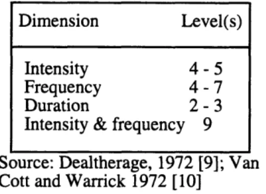
Both electronic sounds and speech were used to code the spatial information. The following combinations of auditory codings were used to map the x-y Cartesian coordinates on the grid area: pitch vs. pulse speeds, pitch vs. numbers, alphanumeric, and numbers vs. numbers with either male-male or female-male voice combinations. Neither sound intensity nor duration were considered due to their low level of identification as
d rcsriheed in tahle 1
Source: Dealtherage, 1972 [9]; Van Cott and Warrick 1972 [10]
TABLE 1. LEVELS OF AUDITORY DIMENSIONS IDENTIFIABLE ON AN ABSOLUTE BASIS
Sound intensity and duration depended on the subject comfortability and "trackers" respectively.
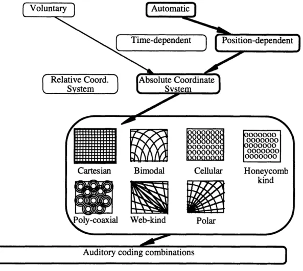
Display modes
The display mode defined when the auditory information was displayed. Figure 3 shows the auditory display structure assumed during this work. The two primary display modes are voluntary, e.g. the subject pushing a button, and involuntary or automatic, i.e. the system decides when to display. These experiments are concerned with the automatic mode. Automatic display can be governed by either a time function or a position function. Due to the EAE system structure, the display of the auditory code was
position-dependent, i.e. the auditory code was displayed whenever the "trackers" mapped the position of the subject to a cell or a line on the grid. Time-dependent display was not explored. However, the use of a time-dependent display may not have been useful for this work. One of the motivations for the visually impaired children to move should
Dimension Level(s)
Intensity 4 - 5
Frequency 4- 7
Duration 2 - 3
Intensity & frequency 9
dt-Qri
come from the curiosity for the unexpected sounds in the space to be explored. A sense of control over the production of the sounds is also an important educational characteristic. Relative Coord. System Cartesian Bimodal Web-kind Cellular Polar Honeycomb kind
FIGURE 3. AUDITORY DISPLAY STRUCTURE
3.2.3 Spatial mapping
Two strategies were used by the "trackers" in mapping the coordinates of a subject to the auditory code levels:
Line-mapping
An auditory code level was displayed once when the subject was crossing a new strip. Therefore, when walking along one strip, the strips being crossed were the only
21
IMMENNOMMMOMMM
,
ýýZJ
ones being mapped to auditory code levels. Parallel strips, representing constant lines in the x or y coordinates of the Cartesian system, were identified with one auditory code such as numbers, letters, pulse speeds or pure sound pitches.
Cell-mapping
Two auditory code levels were displayed once, one after the other in most of the cases, when the subject walked over a new cell. The two auditory code levels represented the two respective orthogonal lanes crossing over the cell mapped. Using this strategy, parallel lanes and not the parallel strips were identified with one auditory code.
3.3 Subject samples
Sighted MIT students and visually impaired children were the two main groups of participants in the experiments. Even though the issue in choosing subjects for experimental research is to select subjects representative of those people to whom the results will be generalized, the availability of sighted MIT students made possible to gain an initial understanding of the environment. This understanding set some references about the use of the auditory display and simplified the work to be done with the visually impaired participants. None of the subject samples were initially familiar with the experimental environment and its tasks. A description of the two samples follows:
Blindfold sighted subjects
Thirteen blindfold sighted MIT students, 20 to 27 years old, were participants during the first set of experiments. The participants were either undergraduate or graduate students in either engineering, science or humanities at M.I.T. Two participants were graduated pianists and had perfect pitch skills, seven participants were active music listeners and the other three participants were less frequent music listeners. None of them had visual, hearing or learning disabilities. None of them were tone-deaf.
Visually impaired subjects
Three legally blind children participated in the second set of experiments. The participants were students in the summer program at Perkins School for the Blind. Further relevant information about every participant follows:
* Child I, a 9-year-old boy, is totally blind and learning disabled. He also has some behavioral problems. During a year and a half at Perkins School he participated in chorus and music classes. He has neither tone deafness nor perfect pitch skills.
* Child II, a 11-year-old boy, is legally blind and learning disabled. He was at Perkins School only for the summer program. He also attended chorus and music classes. He has neither perfect pitch skills nor tone deafness.
* Child III, a 15-year-old girl, is totally blind and learning disabled. She has minimal to moderate brain damage. Even though she is cognitively involved with her surroundings, she has problems following directions. However, her disabilities are still less critical than the ones in most of the students of Lower School.
3.4
Experiments with blindfolded subjects
A first set of four experiments was performed by blindfold sighted MIT students using the EAE setting described in 3.2. The primary purpose of these experiments was to learn about the capacity of sighted subjects to perform spatial tasks with no visual information in an area represented through auditory codes. The experiments also revealed some guidelines to convey the spatial information through auditory displays.
The spatial tasks in this set of experiments included: to find positions in 1-D (in a 2-D space), to find positions in 2-D and to follow geometrical paths. The total area for mobility was obstacle-free. The only guidance provided to the subject was the auditory coding mapping her or his position. No subject's azimuth coding was displayed. Wireless headphones displayed all the information to the subjects. Detailed explanations of the tasks and auditory displays of these experiments are provided from section 3.4.1 to section 3.4.4.
A qualitative analysis was developed from observations, video records and subjects' feedback. The observed subjects' accuracy in finding given target positions or following geometrical paths was used as the measure of the effectiveness of the particular
auditory display. Performance time was not included in the criteria to neglect the differences in the subjects' motor abilities.
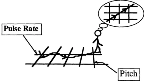
3.4.1 Mobility in 2-D with a 1-D task
The grid and the auditory display settings used in this experiment are illustrated in Figure 4. They consisted of:
* a 30-ft by 8-ft striped, rectangular grid, with 16 x-lines and 4 y-lines creating spatial 2-ft square cells;
* a sequence of 16 pure pitches in the western natural scale and a sequence of 4 discriminable pulse speeds to represent lines in both x and y coordinates, respectively;
* line mapping as the position-dependent display mode, i.e. every line represented an auditory code level; and
* wireless headphones to display the auditory information to the subjects.
Discrete pulse rate levels
4 Hz
I I II1 I . I I I I I I I I I arget ne Iking lane1111l1
81 HI T I I (\
1 I Discrete pitch levelsI I-8 Hz
440 Hz 800 Hz
FIGURE 4. EAE SETTING USED FOR THE 1-D EXPERIMENT TASK
Five blindfold sighted MIT students participated in two sessions of this experiment. The task was to find a target position along one direction. One pitch level mapping the target line represented the target position. The system mapped the 2-D positions of the subjects using the line-mapping display mode. The pulse speed levels representing the lines parallel to the walking lane gave the subjects an idea of their off-set
from the correct path. In most of the trials, the subjects were initially placed facing the target position. Only in a few cases, they performed the task initially facing the wrong azimuth. They listened to the pitch level corresponding to the target line. Then, they were asked to walk and stop at the target position. The task was repeated at least three times by all the subjects.
3.4.2 Mobility in 2-D with a 2-D task
Five blindfold sighted MIT students participated in this experiment. The task of the subjects was to find and stop at the position where they would listen again to the pair of auditory code levels displayed to them before starting to walk. This pair of auditory code levels represented the x-y coordinates of the target position. Either wireless headphones or open loudspeakers displayed the auditory information to the subjects. The experiment used different grid and auditory display settings to learn about their effects on the performance of the subjects. A full 30-ft-square Cartesian grid with parallel lines every 2, 3 and 6 feet, as described in section 3.2.1., was used as the navigation area. "Trackers" used line-mapping as the position-dependent display mode, i.e. every line represented an auditory code level. The auditory coding combinations used to represent the Cartesian coordinates were: pitch vs. pulse speeds, pitch vs. numbers, alphanumeric and numbers vs. numbers with either male-male or female-male voice combinations.
Three subjects tried an azimuth cue in one opportunity. Four well-discriminable pulse speeds mapped four discrete azimuths. The coding was tried alone by asking subjects to point in the direction cued by a pulse speed displayed while standing still. Then, subjects participated in the 2-D experiment with both the pulse-speed azimuth cue and the number-pitch position coding.
3.4.3 Mobility following geometrical figures
Only one blindfold sighted MIT student participated in this experiment. His tasks were to follow square, triangle and circle paths in the experimental setting described in the previous section. For this particular experiment, parallel lines every 3 and 6 feet were set for the grid and pitch vs. pulse speeds, alphanumeric and male/male-voiced numbers were used for both resolutions. When using the numbered coordinates, the (0,0) of the
system was moved toward the center of the grid and the subject was asked to start following the path from that position. "Trackers" used line-mapping as the position-dependent display mode. Wireless headphones displayed the auditory information to the subject. Observations of the subject's performance under these different settings were drawn from video records.
3.4.4 Mobility on the triangle
3.4.4.1 Experiment objective and design
The objective of this experiment was to prove that the auditory-cued environment is a potential educational tool, i.e. blindfold sighted subjects are able to learn and improve their mobility in this space. Auditory memory, space visualization, sound discrimination and haptic-auditory channels' interrelation were some of the perceptuo-cognitive abilities involved in this learning experience.
2
Tones
///0T! I
~/"
ji /1/ /
Numbers
FIGURE 5. SUBJECT FOLLOWING THE TRIANGULAR PATH
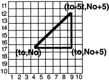
Four blindfold sighted MIT students participated in this experiment. The task of every subject was to walk over the perimeter of an isosceles triangle in the least time possible as Figure 5 shows. Figure 6 illustrates the setting. The triangle was set over the Cartesian grid described in 3.4.2. with parallel lines every 2 ft. Pure-sound pitches in a pleasant range and numbers, 1-10, mapped both Cartesian coordinates, respectively. The position-dependent display mode used in this experiment was cell-mapping, i.e. the subject listened to one pitch and one number in every new cell they walked into.
/·~-~--~--~c~---~---·1
I
i
The goal of the subject was to optimize a performance time index (PTI) that measured the skills described above. Every subject had four opportunities to do the task and produce the best performance time index possible.
The experiment analysis was based on: the sequence of PTIs, accuracy in getting every vertex and the qualitative descriptions of the performance of every subject. The PTI was equal to the sum of the performance time and the time penalties due to the number of reminders and inaccuracies during the respective trial. The reminder time penalty was equal to 15 seconds times the number of times the subject asked for the auditory code of the next respective vertex. The inaccuracy time penalty was equal to 15 seconds times the number of cells off from the correct vertex cell.
tl
t2
t3
t4
t5
t6
t7
t8
t9
tl
No+5)
So+5)
FIGURE 6. TRIANGLE EXPERIMENT SET-UP
3.4.4.2 Experimental task description
The task of every subject was to walk over the perimeter of an isosceles triangle in the least time possible. Before setting the triangle path, the subject was blindfolded spinned and guided to walk in loops confused. To start performing, the subject was located in one of the 45' corners of the triangle facing the 90" corner. "Trackers" displayed the three pitch-number pairs corresponding to each of the vertices of the triangle in the same order the subject needed to find them. The last of three pitch-number pairs corresponded to her current position, i.e. where the subject had to return to complete the triangle perimeter. Once the last pair of codes was given, the subject started walking
and the stop watch started running to time her performance. The subject clapped with her hands once she thought she was on the desired vertex, and continued to complete the triangle perimeter. At any time of her performance, the subject was able to ask for the next vertex to find by raising one hand. However, 15 seconds were added to the respective PTI to penalize every reminder during her performance.
The subject had four opportunities to do the task and produce the best PTI possible.
3.5 Observations from experiments with blindfolded subjects
The results and analyses of the set of experiments performed with blindfold sighted MIT students follow.
3.5.1 Auditory representation of the space
The relevant information
Coding of position was necessary but not sufficient to allow the natural mobility of subjects within the space. The experiments suggested that an azimuth cue is also needed. A subject was able to know when she was walking along one of the coordinates by listening to the position coding displayed. However, her use of the auditory information in directions other than along one Cartesian coordinate was ineffective. Fine changes in orientation within the limits of a lane may have not been perceived either. Moreover, subjects were not able to return effectively after accidentally leaving the grid area during the 2-D experiments. They seemed not to be well aware of their orientation before leaving the grid. Possible azimuth cues may be: the order in which the two coordinate codes are displayed; relative intensity, duration and/or a time function between the two coordinate codes; the headphones interaural intensity; and/or another
sound. See the section titled "Relation between a subject's mobility and the display" in 3.5.3 for further analysis.
Boundaries of the grid
A cue to inform participants that the boundaries of the environment are reached may be very useful for the actual application.
3.5.2
Auditory coding and display
Auditory codes and their discriminability
Among the coding combinations used, the alphanumeric was the most effective to provide position information. Pulse speed vs. pitch represented the worst combination. Other combinations such as male-female numbers, male-male numbers, number-pitch were also effective, in decreasing order, in displaying position information.
The subjects were not able to discriminate effectively the pulse speed-pitch coding during the 2-D experiment. They could recognize that they were walking in the correct or opposite direction when walking along one of the coordinates, i.e. they knew that either the target pulse speed or the target pitch was higher or lower than the one they were listening to at their current positions. Pulse-speed coding was particularly ineffective and even more so in regions of high pulse speeds where discriminating between two pulse speeds was even harder. This created confusion such as the one illustrated in Figure 7, where subjects were thinking of diagonal-to-the-grid walking, i.e. crossing new pulse speeds and pitches, while actually moving off and on the pulse speed coordinate. Pulse speed coding was uncomfortable to the subject to the point of reducing the effectiveness of the other coordinate coding. Along the coordinate coded by pitch, blindfold sighted subjects were always more accurate.
FIGURE 7. CONFUSION DUE TO LACK OF DISCRIMINABILITY
One EAE setting coded both coordinates with numbers using both male-male and female-male voice combinations. Male-male voice combination confused subjects,
making them shift the two coordinates. The female-male voice combination was successful.
Alphanumeric was the most easily understood coding used. The least effective subject could find the targets directly using this coding. Figure 8 shows one of the his performances. With speech coding in general, the navigation behavior was more confident, as may be expected. Still, subjects used the orthogonal mobility strategy to be described in 3.5.3.
lbject's path
get position
ABC DE FGHI J K
FIGURE 8. TRIAL WHILE CODING WITH ALPHANUMERICS
The amount of information
The amount of auditory information subjects used effectively was relatively small. This result may have been caused by the single and irregular display mode of the EAE. When trackers displayed both codings at the same time during the 2-D experiment, the subjects clearly reflected their limitation to understand the information by slowing down or stopping their movement. This suggests that subjects were trying to separate the information in their minds and make it understandable in their context. Another behavior the subjects followed was the single-coordinate optimization explained in 3.5.3.
initial initial
discrete
speeds
Numbers
FIGURE 9. 2-D EXPERIMENT CODING FOUR DISCRETE AZIMUTHS
Either locating each coding display in different apparent positions around the subject through 3-D technology or creating a single multidimensional code, may reduce the coding demands. Coding one coordinate with numbers and the other with the pitch of the voice is an example of the latter alternative.
During one session, an additional tracker mapped four discrete azimuths to four well discriminated pulse speeds as Figure 9 illustrates. Subjects did point in the right directions when they listened to the pulse-speed cues alone. During the 2-D task, the setting added this cue to the number-pitch position coding. The information overcame the subjects. Three subjects with ten and more years of musical background, two of them with perfect pitch, could not manage effectively the information during the 2-D task. The subjects' reaction was to avoid the azimuth cue by walking facing always the same direction. The tracker's delay in triggering the pulse speeds and his difficulty in mapping the respective angles also made the cue ineffective.
Mapping and information feedback
Using the EAE, the updating of information depended on two factors: the grid resolution and the mapping strategy used by the trackers. The experiments suggested that a "continuous" and complete information display would allow subjects to feel more confident and move more naturally in the space. The EAE settings to achieve such a display are: relatively high grid resolution (2-ft-square) and cell-mapping, respectively.
The need of an azimuth cue was reaffirmed but difficult to implement as explained above.
The grid of the EAE can be thought of using its analogy to a A/D converter. The path of a subject was the analog signal and the lines or cells sampled along the path, depending on the mapping strategy, were the digital signal. The higher the resolution of the grid, the better the path was approximated and the finer the movements that were possible. Figure 10 illustrates the point. Trackers' abilities limited the position-dependent display frequency of the EAE. The higher the grid resolution and the velocity of movement of the subject, the more irregular and ineffective the tracking of the system was. The experiments suggested that a 2-ft-square resolution was enough to achieve a good approximation of the movement of the subjects. This resolution would also be safe to allow for the multi-participant interaction in the space. However, a higher resolution, or sampling frequency, could be even better. Its effects would need to be studied through a more reliable system.
FIGURE 10. AN EFFECT OF THE DISPLAY ON SUBJECT'S VISUALIZATION
With mapping lines every 2 feet, subjects could not distinguish the different degrees of their diagonal orientations from the changes in the codes displayed. Disregarding the lack of an azimuth cue, this was due to the chaotic and separate presentation of the two codes in the line-mapping display mode and the little appreciable difference between the diagonal and the longitudinal distances from line to line. In addition, trackers' inaccuracy and delays also affected the performance. Lower
resolutions, lines every 3 or 6 feet, were set with the expectation of more noticeable differences between two diagonal orientations. Contrarily, subjects' perception got worse. Moreover, the subjects' mobility became unnatural and courser while they tried to obtain feedback from their orientation through the pair-comparison strategy explained in 3.5.3.
Subjects needed not only a "continuous" but also a complete information display. The experiments suggested that subjects had a more natural mobility when listening to both coordinate codings. Doing the 1-D task with the line-mapping criteria, a subject's
tendency was to verify her orientation along her walk by moving herself off to one side to trigger the other coordinate code as Figure 11 shows. Certainly, an azimuth cue was needed. The solution implemented during the triangle experiment was the cell-mapping display mode that displayed both Cartesian coordinates in every cell reached. Thus, the unchanged coordinate was reaffirmed avoiding an unnecessary demand on memory. Subjects showed a more confident and natural movement with the cell-mapping mode than with the line-mapping mode, in a 2-ft-square-cell grid.
initial position
target position
-FIGURE 11. A SUBJECT CHECKING TO FEEL SURE ABOUT HER ORIENTATION
The display means
Three subjects, two of them with perfect pitch, participated in the 2-D experiment using both headphones and open sound sources, i.e. a loudspeaker and one tracker's voice. The use of headphones was better for letting the subjects concentrate on the auditory codings and isolate them from the sounds of the natural site. The use of open
sound sources provided an orientation cue and a better perception of both codings, and eliminated the subject's sensation of isolation.
The two open sound sources used, one tracker's voice to display numbers and one keypad loudspeaker to display pitches, were either static at the boundaries or moving along the boundaries following the corresponding subject's coordinates.
One of the subjects with perfect pitch said that "it was easier to navigate without headphones because [she] could discriminate between the two sound sources [due to their physical separation] and orient [herself] in a better way." In fact, the other subjects also presented a more natural mobility in the space. They also seemed to orient themselves in a better way with the open display setting. One proof of their better orientation was their ability to return to the grid easily after walking beyond its boundaries.
Contrary to the subject's freedom and comfort offered by the open display, the use of headphones and the isolation produced by their use seemed to degrade subjects' performance and attitude. One drawback was the greater effort subjects had to make to listen to the coding while moving, especially to listen to the tracker's voice.
The use of moving sound sources drew no particular conclusion about its effect on subjects' mobility. The subject without perfect pitch expressed to be confused with the moving display mode while one of the subjects with perfect pitch said "it was easier to listen to". Different voice and loudspeaker intensities may have caused such a contradiction.
3.5.3
Subjects' skills and mobility behavior
Previous hearing training
When coding with sounds, subjects with educated hearing, i.e. frequent music listeners or musicians, performed better than those who had little exposure to music. Subjects with perfect pitch performed perfectly using either pitch or alphanumerics.
Subjects largely educated in Eastern countries had problems following the pitch coding. This could be associated to their larger familiarity to eastern tonal systems than to the western tonal system used in the experiments.
Auditory memory
The auditory memory of the subjects was an important influence on the effectiveness of the auditory codes. To remember the two coding levels of the target
position was one of the difficulties always present in the 2-D experiment. The experiments suggested three main factors challenging the code retention of subjects: the way subjects moved on the grid, their musical training, and the irregularities of the display explained in 3.5.4.
The way they moved on the grid, i.e. how many and the order of the code levels they heard, the time spent, and how fast they moved along a coordinate before getting into the target position, affected their retention of the coding of the target position; and thus, their possibility of finding it.
Their musical training affected their memory particularly when using pitch coding. People with musical training moved more effectively in the space than those without it. The type of tone interval between the respective current location and the target location also seemed to affect their ability to retain the codes. A pursuit-tracking display, i.e. in which target and successive current locations are displayed together, may be a solution to the memory problem.
Single-code optimization
Single-coordinate or single-code optimization was a common strategy subjects followed. During the 2-D experiment with the line-mapping display, subjects tended to walk keeping one coordinate constant to listen to only one auditory code and solve it before walking in the other orthogonal direction. In this way, they avoided the confusion of listening to and optimizing both auditory codes at the same time. Figure 12 shows a subject walking along a Y lane after listening to the auditory code level that mapped the correct Y coordinate. The subject got lucky this time by turning 90" in the right X-direction.
target position
/
K,
I I
Y coordinate
X coordinate
initial position
FIGURE 12. SINGLE-COORDINATE OPTIMIZATION
With the line-mapping mode, pair-wise comparison of two contiguous auditory code levels was the strategy that subjects followed in the 2-D experiment to verify their orientation along one coordinate. Subjects were not able to know if their orientation along one coordinate was correct until listening to the second level of the respective auditory code. This meant crossing over two subsequent lines. Figure 13 illustrates the extreme case were the low resolution of the grid made the subject deviate at least 7 ft before verifying the orientation. These frequent checking made him forget the original target code levels and finish in another position.
low
Pulse
p:
Rates
pzhigh
t position
1 position
tl t2 t3 t4 t5 t6low
Pitch
high
FIGURE 13. PAIR-COMPARISON WITH A 6-FT-SQUARE-CELL GRID
With the cell-mapping mode, subjects needed to step over the next cell to check their orientation.
Relation between a subject's mobility and the display
Mobility behavior followed display design. During the first set of experiments, the auditory display imposed certain common patterns on the mobility of the subjects, as illustrated already in Figures 12 and 13. The experiments suggest that the auditory display, i.e. the coordinate system, its resolution and coding design, defines the pattern of the subject's mobility in the space. It may also be expected that the frequency of a time-dependent display would force an upper limit on the velocity of movement of the subjects. For the environment to be successful, subjects need an intuitive feedback to move and the design of this feedback should not shape their movements.
2
2
=?
FIGURE 14. FOLLOWING A CIRCLE IN THE CARTESIAN GRID
The Cartesian coordinate/line-mapping setting provided a natural frame for movements in its two directions along the coordinates. This display design also reinforced single-coordinate mobility because no orientation cue was displayed. To walk over the perimeter of a rectangle was not difficult if its sides were aligned to the grid. However, a non-aligned square would have been difficult to follow in a line-mapping setting with no azimuth cue. Figure 14 shows a subject trying to process the information displayed to him while trying to walk over an imaginary circular path. During this task, the subject tried to obtain the help from the auditory display at the beginning of his trajectory until he realized that the auditory feedback was forcing him out of the imagined circular perimeter to follow a straight path. At that point, the subject decided that it was better to heed his vestibular and kinesthetic channels to do the task. The criteria the subject used to know when to stop was to walk until the highest pitch he remembered from his path appeared again. The result was an arc of 460". Therefore, the Cartesian coordinate did not present to the subject an intuitive display for such tasks. "It was hard to correlate the coding and the actual figure," the subject said. An absolute polar system would have offered the needed auditory frame for a circular path but not for a square path. Thus, the question was: what kind of position-dependent display is required to
allow pattern-free mobility?
A "streamline" coordinate system (displacement and azimuth) could represent the ideal, intuitive and pattern-free display solution. However, in an interactive space, the auditory coding of an inertial frame would inform absolute positions to the participants reinforcing their localization tasks and their abandonment and reliance on the safety of the space where they move. In this regard, a cell-mapping auditory display with a fine