Design of a Tabletop Lathe Educational Kit By
Marcus Lopez
Submitted to the Department of Mechanical Engineering in Partial Fulfillment of the
Requirements for the Degree of
Bachelor of Science in Mechanical Engineering at the
Massachusetts Institute of Technology January 2008
@2008 Marcus Lopez All rights reserved
The author hereby grants to MIT permission to reproduce and to distribute publicly paper and electronic copies of this thesis document in whole or in part.
Signature of Author... . .... .Me e c ch... e...g..8 partment of Mechanical Engineering
January 18, 2008
Certified by .... "." ".' ...
Cetifed by....
Martin L. CulpepperAssociate Professor of Mechanical Engineering Thesis Supervisor
Accepted by... . ......
John H. Lienhard V Professor of Mechanical Engineering
Undergraduate Officer
MASSACHUSETr-S IisIUT
OF TEOHNOLOGYMAR
0
4
2008
LIBRARIES
AFRCHjEES
Design of a Tabletop Lathe Educational Kit By
Marcus Lopez
Submitted to the Department of Mechanical Engineering on January 18, 2008 in Partial Fulfillment of the Requirements for the Degree of
Bachelor of Science in Mechanical Engineering.
Abstract
The purpose of this research is to create and characterize an educational kit for the mechanical engineering courses, 2.75: Precision Machine Design and 2.72: Elements of Machine Design. This kit is intended to provide instructors with a means to create a positive learning experience by (1) providing an opportunity for students to be innovative, (2) allowing students to better understand the limitations and strengths of their designs, and (3) optimizing the benefit of the learning
experience. Engaging students with a project that motivates and inspires them ultimately produces a more capable engineer.
The redesign and analysis of a table-top lathe is covered in this thesis. The efforts entailed herein revolve around the design of modular lathe that best suits the needs of students and instructors in 2.75 and 2. 72. Additionally, this thesis reviews the fabrication and testing of a prototype used to identify any problems with the manufacturing and assembly.
Thesis Supervisor: Martin L. Culpepper
Acknowledgements
I would like to thank a few people who donated much of their time and resources to help make this thesis project possible. I first would like to thank Professor Martin
Culpepper for mentoring me as I completed this project. Working under his supervision has been a valuable experience.
I would also like to thank Gerald Wentworth at the MIT Laboratory for
Manufacturing and Productivity for his help in fabricating the prototype lathe. I learned a great deal in my many hours spent with him.
Table of Contents
A b stract ... 3 Acknowledgements ... 5 C ontents ... .. 7 F igures ... 9 Chapter 1 Introduction ... 13 1.1 Scope... 14 1.2 Modularity...15 1.3 Student Interest ... 151.4 Overview of First Kit ... 16
Chapter 2 Lathe Modules ... ... 17
2.1 Component Analysis Chassis ... 18
2.2 Component Analysis: Leadscrew ... 27
2.3 Component Analysis: Spindle ... ... 31
2.4 Component Analysis: Carraige ... 35
Chapter 3 Testing... 37 3.1 Test Setup... 38 3.2 R esults ... ... 39 3.3 Error Sources ... 41 Chapter 4 Summary ... 42 4.1 Future Work ... 44
Appendix A Pitch and Roll Analysis Tolerance Information ...45
Table of Figures
Figure 1.1 Figure 2.1 Figure 2.2 Figure 2.3 Figure 2.4 Figure 2.5 Figure 2.6 Figure 2.7 Figure 2.8 Figure 2.9 Figure 2.10 Figure 2.11 Figure 2.12 Figure 2.13 Figure 2.14 Figure 2.15 Figure 2.16 Figure 2.17 Figure 3.1 Figure 3.2 Figure 3.3 Lathe ... 13Illustration of lathe modules ... 17
Exploded chassis ... ... 19
Load path diagram ... 20
Load path diagram ... 20
Tail endplate safety factor ... ... .. 22
Head endplate von Mises stress... ... 23
Head endplate safety factor ... 24
Rail deflection ... ... 25
Head endplate deflection... ... ...26
Leadscrew bearing schematic... 27
Leadscrew bearing detail ... ... 29
Bearing tube assembly... ... ... ... ... ... 30
Bearing tube and chassis interface ... 31
Exploded spindle assembly... ...32
Shaft property table ... 34
Proposed carriage ... ... 35
A ctual carriage ... ... . .... .... ... 37
Carriage measurement points ... ... ... 38
Spindle measurement points ... ... ... 39
Figure 3.4 Spindle runout results ...41 Figure 3.5 Calculated vs. Measured error ...42
Chapter 1
Introduction
The purpose of this thesis is to create and characterize an educational kit for the mechanical engineering courses, 2.75: Precision Machine Design and 2.72:
Elements of Machine Design. This is an important project because educational tools
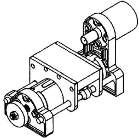
such as this kit provide instructors with the means to create a positive learning experience. The positive learning experience will impact the mechanical engineering world by cultivating innovation and ultimately producing better engineers. Figure 1.1 shows the lathe developed in this thesis.
Figure 1.1: This is a drawing of the lathe developed in this thesis.
The objective of the kit is to provide the materials for a design project. The concept for this thesis is based on a miniature table-top lathe that was originally created for the senior undergraduate machine course, 2.72: Elements of Mechanical
Design, during the spring semester of 2007. This design was initially created by
Professor Martin Culpepper and graduate student Christopher DiBiasio. The project served as an integrated system design project, where students were charged
with the task of transforming a given lathe concept into a detailed design by using the principles that were studied in the course. Essentially, the students in 2.72 were given a set of design requirements, an accuracy specification and several
standardized components. With these resources in hand, the students were asked to apply the design principles that were learned in the course toward producing a completed lathe in one semester. This first offering of the project may be considered to be the first iteration of the kit formally developed in this thesis.
In considering the adaptation of this kit for use in 2.75, the lack of refined design details posed a significant problem. The breadth of engineering problems associated with this holistic approach limits the depth and rigor with which each problem may be addressed and solved. Precision machine design requires that some problems be analyzed on level that borders on being beyond the scope of
2.72. It is therefore necessary to adapt the kit to suit the more advanced educational
goals of 2.75. To this end, three major factors were considered during the lathe development: Scope, modularity, and student interest.
1.1 Scope
First, the engineering necessary for this design must fall within the scope of
the course. Precision machine design encompasses a wide variety of basic
engineering disciplines. If one were to direct the design to some of the basic
components of the lathe, this would distract from the core concepts and thereby lead to student frustration. There is no way to avoid this if the students are to design the entire machine. It is better to scope the project so that the 2.75 students are only
responsible for elements of the machine that focus on precision engineering principles. The thought was that a focus on specific sub-systems would enable students to study, implement and learn that subject matter in more depth and with greater focus on the most critical aspects of precision machine design.
1.2 Modularity
The second consideration was the need to create a modular lathe that possessed individual modules that could be isolated from one another such that instructors could chance the degree of student design effort and freedom without having to redesign the entire lathe. With the modules decoupled from one another, it would become easier to shift the focus of the course and extent of student design freedom from one semester to the next by changing which components the students design. This would give the instructors more flexibility to study how changes to the project could improve student learning, yet the same base components can be used for the unaffected sub-systems of the lathe.
1.3 Student Interest
The final consideration was to create and interesting and engaging project that the students would pursue on mostly their own initiative. It was envisioned that the combination of a tunable learning experience with a motivating project would improve student learning. It was also thought that the modularity and intrest
combination would lead to a situation wherein students could complete a set
number of modules so as to learn precision engineering principles and then focus on a limited number of remaining modules with the aim of making their own
innovations to the project. By cultivating this positive learning experience, this thesis hopes to impact the students in 2.75by: (1) providing an opportunity for students to be innovative, (2) to better understand the limitations and strengths of their designs, and (3) to optimize the benefit of the learning experience.
1.4 Overview of First Kit
Before this discussion moves ahead, it is important to understand the heritage of the design and to identify its flaws and strengths. A thorough review of the lathes from the initial offering in 2.72 was conducted. Several models were disassembled and reassembled in order to obtain an intimate understanding of their characteristics. These machines illustrated how the students' took different
approaches to solving the same engineering problems. A great deal of insight was gained by examining which designs functioned successfully and which designs fell
short of meeting their goals. This knowledge was then used to redesign the project and kit.
This thesis focuses on the design decisions that were made during the redesign of this lathe and the characterization of the design via dimensional metrology. The second chapter outlines the justification of the design choices via engineering, financial, and manufacturability perspectives. Chapter 3 will describe
the experimental methods and related results of performance measurements. Additionally, sources of error are discussed. The final chapter will provide an overview of this project and its contributions. Additionally, the Chapter 4 will include a summary of how the three considerations outlined in this chapter were addressed as well as recommendations for future work on the lathe.
Chapter 2
Lathe Modules
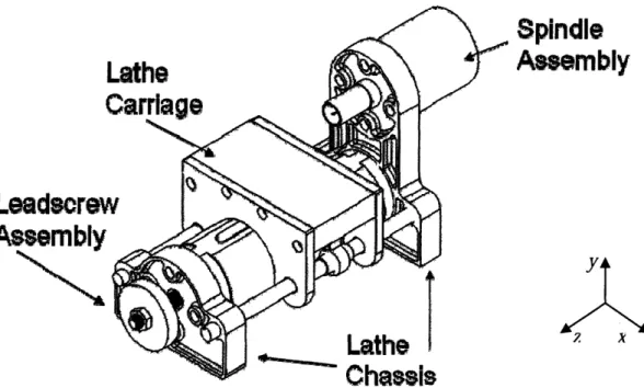
The illustration in Fig 2.1 shows the four basic modules of this design in a fully assembled unit.
Spindle
Assembly
Leadscrei
Figure 2.1: A schematic diagram of a fully assembly lathe illustrating the various
modules of the design.
A
As mentioned previously, the modular approach is a key feature to the success of this lathe as a pedagogical tool. Fortunately, the elegance of the lathe's design makes this task much easier. The spindle assembly, which includes the lathe spindle, spindle housing, and bearing set, provides the lathe with a means of
holding and spinning the work piece for turning or facing operations. Power to the lathe is supplied by a 1-horsepower cordless drill that is connected to the lathe spindle via a keyless chuck. The lathe carriage assembly, which is driven by the lead screw that is within the chassis structure, provides a mounting structure for the cross-slide and moves along the z-axis. A flexure connected to the underside of the carriage transmits the required force to move the carriage along the z-axis. The cross-slide assembly allows the cutting tool to plunge into the work piece in the x-direction. The third and fourth modules, the chassis and lead screw assemblies, provide the lathe with a solid structure and a means of securing the lead screw to the chassis. In the following sections, each of these modules is examined in greater
detail and their design justified.
2.1 Component Analysis: Chassis
The lathe chassis gives structural support to the entire lathe and provides a mounting surface for all moving parts. The chassis is made of five components: (1) a head endplate, (2) a tail endplate, (3) a tubular center structural member, and (4, 5) two hardened steel rails. The diagram in Fig. 2.2 shows the orientation of, and interfaces between each of the components.
y
Figure 2.2: This exploded diagram of the chassis components illustrates the bolted
joints and interfaces within the chassis.
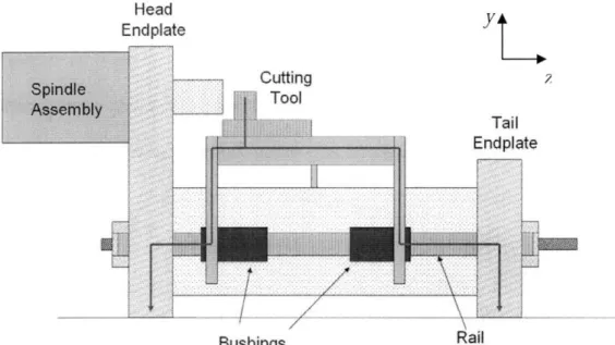
The endplates are made of cast aluminum while the structural tube between the caps is extruded aluminum. The steel rails bear the majority of the load during turning and facing operations and act as locating pins between the two endplates. As the spindle is driven and the cutting tool plunges into the work piece, forces on the cutting tool are transferred to the chassis via the tool holder, carriage, and either the carriage endplate or flexure, depending on which side of the lathe is under consideration. The two distinct load paths may be seen in Fig. 2.3 and Fig. 2.4. These figures illustrate how the load paths begin and end at same place, but travel through different components between the rails and the toolholder.
Head
Endplate
Yt
Bushings Rail
Figure 2.3: This schematic shows the cutting force load path from one side of the
lathe. On this particular side, the load is transmitted from the cutting tool to the carriage endplates and finally on to the chassis rails which transfer the load to the endplates and ultimately to the ground surface.
Wnrknipc 4
Figure 2.4: As in Figure 2.3, this diagram illustrates the cutting force load path as it
travels from the cutting tool through the carriage and flexure onto the lathe chassis and ground.
The structural tube between the endplates acts a as a housing for the leadscrew assembly and secures the ends of the chassis together. Structural tubes left over from the Spring 2007 semester of 2.72 were allocated for use in 2.75 in an effort to keep material and manufacturing costs down. This decision limited the design flexibility of the chassis and, as a result, from its first inception to present date, the chassis structure has changed very little. The majority of the work done on the chassis structure was focused upon the redesign of the endplates.
For the lathe components that were used in 2.72, the endplates were individually made from 1-inch thick billet aluminum and milled with a computer numeric controlled (CNC) mill. This method produced high quality endplates, but it was time consuming, costly, and required professional skills beyond the abilities of most students to complete. To address these issues, a standardized set of endplates were designed and cast at a local foundry. The sand casting process eliminated the need for billet aluminum and reduced the amount of material that was wasted in the manufacturing process. The cast pieces can be easily finished by using a Bridgeport EZ-TrakTM milling machine or equivalent readily available in most machine shops.
A finite element analysis using the CosmosWorksTM suite in SolidWorksTM was conducted in order to ensure that the endplates could safely handle the
maximum load they could potentially encounter in any turning or facing
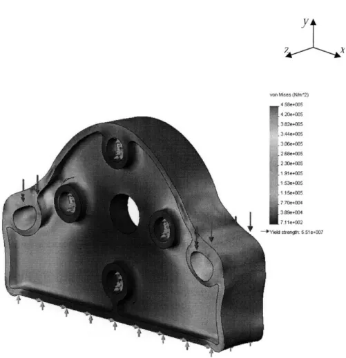
operations,. Figure 2.5 shows the Von Mises equivalent stress and safety factor for the tail endcap when a load of 375 N is applied to the bolt circles. This load is a
conservative estimate that was based on the maximum power of a 750-Watt DeWaltTM 36-volt cordless hammer drill and a 1" workpiece.
von Mises (NAn^2)
4 58e+005 4 20e+005 3.82e+005 3.44e+005 3.06e+005 2.68e+005 2.30e+005 1.91e+005 1.53e+005 1.15e+005 7.70e+004 3.89e+004 7.11e+002 Yield strength: 5.51e+007
Figure 2.5: These plots indicate a high factor of safety for the applied load.
This finite element analysis shows that the stress in the tail endplate is low and this component will survive this worst case scenario loading.
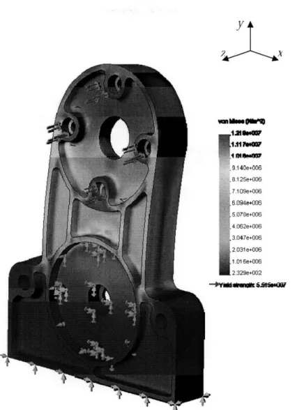
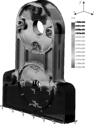
A similar analysis was conducted on the head endplate with comprable results. Figures 2.6 and 2.7 show that even when subjected to a worst case loading scenario, the head endplate survives with a factor of safety of over 4.
yJ~
Figure 2.6: From a worst case scenario loading cdndition, this von Mises
equivalent stress plot shows that the forces experienced by the head endplate are not enough to damage the part.
.11900 .9.1 40e+006 8.125e+006 7.109e+006 6.094e+006 5.078e+006 4.062e+006 3.047e+006 2.031 e+006 1.01 6e+006 2.329e+002 -)tilshmak S-SANlf
Figure 2.7: Above, the analysis indicates that the most conservative factor of safety
is approximately 4.5.
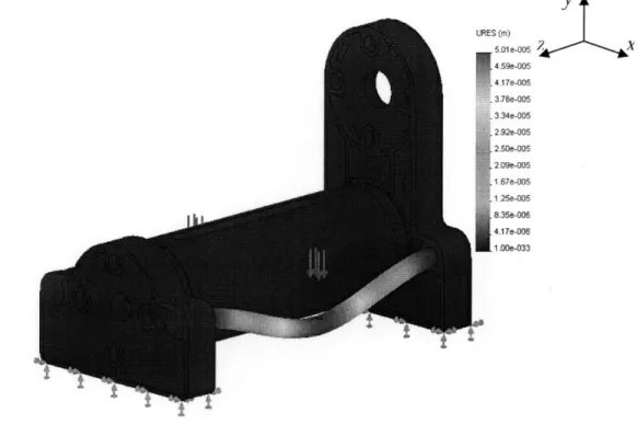
Another important consideration in the design of chassis components is the total deflection the combined members undergo when the lathe is operating. This is a critical value to identify because it ultimately drives the machine's static and dynamic accuracy. The simplified nature of this particular lathe design dictates that the rails on which the carriage rides must be particularly stiff to achieve a high structural loop stiffness. The load path diagram in Figures 2.3 and 2.4 make it apparent that throughout the length that the carriage travels, there is opportunity for significant bending stresses and deflections to manifest themselves in the rails. This
Y x mo=00 S183+001 22,+001 226a+001 4313+001 1355+001 339B+001 4119-001 248a+001 525a+00C
would result in bushing misalignment and, ultimately, binding. In order to
determine the overall chassis deflection, a representative load was applied directly to the rails in a CosmosWorksTM simulation. The rail deflection was calculated to be approximately 50 microns (0.002"). This deflection may be disregarded because it is an order of magnitude smaller than the allowable tolerance error of the chassis. Also, the load was determined using a conservative load. Figure 2.8 is a plot of CosmosWorksTM analysis leading to this result.
(M) 5.01e-005 4.59e-005 4.17e-005 3.76e-005 3.34e-005 2.92e-005 2.50e-005 2.09e-005 .67e-005 .25e-005 8.35e-006 4.17e-006 .00e-033
Figure 2.8: Although exaggerated for clarity in this figure, the deflection in the
rails for this overly conservative model is near 50 microns.
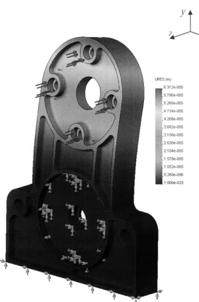
With rail deflection characterized, another source of deflection error must be considered. As the cutting tool plunges into the workpiece, a large force will be exerted on the bolted joint that attaches the spindle housing to the head endplate. This force causes a deflection in the head endplate along the z-axis of the lathe.
CosmosWorksTM predicts a deflection of 1 micron along the z-axis of the lathe. Figure 2.9 is a graphical representation of this deflection.
jIY
ES (m) 6.312e-005 5.786e-005 5.260e-005 .4.734e-005 .4.208e-005 3.682e-005 3.156e-005 2 630e-005 2.104e-005 1 .578e-005 1.052e-005 5.260e-006 1 .000e-033Figure 2.9: This plot of the total deflection of
the head endplate results in a very small deflection.
Combining the analyses above, it was determined that the total deflection in an extremely conservative scenario amounted to 113 microns (0.004"). For
accurate to just under 130 microns (0.005"). The deflection analysis conducted in this section establishes a baseline error value that limits the accuracy of the lathe. This model, however, does not account for any deflection in the carriage assembly, which will be discussed in a subsequent section.
2.2 Component Analysis: Leadscrew
Shifting focus to the carriage drive system may now be examined. Upon
reviewing various leadscrew assembly concepts that were generated by students in
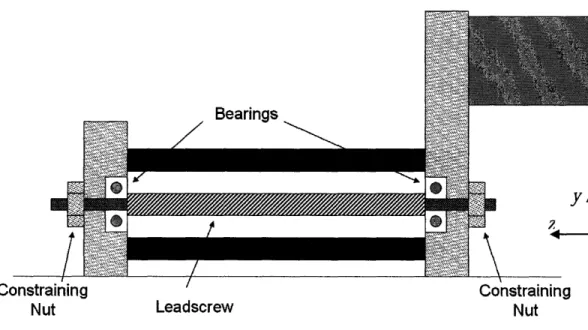
2. 72, some design and manufacturability concerns surfaced. The schematic
diagram shown in Fig. 2.10, illustrates a typical leadscrew constraint setup used in
2.
72
lathes.
Bearings Constraining Nut Leadscrew Constraining NutFigure 2.10: This is a leadscrew bearing setup typical of that created in 2.72. Most
lathes were designed with deep-groove ball bearings supporting the leadscrew. One student group used a nylon bushing in place of a ball bearing.
All of the lathes manufactured in 2.72 used deep-groove ball bearings or nylon bushings that were pressed into the endcaps. This configuration presents two major problems from a design and manufacturing perspective. For one, pressing the bearings into the endplates requires a tight tolerance between the bolt circle
connecting the chassis tube to the endplate and the fixed bearing pressed into the endcap. Bearings such as the ones used in this design require an alignment tolerance of 12.7 microns (0.0005")'. Errors in concentricity result in binding as the leadscrew turns. Considering that this kit is (1) to be designed for students who may have limited experience using a machine shop and (2) might not be
accustomed to manufacturing to tight tolerances, this design could lead to
frustrations and a negative learning experience. This particular design requires the use of thrust bearings between the constraining nut and the end caps. Although the face of the bearings on the inside of the structural tube can spin freely, when the constraining nut is tightened, friction between the nut and the endplate makes it difficult to spin the leadscrew. Figure 2.11 shows where this friction acts as the nut is tightened.
SOberg, Erik; Jones, Franklin D.; Horton, Holbrook L.; Ryffel, Henry H. Machinery's Handbook (27th Edition) & Guide to Machinery's Handbook. (pp. 2294). Industrial Press.
Frici
Constraining
Nut
Figure 2.11: This detail of Figure 2.10 shows the friction that prevents the leadscrew from spinning freely.
To resolve this issue, the design outlined in this thesis uses tapered roller bearings that support axial and radial loads. The tapered roller bearing allows for easier access to the leadscrew because the inner race may be removed without having to press the race off of the leadscrew.
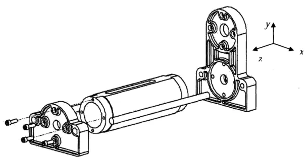
In this design, the leadscrew assembly is preloaded around an aluminum tube that sits within the structural chassis tube. The tube's axial position set by caps specifically designed to mate with the bearing tube. This design eliminates the problem of leadscrew misalignment. Figure 2.12 shows the assembly as it is constrained within the chassis tube. Figure 2.13 shows the chassis structure, bearing tube, and bearing tube locator assembly in an exploded view.
Bearing N Tube Tap Rc Beý p / Rubber Grommet Bearing Seat
Figure 2.12: An exploded diagram of the bearing tube assembly.
The bearing seats are used to locate the leadscrew radially within the
bearing tube. They also double as a preloading mechanism. ACME threads on the inner bore of the bearing seat provide a means of tightening the bearing seat against the inner race of the tapered roller bearings, thereby preloading the bearings. The grease cap and rubber grommets in the assembly prevent grease from traveling out of the enclosure as the leadscrew is driven.
C110400% ýa1eo* I>,n L 1
ýQ
-hc
Vs
4
adtshows the entire spindle assembly in an exploded view. The assembly shown below bolts directly onto the chassis head endplate once the module is fully assembled. This design is easier to assemble than many of the designs that were created in 2.72. They required that a bearing remain in the head endplate at all times. Much like the leadscrew assembly, the two nuts shown in Fig. 2.14, provide a way to preload the bearings against the races that are pressed into the housing.
I
pindle)usingCap
Figure 2.14: Above is an exploded view of the spindle assembly showing the
position of the taper bearings and preloading nuts within the housing.
Due to the tight tolerances that are required when machining surfaces that contact bearing races, the spindle assembly is the most difficult element of the lathe to fabricate. The spindle housing, which has the two outer races from the tapered
roller bearings pressed into it must be painstakingly machined in order for the bearing races to seat properly. Unfortunately, compromises with respect to bearing surface tolerances must be made if the module is to be manufactured within the LMP machine shop in a timely fashion. A compromise between tolerance and manufacturing time must be made because of two factors: (1) the lathes available in the LMP shop are manufactured to hold a maximum of a 130 micron (0.005 inch) tolerance at the chuck, and (2) the students in 2.75 and 2.72 may not have the
experience necessary to hold such a tight tolerance. Furthermore, maintaining concentricity between the spindle housing bearing seats require the use of a four-jaw chuck. Learning to use a four-four-jaw chuck is time consuming and outside of the
scope of 2.75 and 2.72. These issues manifest themselves as spindle runout errors in the final assembled lathe. A discussion of the spindle runout measured in a prototype of this lathe design may be found in chapter three.
The spindle is less of a challenge to manufacture because the overall diameter allows the student to use a collet when turning down the spindle profiles from round bar stock. Holding the round bar stock with a collet instead of a 3-jaw chuck reduces the amount of workpiece runout while turning down the spindle profile. Once a reference surface is turned on the spindle, the spindle blank can be
gripped by the collet along this reference surface. Using this method to turn the profile allows the student to turn both ends of the spindle while maintaining
concentricity between the ends of the spindle. The availability of shafts pre-ground to bearing surface tolerances further add to the convenience by eliminating the need to turn down a steel rod to size a reference diameter. Using a collet to turn down the spindle profile on a pre-ground shaft ensures that the ends of the spindle shaft remain concentric despite having been flipped 1800 during the turning process.
During turning and facing operations, the spindle shaft itself, which is essentially a beam cantilevered out past the second bearing, must resist deflection in order to maintain the highest possible accuracy when performing turning or facing operations. Assuming a worst case scenario load such as the one assumed for
previous chassis simulations, the calculations described below can be used to estimate the maximum deflection of the spindle.
From basic solid mechanics, the maximum deflection at the point of contact for a cantilevered beam is given by Eq. 1. The prototype shaft was made from an unhardened 1566 round steel bar that has a Young's modulus of 200 GPa.
Figure 2.15 outlines the parameters that are necessary to calculate the worst case scenario.
3
E
Eq. 1
3El
Eq.1Shaft Properties
Cantilevered Length, 1 0.038 m (1.5 in)
Diameter, d 0.0254 m (1 in)
Young's Modulus 200 GPa (116 Kpsi)
Second Moment of Area, I 2.04 x1 a8 m4 (0. 049 in4)
Load Applied 391 N (88 IbI)
Figure2 .15: This table identifies the material and geometric properties of the steel
spindle.
6 = 46.1microns (0.0018")
This is the maximum the spindle could ever deflect given the power of the driving mechanism. Restricting the materials to be turned on the lathe to aluminum or any softer metal will prevent this deflection from ever occurring because of the lower energy required to turn aluminum stock.
2.4 Component Analysis: Carriage
This redesigned lathe carriage remained almost largely unchanged from the design that was generated for 2.72. Several designs for one-piece sand cast
carriages were generated and analyzed in the course of the research. The design and analysis of the carriage was conducted in full anticipation of casting the carriage piece. Creating a pattern for this casting, however, required more time than was available. Thus, no cast carriage design was able to transition from solid model to physical lathe component. The redesigned carriage that emerged from this
research is shown in Fig. 2.16. Y
X42
Figure 2.16: The proposed carriage design shown above never came to fruition due
to financial and time limitations. This particular design replaces three individual components with one cast piece.
The main problem with nearly every one-piece design was the issue of manufacturability. In trying to keep the manufacturing costs down, a significant amount of research effort went into identifying a feasible pattern manufacturing process. This occurred under tight time constraints as the design was needed for the
Fall 2007 semester of 2.75. Design compromises were unavoidable. Options such as stereolithography, direct rapid metal manufacturing and handmade wooden
patterns were considered but eventually deemed impractical or too costly to pursue within the short timeframe.
The course objectives in 2.75 revolved primarily around flexure design, particularly the flexure design of the lathe's cross-slide assembly and the leadscrew-carriage connection. The leadscrew-carriage design requirements included the need for a flat mobile bed with adequate mounting space for a flexure that could (a) hold a cutting tool on the top side and (b) possessed mounting space for a leadscrew flexure on the underside.
A significant amount of effort was expended in the selection of the bronze bushings for the carriage endplates. The choice was primarily driven by the experience of working with the 2.72 lathes which used a variety bushing materials. The design of the carriage rails specified a rail diameter of 0.0127 m (0.5"). Using bushing size guidelines from the Machinery's Handbook2 and Marks'Standard
Handbook for Mechanical Engineers3, a bushing with a with a 0.0032 m (0.125")
wall thickness and a length of 0.038 m (1.5") was selected. An exploded diagram of the carriage assembly may be seen in Figure 2.17.
2 Oberg, Erik; Jones, Franklin D.; Horton, Holbrook L.; Ryffel, Henry H. Machinery's Handbook
(27th Edition) & Guide to Machinery's Handbook. (pp. 2235). Industrial Press.
3 Avallone, E.A.; Baumeister, T., III (1996). Marks' Standard Handbook for Mechanical Engineers
Figure 2.17: This carriage design was developed and used for 2. 72 in the Spring of
2007 and for 2.75 in the Fall of 2007.
The flexure shown in the figure 2.16 was also developed in 2.72 using a flexure analysis program known as CoMeT. The flexure is designed to allow for leadscrew eccentricities and to correct for any misalignment in the guide rails. Design details pertaining to this flexure have been omitted because this leadscrew flexure is not included in the lathe kit.
Chapter 3
Testing
Measurements of carriage rotation about the z-axis and x-axis, known as carriage roll and pitch respectively, were taken using a coordinate-measuring machine (CMM) that was capable of measurement at a resolution of 5 microns (0.0002 in). The CMM was also used to measure the spindle runout. These
measurements were taken in order to test the accuracy of the fully assembled lathe.
~aap
TI1;Sn:
3.1 Test Setup
To determine the pitch and roll of the carriage, the y-axis position, or height,
of specific points on the lathe carriage were measured as the carriage traveled along
the z-axis. A schematic of the measurement points used may be seen in Figure 3.1.
The measurements of interest were taken at two points on opposite ends of the
carriage as the carriage traveled along the z-axis in order to determine the change in
height with respect to the baseline height measurements. The baseline height
measurements were defined as the height of the carriage measurement points at one
extreme of the carriage's travel. As the lathe moved along the z-axis, the carriage
was stopped periodically and the coordinates of the measurement points were
documented. The lathe carriage was stopped at five points as it traveled along the
z-axis.
2t
Figure 3.1: This illustration shows the measurements taken to determine the
overall pitch and roll of the carriage as it travels down the z-axis of the lathe.
Measurements of spindle runout were taken by measuring the top of the spindle at eight angular intervals as the spindle was rotated to a static position.
Figure 3.2 shows the measurement points on the spindle. Like with the carriage roll and pitch, the spindle runout was determined by measuring the change in y-axis position of the measurement points as the spindle completed one revolution.
Runout Measurement
Dlindr
y
A77,
Figure 3.2: This schematic shows the method used to measure the spindle runout.
3.2 Results
The results showed a maximum carriage y-axis error of 40 microns (0.015") as the carriage traveled down the z-axis of the lathe. These results are summarized in Fig. 3.3.
Carriage Pitch
y-Axis Measurement
Height
ex
m (in) Difference milli-radians Point A Point B microns (in) (degrees)
0.15989
0.11574
246
1.58
(4.5665) (4.5568) (0.0097) (0.00154)0.11600
0.11564
361
2.32
(4.5672) (4.5530) (0.0142) (0.1328) 0.11602 0.11565 365 2.35 (4.5676) (4.5532) (0.0144) (0.1347)0.16019
0.11566
363
2.34
(4.5677) (4.5534) (0.0143) (0.1337) 0.11603 0.11566 378 2.43 (4.5683) (4.5534) (0.0149) (0.1394) Carriage Rolly-Axis Measurement
Height
ey
m (in) Difference milli-radians
Point A Point B microns (in) (degrees)
0.11605 0.115722 325 4.26 (4.5688) (4.5560) (0.0128) (0.2444) 0.11606 0.115722 340 4.46 (4.5694) (4.5560) (0.0134) (0.2560) 0.11605 0.115725 332 4.37 (4.5692) (4.5561) (0.0131) (0.2502) 0.11605 0.115727 322 4.23 (4.5689) (4.5562) (0.0127) (0.2425) 0.11602 0.115735 287 3.77 (4.5678) (4.5565) (0.0113) (0.2158)
Figure 3.3: The results made with a CMM.
above show that the carriage pitch and roll measurement
The results of the spindle runout measurements showed that the end of spindle moved along the y-axis as it rotated about the z-axis. The amount of total runout measured was 160 microns (0.0063"). The spindle runout measurements made at each point along the z-axis rotation are summarized in Fig. 3.4.
Figure 3.4: This figure compares the measurement of spindle points throughout the rotation of the spindle.
height at various
3.3 Error Sources
The carriage errors shown in Figure 3.3 are smaller than the maximum errors allowed. The allowable error is determined by calculating the pitch and roll of the carriage under a worst-case manufacturing scenario. The table in Figure 3.5 compares carriage pitch and roll calculated when lathe chassis is manufactured with the highest dimensional error allowed by the tolerances specified in the part
drawing. These drawings may be viewed in Appendix A.
Spindle Runout
Point Measurement Total Runout
Point
m (in) microns (in)
0.16048 (6.3181) 0.16047 2 0.16047 (0.00005) (6.3176) 3 0.16046 (0.00160) (6.3165) 4 0.16035 (0.00510) (6.3130) 50.16031 (0.00630) (6.3118) 6 0.16033 (0.00560) (6.3125) 70.16039 (0.00320) (6.3149) 0.16047 8 0.16047 (0.00004) (6.3177)
Figure 3.5: A comparison of calculated and measured carriage pitch and roll.
The concentricity error that was measured has no calculated counterpart because none was specified in the part drawings. Controlling concentricity is difficult to do with the tools available to students and is beyond the scope of the course. Sources of the concentricity error measured in the test are discussed in the next chapter.
Chapter 4
Summary
This thesis presented the redesign and characterization of an educational kit for the mechanical engineering courses 2.75 and 2.72. The purpose of this thesis was (1) to produce a kit that would fall within the scope of a senior and graduate level courses such as 2.75 and 2. 72, (2) generate a design that would give the students an opportunity to innovate, (3) provide instructors with the flexibility to adapt their curriculum around the lathe, and (4) create a project that would interesting enough to stimulate student interest in the subject.
Maximum Roll and Pitch
Error Comparison
Calculated
Measured
milli-radians
milli-radians
(degrees) (degrees)3.26
2.43
(0.1871) (0.1394)6.67
4.46
(0.3820) (0.2560)The efforts entailed in this thesis are important because better educational tools provide students with a more productive learning experience. Having a better learning experience will impact the mechanical engineering department and the world by producing better engineers.
Two student groups chose to use the lathe kit during the the Fall 2007 semester of 2.75. Both groups completed the design project and one group adapted the kit with computer numeric control (CNC) capabilities. The fact that both groups created a fully functional lathe on time and with only minor necessary modifications indicates that the project was within the scope of a precision engineering course. Additionally, adding CNC capabilities to the kit lathe is an indication that student interest was piqued and student innovation was facilitated. The goal of course flexibility was reached by the modular design of the lathe. To summarize, these are the contributions made towards achieving the aforementioned goals:
1. The evaluation of existing table-top lathes produced in the Spring 2007semester of 2.72.
2. The design and analysis of a standardized lathe chassis that was less expensive to manufacture than prior versions and provided interfaces that mate with the other lathe modules.
3. The design of a modular leadscrew assembly that does not depend on the lathe chassis for structural support during preloading.
4. The design of a modular spindle assembly that (1) uses a factory ground shaft to minimize concentricity errors during fabrication and (2) uses tapered roller bearings with preloading nuts threaded
directly on to the shaft to isolate the assembly from the lathe chassis. 5. The design of a one-piece sand-cast lathe carriage.
6. The fabrication and testing of a prototype lathe to determine the feasibility of manufacture as well as dimensional accuracy of the lathe.
4.1 Future Work
The experience of manufacturing a prototype for testing purposes led to some suggestions for future work.
First is the issue of improving the surface finish of the spindle. The steel used for the prototype was 1566 alloy steel. This steel was difficult to machine and left a very poor surface finish. Switching to a softer steel would improve the finish, but analysis must be conducted to prevent failure.
The second suggestion for future work is the inclusion of spring washers to pre-load the tapered roller bearings used in the lathe. Unfortunately, the threads on the spindle and leadscrew were too coarse to control the amount of preload on the bearings. The use of spring washers between the bearing race and preload nut would improve this control.
Appendix A
A tolerance analysis was conducted with the following drawings to determine the predicted maximum value of carriage roll and pitch.
i2.75
Lathe End Cap
OESIGERý M. Lopez (480) 650 8782
DATE: 0710312007
SCALE
11
0 020 0MATL:Cast LAl
REVISION: A i x•, 0%, ohttpi/pcsl.mit.eduProperty of the MIT Precision Compliant Research Lab. The contents of this document are proprietary I1 and only for use by MIT and its authorized partners. LL J
c ci c-0J 1.938 c0 If3 Li) b-,j ¢'
Appendix B: Finite Element Force Calculations
Below are the calculations used to determine the force used in the finite element analysis of the chassis module. All calculations assume a 0.0254 m (1") workpiece.Drill Max Power Cutting speed (Al) Diameter Cutting Torque Cutting Force
P= co *r
P r = 9.5 N*m t= F x d F=375 N P-750 Watts4 )=750 rpm5 d--0.0254m F (la) (lb)4 Dewalt.com. Dewalt Industrial Tool Co.,
<http://www.dewalt.com//us/products/too_detail_print.asp?productlD=-14926>
5 Oberg, Erik; Jones, Franklin D.; Horton, Holbrook L.; Ryffel, Henry H. Machinery's Handbook (27th Edition) & Guide to Machinery's Handbook. (pp. 1038). Industrial Press.