DIGITAL FABRICATION IN THE
ARCHITECTURAL DESIGN PROCESS
byJennifer CK Seely
Bachelor of Architecture University of Arizona
May 2000
Submitted to the Department of Architecture in partial fulfillment of the requirements for the degree of Master of Science in Architecture Studies at the
Massachusetts Institute of Technology June 2004
0 2004 Massachusetts Institute of Technology. All rights reserved.
-ep'artment'6f Architecture May 19, 2004 Certified By Accepted By MASSAHUEUS INSn ET OF TECHNOLOGY
JUL 0 9 2004
LIBRARIFS
--- --- --- - -- - - - --.- - .- .-. ... ---.. .. . .----Lawrence Sass Assistant Professor of Architecture Thesis Supervisor...--... . .-. ...- - - - ---.. ---.---- -- --.-- .
--. jlian Beinart Professor of Architecture Chairman, Department Committee on Graduate Students
ROTCH
Signature of AuthorTHESIS COMMITTEE
Lawrence SassAssistant Professor of Architecture Thesis Supervisor
William L. Porter
Norman B. & Muriel Leventhal Professor of Architecture & Planning Thesis Reader
Tim Eliassen
President of TriPyramid Structures, Inc. Thesis Reader
DIGITAL FABRICATION IN THE
ARCHITECTURAL DESIGN PROCESS
byJennifer CK Seely
Submitted to the Department of Architecture on May 19, 2004 in partial fulfillment of the requirements for the degree of Master of Science in Architecture Studies
ABSTRACT
Digital fabrication is affecting the architectural design process due to the increasingly important role it has in the fabrication of architectural models. Many design professionals, professors, and students have experienced the benefits and challenges of using digital fabrication in their design processes, but many others in the field are not yet aware of the possibilities and drawbacks afforded by these technologies. The research presented here unveiled key issues on the matter through a series of interviews with twenty-five individuals, focusing on digital fabrication in their practices and schools, and through three experiments utilizing eight digital fabrication methods, such as three-dimensional printing, laser cutting, and desktop milling. The interviews and experiments form a basis for suggesting better ways to utilize current digital fabrication methods in design and for proposing future methods better suited for the architectural design process.
Thesis Supervisor: Lawrence Sass Title: Assistant Professor of Architecture
ACKNOWLEDGMENTS
I wish to express my most sincere gratitude and appreciate to the many people who have played a significant role in my education and work. My advisor, Larry Sass, for his continuous guidance and support. This thesis would not have been possible without him.
My reader, Bill Porter, for his wisdom and trusted counseling.
Tim Eliassen, also my reader, for his enthusiasm and for keeping me grounded.
The Center for Bits and Atoms, for funding my research position with Larry Sass and providing me with access to the Fabrication Lab. I am indebted to all those I interviewed, for their time and assistance. I learned the most from them in this thesis. It could not have been possible without them. My deepest thanks to Charles Blomberg, Joshua Katz, Paul Kempton, Kurt Komraus (especially Kurt, for the many hours he spent with me), Paul Koontz (and Grace Nugroho, my friend, for getting me in touch with Paul), Jim Maitland, Rolando Mendoza, Julian Palacio, Caroline Smogorzewski, Kirk Alcond, Fernando Domeyko, Mark Goulthorpe, Earl Mark, John Nastasi, Daniel Schodek, Jan Wampler, Charles Austin, Josh Barandon, Carlos Barrios, Joseph Dahmen, Talia Dorsey, Han Hoang, Jelena Pejkovic, Alexandra Sinisterra, and Alexandros Tsamis.
John Difrancesco, Tom Lutz, Thom Allwood, and Tom Berezansky, for their help and patience in the Fab Lab.
Sarah Hudson, for months of hard work, help, and fun with the experiments.
Michael Mulhern, for trusting me and teaching me.
Renee Cheng, for her mentorship and assistance. All of my professional and scholastic work stems back to her.
Michael Samra, for his friendship, support, and trust.
John Rappa, "Duke" Duchnowski, Big Bob, Little Bob, Keith, Dave, and Bill, for their friendship and for teaching me how the manufacturing process really works.
Dave Dow and Pat McAtamney, for their guidance in 2.008 and helping me understand more about CNC processes.
Thalia Rubio at the MIT Writing Center, for her advice on my writing. My SMArchS classmates, especially Alexandra, Rita, and Keru, for their consistent support and friendship.
My grandparents, Nana & Pa and Grandma & Grandpa, for their support and love.
Laurie, my sister, for keeping in touch with me these last two years and simply for being my sister.
My Dad, for believing in me and loving me.
My Mom, for helping me tremendously with my writing and for her love and support. I enjoyed having her be a part of this.
Most of all, I thank my husband, Jason, for all the years of love, encouragement, friendship, and advice he has have given me. It is a privilege to have him in my life and a pleasure to share this with him.
TABLE OF CONTENTS
PREFACE CHAPTER 1: INTRODUCTION 1.1 Background 1.2 Methodology CHAPTER 2:CURRENT DESIGN AND FABRICATION PROCESSES 2.1 Physical Representation of Architectural Designs
2.1.1 Model Types
2.1.2 Handmade Model Making 2.1.3 Digital Fabrication:
Computer Numerical Control and Rapid Prototyping
CHAPTER 3:
SURVEYING THE ARCHITECTURAL DESIGN FIELD 3.1 Primary Issues Unveiled
3.1.1 Differing Design Processes
3.1.2 Cost Issues and Evolving Technologies 3.1.3 Favored Machines
3.1.4 Most Influential Machine
3.1.5 Misleading Fabrication Processes 3.1.6 CNC Milling Challenges
3.1.7 Importance of User-Friendliness 3.1.8 Significance of Physical Representation
CHAPTER 4:
EXPERIMENTING WITH DIGITAL FABRICATION 4.1 Experiment 1:
Fused Deposition Modeling of Self-Assembled Domes 4.2 Experiment 2:
Digital Fabrication of Self-Assembled Joints 4.3 Experiment 3:
CHAPTER 5:
COMPARATIVE ANALYSIS 5.1 Benefits and Challenges 5.2 Common Misconceptions 5.3 Effects on the Design Process
CHAPTER 6: CONCLUSIONS
6.1 Suggestions and Cautions for Today's Machines 6.2 Outlook on Tomorrow's Machines
6.3 Speculative Remarks BIBLIOGRAPHY
APPENDIX Appendix A:
People Interviewed in Survey A. 1 Professionals
A.2 Professors and Supervisors A.3 Students
Appendix B:
Benefits and Challenges of Digital Fabrication Machines B.1 Roland CAMM-1 Vinyl Cutter
B.2 Roland Modela MDX-20 Milling Machine B.3 Denford Micromill 2000
B.4 Stratasys FDM 2000
B.5 Universal Laser Systems X-660 Laser Platform B.6 Z Corporation ZPrinter 310 System
bundled with the ZD4i Depowdering Station B.7 HAAS Micro Milling Center
PREFACE
My understanding of the tectonics of architecture grew during my undergraduate education with the help of my professor and mentor, Renee Cheng. By graduation I was very interested in the designing and manufacturing of architectural details, and how the details relate to an overall architectural design. In July 2000 I began working for Tim Eliassen and Michael Mulhern at TriPyramid Structures, an architectural component design and fabrication company.
I was directly involved in the designing, manufacturing, and assembly of architectural details during my time there. I learned the concepts of many different types of manufacturing methods, such as creating digital files which were used by waterjet and laser cutting manufacturers. I sat adjacent to the shop where parts that I drew were being manufactured. It was an entirely different level of design than I
had been taught in school.
I worked there for a little over two years before I went back to school. My interests in tectonics and my recent experience at TriPyramid influenced what I chose to do at MIT. I took Larry Sass's Design Fabrication workshop, where I was introduced to various digital manufacturing machines, and John Fernandez's Emergent Materials workshop, which introduced me to various types of materials. I participated in an undergraduate Mechanical Engineering course, Design & Manufacturing II, where I gained hands-on experience with full-size CNC milling machines, CNC lathes, injection molders, and vacuum formers. I also taught an undergraduate class where I trained students how to prepare digital files for the laser cutter and three-dimensional (3D) printer. In addition to these classes, I was fortunate enough to work as a Center for Bits and Atoms research assistant in Larry's Digital Design Fabrication Group. Through the work I did for the group I gained an extensive amount of hands-on experience with a range of digital fabrication machines, which allowed me to teach students how to use these machines in two more of Larry's workshops.
As time went on I saw that there was a growing interest in digital fabrication among students, both in and out of studios. It appeared to me that each of these machines embodies different qualities and fits into schools and offices in different ways, some having more relevancy than others in the design process. Equipped with my professional and research experience, I felt I was in a good position to evaluate the state of digital fabrication in the architectural design process.
CHAPTER 1:
INTRODUCTION
Various types of digital fabrication machines are working their way into architecture schools and offices, slowly being integrated into the array of tools architects utilize to create physical representations of their designs. These fabrication technologies were developed for professions other than architecture, such as industrial design and mechanical engineering, so when architects start to use them they are forced to conform to other ways of working that may not be natural in the architectural design process. These technologies are having positive and negative effects on the design process as more architects and students integrate digital fabrication methods into their model making processes. Now is the time to step back and address what these effects are in order to understand how architects can better use the machines that are currently available. This thesis also proposes the attributes future digital fabrication machines should embody in order to be better suited for use in the design phases of architecture.
1.1 Background
Digital fabrication is defined as computer-aided processes that manipulate material through subtractive or additive methods. These processes can be broken down into two groups: computer numerical control (CNC) processes and rapid prototyping (RP) processes. The fundamental difference between these two is that the CNC processes create objects by removing material (subtractive) while RP processes create objects by building it up layer-by-layer (additive). A few examples of CNC processes are milling, waterjet cutting, and laser cutting. RP processes include three-dimensional printing, stereolithography, and fused-deposition modeling.
Researchers began contemplating the "automatic model shop"' thirty years ago when they became aware of the possibilities provided by
1 William M. Newman and Robert F. Sproull, Principles ofInteractive
Fig. 1. Physical model of object constructed from computer model with numerically controlled
machine, Principles of Interactive
Computer Graphics (USA: McGraw-Hill, 1979) 299.
Fig. 2. Model of Le Corbusier's building in the Weissenhofsiedlung generated by stereolithography, "Creating Architecture Models by Computer-Aided Prototyping," Proceedings of the 21' ICAAD, 1991.
computer-aided milling machines (fig. 1). In 1977, Mitchell wrote that by "interfacing production machinery with computer graphics systems, a very sophisticated design/production facility can be developed".2
Technology progressed, and by the 1990's there was an extensive body of research conducted by Bernd Streich at the Department of CAAD and Planning Methods at the University of Kaiserslautern in Germany. He wrote numerous papers and a book on the topic of computer-aided techniques for fabricating physical models. In 1991 he introduced the use of stereolithography, one of the only RP techniques available then, as a feasible method for building architectural models (fig. 2). In 1996
he co-authored a book titled Computergestitzter Architekturmodellbau
[Computer-Aided Architectural Model Building], which was the first complete work to describe the topic of digital fabrication in the architectural design process.3 Alvise Simondetti's 1997 Master's
thesis, titled Rapid Prototyping in Early Stages of Architectural
Design4, addressed how digital fabrication could be used to make
architectural models. In his thesis, Alvise teaches the reader 25 frequent mistakes made by a designer when he or she attempts to use these technologies. In 2002, researchers in the Rapid Design and Manufacturing Group at the Glasgow School of Art published a paper discussing the applicability of RP techniques in the field of architecture.' Even more recently, Breen, et al. at the Delft University of Technology published an article describing how CNC milling machines, laser cutters, and three-dimensional printers can be utilized
2 W. J. Mitchell, Computer-A ided Architectural Design (New York: Wiley, John & Sons, 1977) 372.
3 Bernd Streich, Computergestitzter Architekturmodellbau (Basel: Birkhiuser,
1996) 4
Alvise Simondetti, "Rapid Prototyping in Early Stages of Architectural Design", Master of Science Thesis, MIT, 1997.
5
Gerard Ryder, et al., "Rapid Design and Manufacture Tools in Architecture," Automation in Construction 11 (2002)Fig. 3. 3D printed house (scale
1:100) from plaster-based powder, "Tangible virtuality-perceptions of computer-aided and physical modelling," Automation in
Construction 12 (2003) : 651.
in the architectural model-making process (fig. 3).6 Since then, prices have come down and these digital fabrication machines have found their way into even more schools and offices. As these machines become more common in the field, designers, professors, and researchers are exploring new methods of designing, teaching, and working with digital fabrication.7 Now that designers have had the
chance to integrate these fabrication processes into their model building techniques, I am stepping back to analyze how this new way of working is affecting the design process.
1.2 Methodology
In order to fully understand the topic of digital fabrication in the architectural design process, I needed to couple my knowledge gained through research and practice with others' observations. This research unveils key issues on the matter through a series of interviews with twenty-five individuals focusing on digital fabrication in their practices and schools and through three experiments utilizing eight digital fabrication methods. These interviews and experiments form a basis for suggesting better ways to utilize current digital fabrication methods in design and for proposing future methods better tailored to the architectural design process.
This investigation brought many important issues to the surface regarding the use of digital fabrication methods such as the designer's sensitivity to cost, time, and user-friendliness. Physically representing an architectural design can be done in many ways, but the cheapest, quickest, and easiest methods will always prevail.
6 Jack Breen, Robert Nottrot, and Martijn Stellingwerff, "Tangible Virtuality
-Perceptions of Computer-Aided and Physical Modelling," Automation in Construction 12 (2003)
7 See the Bibliography: Bechtold, et al., Broek, et al., Burry, Chaszar and Glymph, Ham, Kolarevic, Mald-Alemany and Sousa, Mark, Modeen, Pegna,
CHAPTER 2:
CURRENT DESIGN AND FABRICATION
PROCESSES
Every designer has a slightly different design process from the next, yet we all generally work in the same general-to-specific manner. Usually a professional designer or student begins with a conceptual idea, extensively refines it, and eventually arrives at a final design he or she feels solves the problem in an appropriate manner. At the same time, the design processes found in the educational world versus the professional world of architecture vary quite drastically. Ultimately, each group is designing with a different goal in mind. The architect's ultimate goal is to construct a full-scale building, while the student's goal is to construct a smaller-scale, physical representation of a building. Students have a different palette of model-making tools than professionals. This is significant because "Architects tend to draw what they can build, and build what they can draw."' If students are building for a RP machine and professionals are building for a steel manufacturer's machine, the designs between the two groups are going to be different. This chapter provides an overview of the most common physical representation types used in the architectural design process and the fabrication methods used to create them.
2.1 Physical Representation of Architectural Designs
Many different forms of representation in the architectural design process exist, ranging from digital to physical, and from two-dimensional to three-two-dimensional. Sketches, drawings, renderings, animations, and physical models all help to portray the designers' ideas to another person. Whether it is a student conveying an idea to a professor, an architect presenting a design to a client, or an architect providing building instructions to a contractor, representation is a key part of the architectural design and construction process. Among these
8 William Mitchell, "Roll Over Euclid: How Frank Gehry Designs and Builds," Frank Gehry, Architect (New York: Guggenheim Museum Publications, 2001) 354.
forms of representation I focused on physical models, which serve many different purposes in the design process. They help designers generate new ideas, represent their ideas to others, and test the behavior of full-size building components. In this section, I will present the different types of physical representations that can be found in the field and the different methods for making these models.
2.1.1 Model Types
I would like to review five different levels of architectural modeling found in schools and offices. In their paper, Rapid Design and Manufacture Tools in Architecture, Ryder, et al. describe three typical levels of modeling drawn from interviews and a literature survey. The three model types they found are: the feasibility model, the planning model, and the final project model. In addition to these three, I found two more levels of modeling through my survey that I would like to add to the list: the abstract model and the full-scale mockup.
Ryder, et al. describes the feasibility model as an object typically used to convey the concept of the building design. Not much detail is added and the size is usually small, yet it is starting to take the general shape of an architectural form.
The planning model is used when a little more detail needs to be conveyed at a slightly higher quality than the feasibility model. The designer can portray a more clear understanding of the building design
and its relationship to its context.
The final project model shows what the project will look like once it is completed. In practice, this is the type of model that is shown to clients and the public. In school, this is the model shown at a final design review to portray the final design intent.
Fig. 4. X-Acto knife and blade.
The abstract model is commonly used for abstract form or space studies. This type of model is often created to present the "sensibility"9 of a design in the earliest stages of the design process.
Full-scale mockups are occasionally needed in practice to test the final behavior of a certain set of assembled building components. Fabricated at the full scale, these models allow the designer to verify the final form and functionality of the chosen assembly. Students are sometimes required to build small mockups in school in order to experience how real, full-sized building materials perform.
The fabrication methods that are used to create architectural models can be split into two groups: handmade model making and digital fabrication. The handmade methods are presented purely as a
reference. I will elaborate more on the digital fabrication methods in order to prepare the reader for discussions in subsequent chapters.
2.1.2 Handmade Model Making
When employing one of the many methods of handmade model making, the designer has immediate control of the tool's manipulation of the material. A wide range of tools can be used to create architectural models by hand and each tool typically has a limited group of materials that can be manipulated by it.
Handheld tools used for making architectural models include scissors, X-Acto knives, utility knives, hacksaws, chisels, files, and sandpaper (fig. 4). Scissors, a tool everyone is familiar with, cut thin sheet materials such as paper, acetate, foil, rubber, and foam. X-Acto and utility knives are used when highly controlled cuts are needed or when the material is thicker or slightly harder. Chipboard, cardboard, foamboard, bass and balsa woods, and thicker foils can be manipulated with these knives. They can also sculpt woods, foams, and clay. Saws are best used when even thicker, harder materials need cutting such as
larger wood sticks, small aluminum or copper members, or extruded plastic members. Chisels, files, and sandpaper are used for finishing the edges and surfaces of model materials.
Conventional machines can be categorized as another group of tools used in handmade model making. These machines have been around for decades and are a common part of any shop. Instead of the user guiding a handheld tool, the user guides the material through the machine. These machines include different types of saws, drill presses, milling machines, routers, lathes, grinders, and sanders. Table saws and routers are used to cut large, flat sheets of material such as woods, plastics, and foams. Band saws and chop saws are used to cut smaller, more manageable pieces of the same types of materials. Drill presses are used to drill holes in almost any material of a manageable size. Milling machines and lathes are used to subtract material from standard blocks or rods of metal, wood, plastic, plaster, or foam. Grinders and sanders are typically used to clean up the edges and surfaces of various materials.
In addition to all of these tools and machines, a person's hands should also be considered as tools. They are involved with all of the hand-made model-making methods and can manipulate materials on their
own without being limited to a certain group of materials. Not only can hands bend, fold, and tear materials, but they can add materials together through sculpting clay or gluing materials together. It is the only tool I have mentioned so far that manipulates materials in an additive fashion. The only other set of tools that build objects in this fashion are the rapid prototyping machines, which will be presented in section 2.1.3.
All of these handheld tools and conventional machines have been used for decades in architectural model making. Every architecture school and many offices have their own model shops consisting of many of these tools and machines. Only within the last few years have digital
Fig. 5. Roland Modela MDX-20 desktop milling machine.
Fig. 6. Rigid foam being milled on the Modela MDX-20 milling machine.
Fig. 7. Denford Micromill 2000 desktop milling machine.
fabrication machines started to join the group of well-utilized, model making tools in architecture.
2.1.3 Digital Fabrication:
Computer Numerical Control and Rapid Prototyping
When employing digital fabrication methods in the model making process, the user has almost no control of the tool at the moment it is manipulating the material. All digital methods start by the user setting up a file in the computer and end by the user sending the file to the machine. The user has varying amounts of control over the manipulation of the material during set up, but once the file has been sent, the user can do little but watch. There are rare exceptions where some machines allow the user to slow down or speed up the process of manipulation, but never the manipulation itself.
The digital fabrication methods I will focus on throughout the rest of this thesis can be split into two groups: computer numerical control (CNC) processes and rapid prototyping (RP) processes. The fundamental difference between these two is that the CNC processes all work through subtractive methods of manipulating material to create the final object, while all RP processes utilize additive methods of building up material layer-by-layer.
One should keep in mind that all of these processes were originally developed for use in industrial design and manufacturing. Machines designed for use in industrial shops are typically difficult for an architect or student to use because there are too many factors that must be considered for a novice to efficiently operate on his or her own. However, many of these processes have been compacted into smaller, more user-friendly machines that are more suitable for architecture offices and studio environments. This has made it easier for designers to use the machines in architectural model making.
Fig. 8. HAAS Super Mini Mill.
Fig. 9. Precix Industrial Series 9100 4'x8' table router.
Fig. 10. OMAX Waterjet Machining Center.
Fig. 11. Waterjet cutting example.
CNC Processes
All of the fabrication methods I am categorizing as CNCprocesses create objects by removing material from a starting block, rod, or sheet through computer controlled movements. The user starts the process by preparing a file in the computer, sets up the material in the machine, and then sends the file to the machine. The machine automatically mills or cuts the material according to the computerized directions it is given. I will briefly present the five most common CNC processes that are used in the architectural design process. More detailed information is discussed in Manufacturing Engineering and Technology (Kalpakjian and Schmid, 2000).
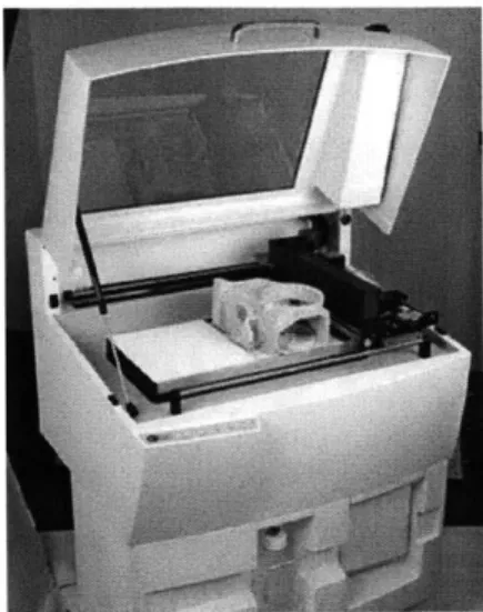
CNC milling is used to create forms from blocks of materials such as woods, metals, plastics, and foams. These machines come in a variety of sizes. The MIT Department of Architecture has two desktop CNC milling machines, the Roland Modela MDX-20 (figs.
5 and 6) and the Denford Micromill 2000 (fig. 7). I also had access to a larger, industrial-sized HAAS Super Mini Mill (fig. 8) milling machine, which I could not run without the assistance of a well-trained operator. This fabrication process is most useful for creating small, singular architectural components.
A similar digital fabrication process is CNC Routing, which works in a similar fashion to milling except it is meant to cut large, flat, sheet materials versus smaller, block materials (fig. 9). Many architecture schools have table routers, such as the Precix 9100 in their shops due to the router's applicability in creating large site models or other complex forms from materials such as large plywood or foam sheets.
CNC waterjet machining is also used to cut large, flat sheets of material. An advantage the waterjet cutter has over the table router is the wide spectrum of materials it can cut. In addition to
Fig. 12. Universal Laser Systems X-660 Laser Platform.
Fig. 13. Laser cutting example.
Fig. 14. Roland CAMM-1 vinyl cutter.
Fig. 15. Roland CAMM-1 vinyl cutter.
plywood and foam, it can cut metal, stone, glass, rubber, composite materials, and many more. As a part of the Center for Bits and Atoms, I was able to use the center's OMAX 2652 waterjet cutter (figs. 10 and 11).
Like CNC milling machines, laser cutters also come in a variety of sizes, ranging from desktop to shop-sized machines. The MIT Department of Architecture has an Universal Laser Systems X-660 laser cutter (fig. 12), which can cut sheets of material up to 18"x32". Universal Laser Systems also provides desktop laser platforms that are cheaper and more suitable for small offices. Laser cutters typically cut thin, sheet materials such as wood, paper, chipboard, museum board, cardboard, foamboard, and plastics (fig. 13).
The fifth CNC machine is the Roland CAMM-1 vinyl cutter, which cuts very thin sheets of vinyl, paper, acetate, and foil with a small blade (fig. 14). Creating precise, smooth cuts is its greatest advantage (fig 15).
Many other CNC processes exist; however, the five that I have mentioned are the most useful in the architectural design process. CNC plasma cutting, wire cutting, turning, and turret punching are some of the many other processes currently available. The prices of CNC machines currently run between $2,000 and $500,000.
Rapid Prototyping
All of the fabrication methods I am categorizing as rapid prototyping (RP) create objects by building up material
layer-by-layer through computer controlled movements. The way the process is started is generally the same as it is for CNC processes. The user starts by preparing a three-dimensional file in the computer, sets up the machine, and then sends the file to be 'printed'. The machine automatically builds up the material
Fig. 16. Stereolithography process.
Fig. 17. SLA system at Stevens Institute of Technology.
Fig. 18. Stratasys Fused Deposition Modeling machine.
agencA
Fig. 19. 3DP process.
according to the computerized directions it is given. I will briefly present the five most common rapid prototyping processes that are used in architectural design. More detailed information is discussed in Rapid Prototyping (Gebhardt, 2003).
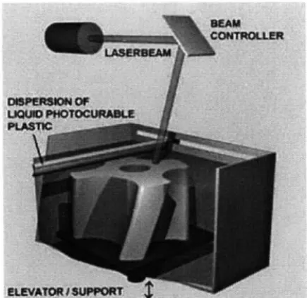
During the stereolithography (SL) process, a laser draws a layer of the desired object on the top surface of a photosensitive liquid resin, curing the top surface (fig. 16). Following each writing of a layer, the support surface holding the solidified resin moves down one layer's thickness at a time, recoating the top surface with liquid resin and the next layer is written on the top surface again. A light matrix of material must also be "drawn" under protruding parts of the objects in order to support them during the printing. In the end, the models are made out of a very durable, transparent resin. 3D Systems' stereolithography was the first RP process to be commercialized, starting in 1988 (fig. 17).1*
Fused deposition modeling (FDM) has been commercialized since 1991 (fig. 18). This processes 'draws' one layer of the desired object at a time with molten plastic. When a layer is complete the bed moves down and the next layer is drawn upon the previous one. Support material is drawn where needed throughout the process, as in stereolithography. The final models are made of a fairly strong ABS plastic. The MIT Department of Architecture currently owns a Stratasys FDM 2000, however the newest FDM machine on the market today is the Dimension 3D printer.
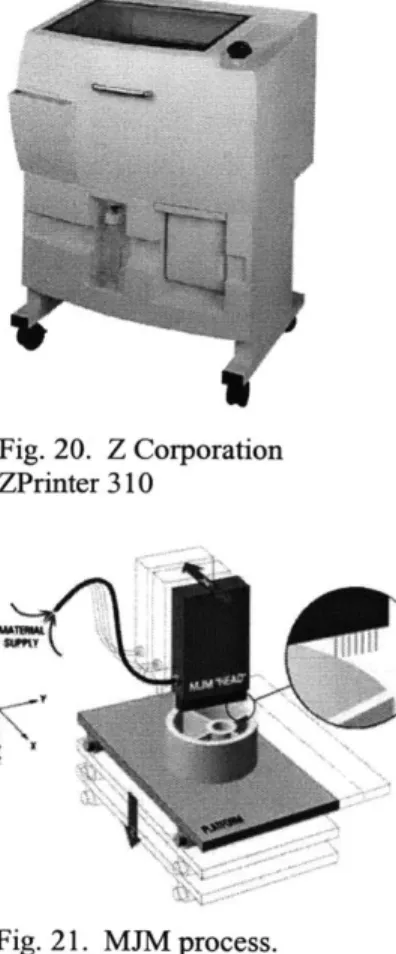
Commercialized in the late 1990s, three-dimensional printing (3DP) is rapidly working its way into the architectural design process more so than any other RP method (fig. 19). The architecture department at MIT owns the Z Corporation Z400 3D
Paul F. Jacobs, Rapid Prototyping & Manufacturing: Fundamentals of StereoLithography (Dearborn: Society of Manufacturing Engineers,
Fig. 20. Z Corporation ZPrinter 310
-9',I
t ~
Fig. 21. MJM process.
Fig. 22. LOM process.
Fig. 23. Hagia Sophia model fabricated by selective laser snterng.
printer along with a depowdering station and wax oven. Since MIT purchased the Z400, Z Corporation has released a more compact 3D printer, the ZPrinter 310, that can also print color (fig. 20). An inkjet-like printing head prints an entire layer of a given object with a water-based binding fluid on the top surface of a bed of fine, starch- or plaster-based powder. When the first layer of printing is done, the bed moves down, a thin layer of the powder is spread over the freshly printed layer, and the printing head repeats the process until the object is complete. The non-printed powder in the bed acts as the support material for the print. In the end, the models are made out of a brittle, plaster-like material. Finishing requires blowing off excess powder and lightly curing the outside surface with some sort of binding fluid or hot wax.
Also similar to an inkjet printing, multiJet modeling (MJM) prints with a head releasing tiny drops of melted, opaque wax to create the print. Each time a layer is completed the bed moves down and the next layer is printed until the object is complete (fig. 21). MJM is found occasionally in architecture schools and was introduced to the market in 1999. MJM machines include 3D Systems In Vision 3D Printer and Thermojet Printer.
The laminated object modeling (LOM) process creates objects by repeatedly laminating thin sheets of paper, plastic, or composites. Each layer has a profile cut into it by a laser or blade, and is laminated to the previous layer. The remaining material is used as support material (fig. 22). LOM has been commercialized since 1991 and currently appears to be the least utilized process compared to the SL, FDM, 3DP, and MJM processes.
Many variations of these technologies and other RP processes exist, but are not used in architectural model making mainly due to high costs. Some of these other processes are laser sintering, laser generation, and selective inhibition of sintering (fig. 23). The
prices of rapid prototyping machines currently run between $20,000 and $900,000.
CHAPTER 3:
SURVEYING THE ARCHITECTURAL DESIGN
FIELD
Chapter 2 presented the spectrum of tools available for use in the making of architectural models. This chapter focuses on a series of interviews I held with architects, professors, and students through which I learned about their differing views and uses of digital fabrication machines in their design processes. I surveyed a range of people in each of the three categories. Some people had used these machines very little while others had extensive experience. I found people that had more skeptical views about digital fabrication than others, and each person I spoke with provided me with a different perspective on these machines.
3.1 Primary Issues Unveiled
Eight primary issues arose through this survey which were very enlightening. I learned that the design process found in schools differs from the process found in offices. It appears that there are a couple of machines that are favored over other machines by the majority of the field. One fabrication process affects designs more than the rest, while others are less useful than some would hope. A particular group of machines can mislead designers about manufacturing methods, whereas another produces challenges to the academic community. Most of the people interviewed appeared to be very sensitive to the amount of time, money, and effort it takes to make a model. And finally, I found through a few of the interviews that physical models of architectural designs have more significance to them than just physically representing a building. The eight issues are discussed in
detail in the following sections.
3.1.1 Differing Design Processes
Architecture students and professionals have different objectives in their design processes and this leads to some frustration among the two groups. Students are very interested in learning the latest software and
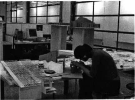
Fig. 24. Student making model in studio. (Naveem Mowlah)
Fig. 25. 3D printed models at Morphosis.
rapid prototyping technologies while they have the luxury of having access to these things at little or no cost. Because of this circumstance, architectural students learn to integrate these technologies into their design processes. Students also go through extensive design explorations when developing a studio project, employing most of the types of representation along the way (fig. 24). The students are taught that extensive exploration, is the way the design process works.
Professionals, on the other hand, have to make money. Of course, most architects would love to explore design options as extensively as they did in school, but few are able to afford that luxury. Another money-driven issue is that they cannot afford to try new technologies as freely as students since it is considerably more expensive to do so outside of an academic setting. Trying new software programs is costly not just because of the price of the program, but the time it takes to learn it and incorporate it into the office's design process. RP, discussed later, is still very expensive for architects to use relative to more conventional methods of model making.
A few rare firms exist, such as Morphosis in Santa Monica, California, that own their own laser cutter and/or 3D printer (fig. 25). Architects at Morphosis design their projects primarily in the computer through the use of 3D digital models. The 3D printer is a natural extension of such a process and they find it is cheaper than outsourcing 3D printing to outside parties. Since Morphosis' way of working is much closer to the academic design process in terms of design exploration and new technologies, a huge number of students want to work there. This causes frustration among students when there are too few firms that match what they are looking for in a job and they can't get it because everyone else is applying for the same position. This situation can also cause frustration for firms that utilize more conventional technologies when they hire freshly graduated designers with skills that are different than what the office needs.
Fig. 26. HP Designjet 430
3.1.2 Cost Issues and Evolving Technologies
Discussed earlier is the drastic difference between the student's cost for 3DP at school versus the professional's cost to outsource 3DP. In order to understand more about the cost issues that surround these new technologies, I thought it would be useful to compare the prices of the machines to the prices of large-format color plotters (something most schools and offices own). Hewlett Packard offers a whole line of large-format color plotters with a price range starting at $1,195 for the HP Designjet 430 24" wide format and ending with the HP Designjet 5500 60" wide format at $19,995 (fig. 26).
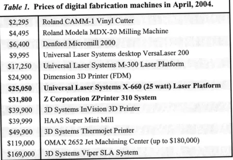
Below are the prices of all the digital fabrication machines mentioned so far, plus a few others that are useful for the architecture community (Table 1). One should keep in mind that the most expensive color plotter is $19,995, and even that is considered to be too expensive for many smaller firms.
Table 1. Prices of digital fabrication machines in April, 2004. $2,295 Roland CAMM-1 Vinyl Cutter
$4,495 Roland Modela MDX-20 Milling Machine $6,400 Denford Micromill 2000
$9,995 Universal Laser Systems desktop VersaLaser 200 $17,250 Universal Laser Systems M-300 Laser Platform $24,900 Dimension 3D Printer (FDM)
$25,050 Universal Laser Systems X-660 (25 watt) Laser Platform $31,800 Z Corporation ZPrinter 310 System
$39,900 3D Systems InVision 3D Printer $39,999 HAAS Super Mini Mill
$49,900 3D Systems Thermojet Printer
$119,000 OMAX 2652 Jet Machining Center (up to $180,000) $169,000 3D Systems Viper SLA System
The two most popular machines (shown in bold above) among the architectural community both exceed the price of the most expensive large-format color plotter. This is a part of the reason why most architecture firms outsource rather than purchase their own machines. In addition to the initial cost, most of these machines require annual
Fig. 28. Palladio STL model by Larry Sass.
maintenance, which can also be quite costly. Another factor is the continually evolving technologies which are costly and time-consuming. The laser cutter and 3D printer, as well as the 3D Systems Thermojet Printer (an MJM machine), are found in architecture schools frequently where there is more budgetary room for exploring new technologies.
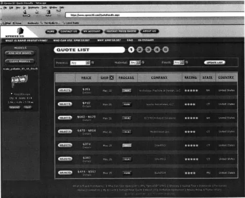
Companies such as Xpress3D provide outsourcing of RP and CNC processes through the internet (fig. 27). In order to learn how much companies such as Xpress3D charge, I submitted an STL file a model (fig. 28). The Palladio model's dimensions are 2.94"x4.84"x7.78" and the prices ranged from $281 for a 3DP to $814 for an SLA print. Since RP technologies change frequently and the machines are expensive and difficult to maintain, it makes sense for architecture offices to outsource rather than own their own machine.
Fig. 27. Xpress3D online RP quotes.
3.1.3 Favored Machines
Among professionals and students, the laser cutter and 3D printer proved to be the most favored digital fabrication machines. Each
Fig. 29. 3D print of typical architectural model by Service Point.
group responded differently, however. Professionals utilize the laser cutter more so than any other machine in the digital fabrication group. The 3D printer appeared to be the second most used, although it is still not well integrated into the design process by most architects. Meanwhile, students responded overwhelmingly that the 3D printer was their machine of choice, with the laser cutter coming in as a close second.
There are a few reasons why I think these machines were chosen as the favorites and why professionals and students view them differently. The reason 3D printing is used more by students than professionals starts with cost, as mentioned previously. MIT Architecture students only pay $3.50 per cubic inch of material, which adds up to $10-$70 for a completed 3D print. The key factor influencing the low price is that students are not being charged for the printing time and post-processing. Except for a rare handful, all professionals must outsource 3D printing, which can be expensive. Service Point, a reproductions company in Boston, Massachusetts, offers 3D printing as one of their services (fig. 29). Service Point includes the printing time and post-processing (dusting and sealing the model) in their fees, which ultimately forces the prices up to $300-$1,000 per print.
Another explanation as to why 3D printing is more popular in schools than in businesses is that students tend to three-dimensionally design within the computer more than professionals. Most architecture offices mainly work in 2D in the computer, sometimes incorporating a partial 3D model used to render specific views of the project." The 3D printer must have a complete 3D digital model to work from or no print can be made. Altering the design process to accommodate 3D printing needs can cost companies even more time and money. Architects would need to teach their designers a new design process, which is not a small task.
Fig. 30. Students building a model with laser cut parts; laser cutter in the background. (Christine Gaspar and Marlene Kuhn)
Service Point has noticed that there is a high level of interest in the 3D printing service they provide, yet very few architects are actually taking advantage of the service. Service Point's original target audience was architects, but when they experienced this hesitation they started targeting industrial designers as well, which has helped bring in more business. At the moment, Service Point makes about two to three prints each month, only one of which is usually ordered by an architect.
Jim Maitland, Service Point's manager of 3D operations, stated that a part of the problem is that most architects are simply not working with 3D digital models yet, which means they cannot take advantage of his 3D printing service.
Joshua Katz, in Washington, DC, provides many architectural design services, including 2D drafting, 3D modeling, conventional model building, and 3D printing. Since Joshua has included 3D modeling as one of his services, he has been much more successful with his 3D printing service than Service Point. Architects can give him whatever they have, whether it's a partial 3D digital model or even a set of 2D drawings, and he will create the 3D digital file needed to make a print. By providing this extra service and complete model finishing, including sanding and painting, he produces up to ten prints per week.
The laser cutter has become a standard part of the academic studio (fig. 30). It has proven to be a faster, more precise method of making cuts one would otherwise make by hand. Unlike the 3D printer, the laser cutter has been demystified, helping it remain the better utilized of the two in spite of the popularity of the 3D printer. Some of this is attributed to the cost of 3D printing, while the rest could be blamed on its inestimable qualities.
3.1.4 Most Influential Machine
Although the 3D printer (fig. 31) is not as well utilized as the laser cutter, it is currently having the greatest impact on the design process in schools. Students are the primary users of this fabrication method,
Fig. 31. Z Corporation ZPrinter 310
Fig. 32. 3D printed physical representation of digital model. (Nicolas Rader)
Fig. 33. 3D prints of Palladio building by Larry Sass presenting different scales derived from the same digital file.
which explains why changes would happen here first. Closely involved in the academic studio, professors have been witnessing the changes that have occurred in students' design processes as these new technologies become available. The laser cutter has not had as much of an impact on the design process because its capabilities directly correspond to the designer's handmade model making methods. The 3D printer, however, requires an entirely different method of working due to how the digital file must be set up and how the object is produced.
The effects on the design process are both positive and negative. Through my survey, I found four positive and three negative effects on the design process when designers use 3D printing as one of their methods for model making.
Positive effects of using 3D printing are:
1. Designers are physically exploring different designs than they would otherwise be able to with a physical model (fig. 32). If the 3D printer was not available, the designs would remain in the computer as digital models or be physically represented in a much more rough, imprecise manner.
2. Designers are now using this technology to confirm the quality of their digital models. 3D printing provides an honest representation of a digital model, revealing detrimental imperfections that would otherwise go unnoticed.
3. Designers are exploring more designs in a shorter amount of time. Although not quantified, a few regular users of 3D printing noted this as one of the reasons they prefer using the technology as one of their primary methods of creating physical models.
4. Designers are evaluating their designs in a range of scales from a single model (fig. 33). Since 3D printing requires the designer to create a 3D digital model, that single model can be
Fig. 34. Anonymous student model of auditorium.
printed at a variety of scales, ranging from details to urban sites.
Negative effects of using 3D printing are:
1. Designers are designing for the 3D printer rather than for construction processes used to construct buildings. Therefore, designers are creating buildings with more surfaces and less slender elements (Fig. 34). 3D prints are made of a brittle, plaster-based material that tends to break very easily. Designers who use this machine to create physical representations of their designs tend to design for the machine's output, which ultimately forces them to shy away
from slender elements.
2. Students are further removed from the building process. A concern to many professors and professionals is that students become somewhat removed from the building process of architecture when they use the 3D printer as a model building technique. The machine creates the physical object, not the designer.
3. Students are designing homogeneous buildings. The danger here is that students begin to see buildings as monolithic objects and not as an assembly of a wide variety of components. Buildings consist of many different types of materials assembled together in many different ways, yet a 3D print consists of one material printed in a monolithic fashion.
3.1.5 Misleading Fabrication Processes
The 3D printer is not the only rapid prototyping method to provide inaccurate representation of real construction processes. 3DP, FDM, SL, MJM and LOM all manufacture parts through a homogeneous, additive, layer-by-layer process, which is far removed from any real construction process. Concrete or rammed earth construction are close, but elements such as windows, reinforcing bars, and plumbing must still be placed in the walls during the construction process.
3.1.6 CNC Milling Challenges
CNC milling machines are becoming more common around architecture schools, yet are appearing to be less useful than some would hope. Many of these machines are desktop milling machines, such as the Modela or Denford that MIT owns; however, a few schools have acquired large-scale machines similar to the HAAS described earlier.
Before conducting my interviews and experiments, I thought the milling machine would undoubtedly be a great resource to have in any architecture school. However, I realized after interviewing students who have had hands-on experience with these machines, that their experiences are not meeting the expectations of the professors who introduced the machines to the school. Only when this knowledge is coupled with class lectures and tours, can these machines become a
significant teaching tool. Even so, a few students commented that using the machines did not help them at all and that it was solely what they learned in class and on tours of offices and shops that helped them
grasp manufacturing concepts.
3.1.7 Importance of User-Friendliness
Architects and students are very sensitive to the amount of time and money it takes to represent a design. The other major factor is user-friendliness. If a fabrication method is too tedious to learn and use, people will find another method that is more straightforward. I think
this is another reason why the vinyl cutter, FDM, and especially the milling machines are not exploited like the laser cutter and 3D printer.
Sending prints to the 3D printer is analogous to sending a print to a standard laserjet printer. The reason architects can look past the tedious post-processing is that the overall concept of 3D printing is simple to grasp.
Operating the laser cutter is analogous to the slightly more complex process of large-format, color printing. Fortunately, this is something most architects are familiar with, which is why laser cutting appears user-friendly. Plotting from AutoCAD is a standard part of the architectural design process for most architectural designers, and that is exactly how they send files to the laser cutter. Making changes to the file is also comfortable because it is simply altering 2D drawings in AutoCAD.
3.1.8 Significance of Physical Representation
The physical representation of a digital file has a significance of its own for two reasons. One reason has to do with the spirit and sensibility of the design it is representing. The other has to do with the reality it brings to the 3D digital model.
Physical models do not just represent the reality of an architectural design, but capture the spirit and sensibility of the design as well. Some people prefer handmade models over laser cut ones because the laser cut models tend to feel sterile. 3D prints of architectural projects run the risk of losing the sensibility of the design, yet they can sometimes introduce a new kind of spirit as well. 3D printed models typically emerge as homogeneous, precise, unfinished models that tend to have little or no spirit, such as a 3D print of a typical house. However, some objects that are fabricated with the 3D printer cannot be fabricated in any other way, and these models tend to have a liberating spirit to them because they bring the digital to life.
Another significant aspect of physical representation is the reality the physical model brings to the digital model. One could argue that physically representing a digital design is necessary for the architectural design process. During one of my interviews, a comparison was made between the architectural design process and the graphic designer's design process. When designing a book cover, a graphic artist starts by creating the image in the computer, visually interacting with it through a screen. In order to evaluate the image accurately, the artist must repeatedly print the design out on paper and adjust it in the computer. The computer image is not a reliable representation of the final design."
This seems synonymous to an architect designing a building in the computer, repeatedly stopping to create 3D prints of the building in order to evaluate how the 3D space actually works. The designer knows what adjustments are needed on the digital model by physically experiencing the design, both spatially and contextually. One main difference I see between the graphic design process and the architectural process is the homogeneous character of 3D prints. Materials in architecture are the same as colors to the graphic designer. Today's 3D prints do not allow architects to evaluate how materials will interact in their designs. Maybe this is where developments in 3D printing can help in the future.
Fig. 35. FDM tolerance testing.
Fig. 36. FDM components of one-way arch.
Fig. 37. Tolerancing of FDM parts.
Fig. 38. FDM one-way arch.
CHAPTER 4:
EXPERIMENTING WITH DIGITAL
FABRICATION
I am in the fortunate position of having access to eight digital fabrication machines and took advantage of the opportunity. I conducted three experiments on these machines in order to gain a better understanding of each process. In all of my explorations I utilized one or more of the machines to which I have access in the MIT Department of Architecture and at the Center for Bits and Atoms Fab Lab.
4.1 Experiment 1:
Fused Deposition Modeling of Self-Assembled Domes
The only machine used for this experiment was the Stratasys FDM 2000 which prints objects with a robust, white ABS plastic. I worked on this project with Larry Sass and Sarah Hudson for the Center for Bits and Atoms during the summer of 2003. (In this section, whenever I say "we" I am referring to Larry, Sarah, and me.) The ultimate goal of this project was to digitally fabricate complicated dome structures based on designs developed in eifForm, a performance-based computer program, developed by Kristina Shea, that generates structural forms.13
We started studying the machine by documenting tolerances, material usage, and print times (fig. 35). We learned that one needed to design for the FDM process in order to create the parts we were intending to print. Once we felt we understood the Stratasys, we began designing and building simple, self-assembling arches and domes. In this case, "self-assembling" refers to a structure whose components dictate the order in which they should be assembled (fig. 36). The first few assemblies were self-supporting, one-way arches consisting of many interlocking parts that dictated the method with which they must be assembled. Before moving on to the next step, we went through the
"3 Shea, Kristina. "Digital canopy: high-end computation/low-tech construction" arq, 6.2 (2002) 230-245
Fig. 39. FDM two-way arch.
tedious process of tolerancing the interlocking parts so they would fit together tightly (fig. 37).
The one-way arches (fig. 38) were followed by two-way arches, which forced us to start thinking of more unique parts (fig. 39). The two-way arches were followed by an elaborate half-dome made of many repetitious, interlocking components, some of which were unique (fig. 40). The regular half-dome was followed by an irregular half-dome (fig. 41). We explored two different types of connections on the irregular dome, one of which was chosen as the connection for the next project. We worked toward the conclusion of a very complicated partial-dome assembly consisting of many unique components where there was only one way to assemble them (fig. 42).
Fig. 40. Regular half-dome.
Fig. 42. FDM irregular partial dome.
Fig. 43. FDM offline.
Fig. 41. Irregular half-dome digital file showing parts arranged for FDM.
We learned to like the FDM process because the ABS printed parts were robust. Once we figured out the tolerancing, we were able to design parts that friction-fit together, which was very helpful in creating self-supporting assemblies. Learning how to operate the machine was not too difficult; however, it was tedious enough that Sarah and I had to be assisted for the first few times we sent prints to it. Occasionally the machine would encounter errors, which we had to learn to fix (fig. 43).
Through this experiment, I realized that in order to make the FDM parts work together the way I intended them to work, I had to design for the machine. I had to have a decent understanding of the tolerances the machine worked within, how the output would appear if the objects were oriented in different positions, and where the support material
would be located. If I didn't keep these things in mind as a I prepared the parts to be manufactured, I would have difficulties getting the parts to work the way I intended.
Fig. 44. FDM typical joint.
Fig. 45. FDM typical joint with laser cut plexiglass.
Fig. 46. Triangulated surfaces of irregular dome, cut with CNC vinyl cutter.
Fig. 47. Selected section of dome. Structure modeled with FDM and surfaces cut on CNC vinyl cutter.
4.2 Experiment 2:
Digital Fabrication of Self-Assembled Joints
After the first experiment, Sarah, Larry, and I continued to work on the complicated partial-dome assembly utilizing four digital fabrication machines. (I will refer to the three of us as "we" again in this chapter.) We continued to use the FDM, in addition to using the CAMM-1 vinyl cutter, the laser cutter, and the Roland MDX-20 milling machine. We worked in a general-to-specific manner, starting with the overall dome design and worked toward detailing the joints. We originally intended to complete the experiment by milling the components out of aluminum; however, the more we learned about the manufacturing process, the more we realized that our design was not very conducive
for milling.
We started by creating a monolithic representation of a typical joint on the FDM (fig. 44), followed by another typical joint fabricated piece-by-piece on the FDM (fig. 45). Then we moved to cutting all of the dome's tessellated faces out of acetate on the Modela CAMM-1 desktop vinyl cutter. Sarah created a cut sheet of each triangular face and "printed" it on the CAMM-1. Once all of the faces were cut, she taped them together to create a small physical representation of the structure (fig. 46).
Then we chose which joints of the triangulated structure we were going to model and cut those panels on the CAMM-1 as well. The thin acetate panels were taped together as before and overlaid on an abstract FDM model of the triangulated structure (fig. 47). The seams of the two models, fabricated by different machines, lined up with each other perfectly. This verified that we were able to convey information accurately to multiple machines.
We chose one of the joints to design in detail and used the FDM and laser cutter to create a prototype (fig. 48). The fused deposition modeled joint and struts fit together well with the laser cut panels. The
Fig. 48. Disassembled FDM parts and laser cut panels.
Fig. 49. Rigid foam assembly milled on the Modela MDX-20 with laser cut panels.
Fig. 50. Milled rigid foam parts, milled on the Modela.
next test was to mill the components in rigid foam on the Modela and, if that went well, ultimately mill out of aluminum on the HAAS.
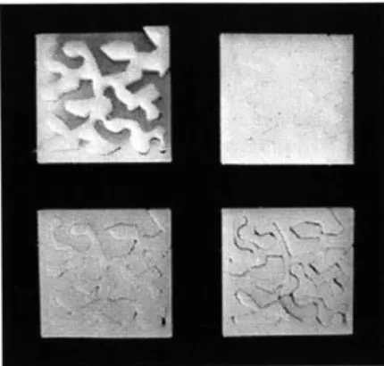
Milling on the Modela was generally a good experience (fig. 49). I milled the three-joint structure out of rigid foam which ended up being twenty-three parts in all (fig. 50). The assembly called for nine glass panels which I laser cut out of acrylic. Ultimately, the entire assembly took weeks to manufacture. Milling those twenty-three parts taught me that we had not designed the parts very well for milling, even though when we started we thought we had designed the parts well. The assembly still went together well, but comparing the physical output to the digital model revealed areas that could have been better designed.
When we saw that the components we had designed did not work as well as we had hoped, we decided to redesign them before proceeding to mill them out of aluminum. After a few days of digitally modeling these complicated joints, we came to the conclusion that it was not practical to manufacture this joint by milling. Casting turned out to be the most appropriate manufacturing method for such a joint, and since we wanted to stay focused on digital fabrication, we decided to end this experiment with the milled foam assembly.
What we leamed was that there are appropriate and inappropriate methods of manufacturing for different parts. When we tried to mill parts that were not meant to be milled, they come out looking worse than desired, they take a long time, and in the end, they did not work properly. A designer must fully understand what the fabrication process will be when he or she designs a building or component for a building in order to design for that process in the digital model. Otherwise, the designer and fabricator will both be very frustrated.