Controlling a team of robots with a single input
The MIT Faculty has made this article openly available.
Please share
how this access benefits you. Your story matters.
Citation
Ayanian, Nora, Andrew Spielberg, Matthew Arbesfeld, et al.
"Controlling a team of robots with a single input." In 2014 IEEE
International Conference on Robotics and Automation (ICRA), 31
May-7 June 2014, Hong Kong, China. © 2014 IEEE.
As Published
https://dx.doi.org/10.1109/ICRA.2014.6907088
Publisher
Institute of Electrical and Electronics Engineers (IEEE)
Version
Author's final manuscript
Citable link
https://hdl.handle.net/1721.1/129348
Terms of Use
Creative Commons Attribution-Noncommercial-Share Alike
Controlling a Team of Robots with a Single Input
Nora Ayanian
Andrew Spielberg
Matthew Arbesfeld
Jason Strauss
Daniela Rus
Abstract— We present a novel end-to-end solution for dis-tributed multirobot coordination that translates multitouch gestures into low-level control inputs for teams of robots. Highlighting the need for a holistic solution to the problem of scalable human control of multirobot teams, we present a novel control algorithm with provable guarantees on the robots’ motion that lends itself well to input from modern tablet and smartphone interfaces. Concretely, we develop an iOS application in which the user is presented with a team of robots and a bounding box (prism). The user carefully translates and scales the prism in a virtual environment; these prism coordinates are wirelessly transferred to our server and then received as input to distributed onboard robot controllers. We develop a novel distributed multirobot control policy which provides guarantees on convergence to a goal with distance bounded linearly in the number of robots, and avoids inter-robot collisions. This approach allows the human user to solve the cognitive tasks such as path planning, while leaving precise motion to the robots. Our system was tested in simulation and experiments, demonstrating its utility and effectiveness.
I. INTRODUCTION
Multirobot applications have been extensively explored in the literature, including monitoring [1], [2], manufacturing [3]–[5], and manipulation [6], [7]. Yet while these (and many other) applications have a potential impact well beyond the laboratory, most of the results can only be used by experts with programming and robotics experience, limiting their reach. Systems that can be used with graphical (or other) user interfaces are key to bridging the gap between researchers in the lab and the outside world. Most state of the art controllers allow a single user to provide input to only a single robot at a time. This does not scale and we seek to enable a single user to control many robots simultaneously with a single input.
Developing an end-to-end real-time solution for multirobot systems present numerous challenges. Two significant chal-lenges are in designing an effective interface that allows a user to specify how to use the team of robots, and developing distributed coordination algorithms which guarantee that tasks will be completed. Both of these present significant challenges on their own, but developing a solution for both simultaneously is an extremely challenging task.
Developing a user interface for robots presents a valuable opportunity to bring the human in the loop. Humans and robots have many complementary strengths: while humans excel at high-level cognitive tasks, robots triumph when
This work was completed at the Computer Science and Artificial Intelligence Laboratory (CSAIL), MIT, Cambridge, MA 02139, USA. N. Ayanian is currently with the Computer Science Department at USC, Los Angeles, CA, USA. J. Strauss is currently with Palantir.
{nayanian, aespielberg, arbesfeld, jstrauss,
rus}@csail.mit.edu. Supported by ONR MURI ANTIDOTE
N00014-09-1-1031, SMARTS N00014-09-1051, and The Boeing Company.
it comes to repetitive, computational ones. This notion of human-robot task delegation has inspired a significant amount of literature. In general, however, this literature does not address control, focusing instead on human-robot inter-faces, such as determining useful tasks and how they might be specified [8], developing natural or intuitive gestures [9], creating image-based interfaces for nonexperts [10], evaluat-ing the efficacy of interface technologies [11], or examinevaluat-ing application-specific interaction issues [12].
In the multirobot domain, McCann et al. present a method by which multiple users can direct a team of robots [13], but this work does not address control and also only presents simulation results. Podevijn et al. present a method for controlling subgroups of swarms using arm gestures and a Microsoft Kinect [14]. However, since their swarm con-trollers do not guarantee convergence in environments with obstacles, long command sequences may result in order to guide stuck robots to their goals. Those works that do address control are typically for a single robot, such as using multitouch gestures to control an articulated robot [15].
There have been many works on synthesis of multirobot control policies from high-level specifications, e.g. using linear temporal logic [16] or structured english [17], but writing these specifications still requires a good deal of skill. The contributions of this work are an end-to-end solu-tion for navigating teams of robots from one locasolu-tion to another in complex environments. We present a solution that addresses distributed multirobot control in a way that enables the development of a simplified user-interface. We also present and demonstrate an example interface for the system. Our system relies on a human-in-the-loop making critical decisions about a multirobot team navigating an environment on a tablet-based multitouch display (using the Apple iPad). The iPad displays a virtual environment with four views (three orthographic and one isometric projection) and real-time robot positions for visual feedback (Fig. 1). The robots are enclosed by a bounding box (prism) which the user can translate and scale using multitouch gestures, maneuvering it to the desired location and avoiding obstacles. This gives the user the capability to decide which risks are worth taking, and how close to get to certain hazards. As the prism is manipulated, its coordinates are regularly recorded. The union of a subset of these recorded prisms defines the free space for the robots to navigate to their destination. Figure 2 provides a pictorial view of our control loop.
The benefits of this type user input are many. In applica-tions when there are multiple risk factors involved it may be difficult to develop a proper navigation heuristic and a human may be able to make a quick and appropriate decision.
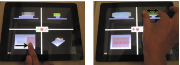
Addi-Fig. 1: The iPad App interface: four views, with manipulation options at center. (Left) Touch and drag to translate the prism. (right) Zoom in or out to scale the prism.
Fig. 2: A sample (asynchronous) control loop. Commands are sent from the input device to the server, which sends prism vertices to the onboard controllers of the robots which synthesize commands. Robots broadcast their positions to the server, which relays them to the input device to be rendered (not pictured is communication between robots within range).
tionally, some environments are extremely difficult to model. In many cases, the environment model must be compatible with a controller–for example, polytope-based controllers require environments defined using polytopes, which may be time-consuming or complex to build while maintaining completeness. Abstracting the robots’ environment to a union of rectangular prisms reduces its complexity and makes it easier for a user to choose safer paths in real time.
The outline of this paper is as follows. In Section II and III we define the problem and preliminary definitions, respectively. Section IV presents our solution, with analy-sis in Section V. Software implementation is discussed in Section VI. We present simulation and experiment results in Section VII and conclude with a discussion in Section VIII.
II. PROBLEMSTATEMENT
Consider a team of n homogeneous robots VR= {ri|i =
1, . . . , n} that must navigate to a destination set D in a shared, constrained, bounded environment. Each robot has the configuration xi ∈ Rd, d ∈ {2, 3} representing its
position in Cartesian space, with dynamics:
˙xi= ui, xi∈ Xi⊂ Rd, i = 1, . . . , n. (1)
In order to maintain safety, robots must maintain a minimum distance from each other, λmin> 0.
Problem 2.1: Consider a team of homogeneous robots VR
with dynamics (1). For some initial state x0 and destination
D, find a control policy which will drive the robots to within a bounded ball of D while avoiding collisions with the environment and maintaining a distance greater than λmin
between robots.
III. PRELIMINARIES
We seek a solution to Problem 2.1 that can be synthesized automatically from high-level specifications. The controller must be usable by non-experts who may not have experience with code or robots. To that end, we have developed a solution that generates low-level controllers for individual robots from simple multitouch inputs on an iOS interface.
In this work, we assume
• a user is capable of navigating a rectangular prism via multitouch input in a constrained environment such that the final position of the prism encloses the set D without colliding with the environment;
• all agents are identical;
• the environment is static;
• robots initiate with at least λmindistance between every
pair of robots;
• each robot is capable of self-localizing;
• robots are capable of transmitting only their current pose
to other robots within a radius δ > λmin;
• robots are capable of globally receiving limited infor-mation from a server about the environment;
• the initial and goal points in the environment must be connected.
Note we make no assumption about the goal set other than being reachable, and that it can be enclosed by a final prism. The controller is implemented in two parts: an iOS inter-face to receive and parse user input and display the current system state, and a Python-based server which receives user commands and interfaces with the robots via ROS [18]. A. Abstracting the Environment
The environment of the robots is determined by user inputs on the iOS interface. The interface shows real-time position of the robots in the environment, and an initial bounding box for the robots P0. In 3-D, the robots’ bounding
box is a rectangular prism; in 2-D, it is a rectangle. We assume obstacles do not exist within this initialized prism. We choose a rectangular prism since it is simply described by 2d halfspaces, and intersections are easy to compute. Other shapes can also be chosen, with changes to the virtual forces (Sec. IV). We henceforth refer to the rectangle or rectangular prism simply as a prism.
The user manipulates the prism on the screen (Fig. 1), dragging and scaling, so it navigates the space without contacting obstacles in the environment (while this requires the user to avoid obstacles, a physics engine could be used to detect and prevent collisions). Since the robot state is defined as a single point and does not capture the robot’s physical extent, on the interface the environment must be padded by the robots’ size to ensure robots do not collide with obstacles. As the user manipulates the prism enclosing the robots on the screen, new coordinates are transmitted to a server,
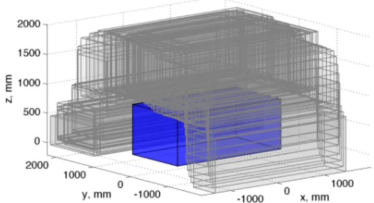
Fig. 3: The free space generated by multitouch inputs on the iOS app is the union of the prisms shown in grey. An obstacle is shown in blue.
where the union of a subset of those prisms is used as an abstraction of the environment. A detailed description of the iOS application is presented in Section VI-A. This abstraction of the environment defines the free space of the robots. In the current work, prisms must be axis orthogonal (i.e. prism rotations are not allowed).
Definition 3.1: The free space of the robots is the finite union of rectangular prisms F = SP
j=1Pj, which are a
subset of the prisms generated by the multitouch interface that satisfy µ(PjT Pj+1) ≥ 0.5µ(Pj), where µ(·) is the
Lebesgue measure of the set.
Figure 3 shows the free space of the robots generated from the iOS app in the experiment in Section VII-B.
Within each prism, a robot activates a different on-board controller which forces the robot to the centroid of the prism. Once within the next prism, the robot activates the controller for that prism, sequentially composing controllers until reaching the goal. For each robot, we call the prism in which it is located and for which control is active the current prism. The current prism is determined as the prism with the highest index in which the robot is located. This means that robots can skip over some prisms in the sequence, which is key to our proof of convergence. It is important to note that at any time step, the current prism across the team of robots need not be the same. In other words, the robots progress through the sequence at an individual pace.
IV. CONTROLLERSYNTHESIS
The abstraction of the environment enables the use of a simplified control policy, while still providing guarantees of safety and convergence. Key to our approach is that a prism Pj ∈ F must overlap the previous one Pj−1by at least 50%
of the volume (for d = 3) or area (for d = 2) of the previous prism Pj−1. This guarantees that the centroid of the current
prism is inside the next prism in the sequence.
We use a “virtual force” to drive each robot to the centroid of its current prism. In the case of a single robot, once the robot has reached the current prism’s centroid it is inside the next prism in the sequence, and can switch to that prism’s virtual forces. Robots cannot move backwards
0 5 10 15 20 25 30 0 200 400 600 800 1000
Distance from boundary, mm
Magnitude of force β = 0.1 β = 0.2 β = 0.3 β = 0.4 β = 0.5 β = 0.6 β = 0.7
Fig. 4: Change in force vs distance from a boundary from varying β for fixed length of influence (1000mm), α = 1000.
in the sequence of prisms; the index of the next prism must be higher than that of the current prism. The case of multiple robots requires additional inter-robot forces to prevent collisions between robots.
Intuitively, we would like robots to be strongly repelled from the prism boundaries and into the safer, inner part of the prism, where they are eased toward the center. Specifically, at the prism boundary, infinite force must repel the robot, and the force must disappear to zero at the center.
There are many functions which would satisfy these re-quirements, including the negative gradient of a navigation function [19]. However, we choose a function that allows more control over the magnitude of the force within the prism without requiring hand-tuned parameters for each prism. Since we desire similar properties of the prism forces and interrobot forces (the force must be infinite at the minimum distance, and zero at the maximum distance), we use a generalized force function for both types of forces:
f (d) = ∞ , d < 0 α/dβ− γ , d ≤ (α/γ)1/β 0 , otherwise (2)
Here, d is a distance, and the parameters α, β, γ allow a user to tailor the function to their application, modulating the rate of change of the force while forcing it to disappear to zero over the desired length of influence l = (α/γ)1/β. Figure 4
shows how the magnitude of f (d) changes as β is varied for fixed length of influence l = 1000mm, α = 1000, and γ = α/l1/β (to achieve f (d = 1000) = 0).
A. Prism Forces
Each prism can be described as the intersection of 2d halfspaces Pj = {q | Hjq ≤ Kj, q ∈ Rd} where Hj =
[Hj,1T Hj,2T · · · Hj,2dT]T, with each row ||Hj,k||2≡ 1.
The force on each robot ri from its current prism Pj is
the sum of the forces from each facet of the prism, ui,j= − 2d X k=1 fip(dpi,j,k)Hj,kT, (3) where : dpi,j,k= Kj,k− Hj,kxi
is the distance from robot rito the kthfacet of prism Pj, and
Fig. 5: The prism vector field on a 2D prism (blue) shown with the next prism in the sequence (red). A robot would be attracted to the center of the blue prism, and would transition to the red prism once inside it.
all prisms, facets, and robots. We vary γ between prisms and facets to fix the length of influence so that the force from each facet disappears to zero at the centroid (chose γ such that the length of influence is half the length of the respective side of the prism)1. Figure 5 shows the vector field on a 2D prism in blue, with the next prism in the sequence in red. B. Interrobot Forces
We use the same generalized force function to calculate interrobot forces. Let the distance between a pair of robots be dri,m= ||xm− xi||2. The minimum safe distance between
robots is dri,m > λmin, where the robots are strongly repelled
(with infinite force at λmin). As mentioned in Sec. III,
we assume that robots can transmit their current position to robots in a disk of radius δ. To prevent unnecessary interaction at long distances, we allow robots’ positions to influence other robots at a maximum distance of λmax≤ δ.
At λmax, the interrobot force disappears to zero.
Let the Vi⊆ VR be the set of robots within λmaxdistance
of robot ri. The interrobot force on ri is the sum
ui,R= 1 |Vi| X m∈Vi fir(dri,m− λmin) xi− xm dr i,m , (4)
where |Vi| is the cardinality of Vi, and fir(dri,m) ≡ f (dri,m)
with parameters α, β the same as for the prism forces, and γ ≡ γr, fixed across all robots such that (α/γr)1/β = λmax− λmin. We divide by the number of robots to prevent
interrobot forces from overcoming the prism force (we use this in Proposition 5.2). The input to each robot is the sum:
ui= ui,j+ ui,R. (5)
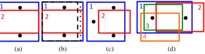
C. Overcoming local minima by randomized subdivision Systems which rely on combining multiple potential func-tions can be subject to local minima. For example, Fig. 6 shows three scenarios where a perfect alignment of robot and prisms can prevent the progress of the robots.
The scenarios presented in Fig. 6(a-c) correspond to sets of measure zero, and even a slight misalignment of the robots will cause forces that will destabilize these unstable minima2.
A simple distributed method can overcome these local minima. If a robot that is within the length of influence of another robot does not make progress toward the goal, and 1If prism overlap greater than 50% can be used to reduce jitter in discrete implementations. Choose γ so that forces reduce to zero before the centroid but within the smallest overlap region satisfying the overlap percentage.
2In implementation, noise practically eliminates this issue.
3" 1" 1" 2" 2" 1" 2" 3" 1" 1" 2" 2" 1" 2" 4" 1" 2" 1" 2" 1"2" 1"2" (a) 3" 1" 1" 2" 2" 1" 2" 3" 1" 1" 2" 2" 1" 2" 4" 1" 2" 1" 2" 1"2" 1"2" (b) 3" 1" 1" 2" 2" 1" 2" 3" 1" 1" 2" 2" 1" 2" 4" (c) 3" 1" 1" 2" 2" 1" 2" 3" 1" 1" 2" 2" 1" 2" 4" (d)
Fig. 6: Scenarios where summing potential functions causes local minima. (a), (c) The current prism (blue, 1) is the same for all robots, and perfect alignment prevents any robot from progressing to the next prism (red,2). (b) Subdividing the current prism can eliminate local minima. (d) The robot on the right prevents the robot on the left from progressing from 1 (blue) to 2 (red), and the left robot prevents the right robot from progressing from 2 to 3 (green). Since robots need not visit every prism, the left robot can transition directly to 4.
is not within (n − 1)λmax of the goal, it can initiate its own
subdividing sequence. Consider the robots in Fig. 6a. They can each independently subdivide prism 1 into a smaller subset, by choosing at random a facet to translate closer to itself by a random (but small) distance. For example, one robot might choose to reduce the facet to the right in Fig. 6b to the dashed line, while the other might choose to reduce that same facet to the dotted prism. Then, each robot would apply the control input (3) for their individual new prism, changing the centroid it is attracted to, and displacing the balance between the forces. This sequence can continue until the robots are no longer in a local minimum, when they either revert back to the original prisms or proceed to a future one.
V. ANALYSIS
In this section, we study the stability and convergence properties of the controller (5). We will show that all robots reach within (n − 1)λmax geodesic distance of the goal.
Within the proofs, we call a robot that is not within λmax
of any other robot a singleton. For a robot ri, any robot
within λmax belongs to its group (Note that a robot rm in
the group of rineed not have the same group as ri); we can
also say these robots are connected as in a graph. For a robot ri, any robot to which it is directly or indirectly connected is
in its extended group. We measure progress toward the goal as transitioning to a future prism in the free space sequence of prisms.
First we show that no robot can escape the free space or collide with other robots.
Proposition 5.1: Singletons cannot escape the free space. Proof: Assume WLOG that xi ∈ Pj and Pj is the
highest indexed prism for which this is true. There are two scenarios: (A) ri inside and (B) ri outside of the length of
influence of the kth facet of P
j.
(A) If ri is within the length of influence of the kthfacet,
the control input (3) due to this facet pushes the robot away from this facet. Also, the control input due to the opposite facet has no affect, since ri is outside of the length of
influence of the opposing facet. Therefore, ri will be driven
(B) If ri is outside of the length of influence of the kth
facet, the facet has no impact on the control input. The opposing facet pushes ri toward the kth facet, but this input
disappears to zero at exactly the interface between the lengths of influence of the two facets. Therefore riwill not be driven
any closer to the facet than the length of influence.
This is true for any facet k in any prism Pj, therefore a
singleton cannot escape the free space.
Proposition 5.2: Non-singletons cannot escape the free space or collide with other robots.
Proof: Assume that a robot has either (A) escaped the free space, or (B) gotten too close to another robot.
(A) If ri has escaped the free space, this means the
interrobot force has overcome the prism force of its last current prism Pj, forcing ri to exit through some facet of
the prism, facet k. Since the inward force due to the prism ui,jon ri is infinite at facet k, this means there exists some
infinite force to overcome ui,j. Since the interrobot forces are
averaged among ri’s group, the worst case is when a single
robot rmis pushing ridirectly into facet k with infinite force,
thus ||xm− xi||2≤ λmin. But since ri also imposes a force
on rm, rmmust move away from ri, thus the interrobot force
will decrease, and ri will move inward from the boundary.
Therefore, ri cannot escape the free space.
(B) If ri has gotten too close to another robot rm, this
means the sum of the forces from the other robots in the group of ri as well as the prism force have overcome the
force from rm. ri has gotten too close to rm when ||xi−
xm||2 ≤ λmin. Since we assume the robots initialize with
distances between them greater than λmin, this means that at
some time previous instant t, ||xi− xm||2> λmin. Thus, at
time t, the force imposed on ri from rm is finite. Assume
that the force driving ri toward rm due to other robots and
the prism is infinite. At some t0 > t ri has moved closer
to rm and further away from the other robots and the prism
boundary, such that the force from the other robots and the prism boundary is now finite. Since this force pushing ri
toward rm is finite, it cannot overcome the infinite force at
||xi− xm||2= λmin, therefore this cannot occur.
Since we have shown that robots cannot escape the free space and cannot come within λminof other robots, we now
show that all robots make progress toward the goal. Proposition 5.3: Singletons make progress toward D.
Proof: Assume WLOG that the singleton ri is in Pj
and the next prism in the free space sequence is Pj+1. Also
assume that xi∈ P/ j+1. ui,j drives xito the centroid of Pj.
Since Pj+1 overlaps at least 50% of Pj the centroid of Pj
is inside Pj+1, and the robot progresses to Pj+1. This is
true for any index i in the set P , therefore the singleton will always make progress toward the goal.
Now we show that in a group of robots, at least one makes progress, and by recursion, all make progress.
Proposition 5.4: In a group of non-singleton robots, at least one robot makes progress toward D.
Proof: In an extended group of non-singletons, where none of the robots are in the last prism, there are two cases. (A) If the robots are not stuck in a local minimum, at
least one robot is moving until (1) it proceeds to a future prism (since by construction robots cannot move backwards in the sequence), in which case one robot has made progress, or (2) eventually the group comes to equilibrium at a local minimum, in which case (B) applies.
(B) If the robots are stuck in a local minimum, the robots will initiate the random modification of their current prisms presented in Sec. IV-C. Since the adjusted facet and the adjustment size is chosen at random, eventually the robots will end up with unequal prisms. This will change the centroid that each robot is moving towards, disrupting the balance of forces. Eventually, due to the random nature of the modification, at least one robot will break out of the local minimum and progress to a future prism.
While Proposition 5.4 applies for a fixed group, if the group changes (by robots joining or exiting) we can apply the same results to the new group.
Corollary 5.5: All robots progress toward the last prism. Proof: Follows by recursion on Proposition 5.4. Theorem 5.6: Consider the system (1) in the space F , with control input (5). Every robot reaches within (n − 1)λmax geodesic distance of the centroid of the last prism.
Proof: Assume WLOG that r1has reached equilibrium
and is not within (n − 1)λmax geodesic distance of the last
prism. By Proposition 5.4, local minima cannot appear in a group where none of the robots are in the last prism. Therefore, at least one robot, which we call WLOG r2, in
the extended group of r1 is in the last prism. However, since
there are only n robots, and the maximum length between each pair of robots is λmax, the maximum geodesic distance
between r2and the robot farthest away must be (n−1)λmax.
This contradicts our assumption, and therefore r1 must be
within (n − 1)λmax geodesic distance of the last prism.
Theorem 5.7: The control policy (5) solves Problem 2.1. Proof:By Theorem 5.6, all robots reach within nλmax
geodesic distance of the last prism. By our assumptions in Sec. III, the goal D is within the last prism. Therefore the maximum distance between any robot and the goal D is the sum (n − 1)λmax + ||L||2, where L is the length of the
diagonal of the last prism.
VI. IMPLEMENTATION
As mentioned previously, the controller is implemented in two parts: an iOS interface and a Python server. Commu-nication between the two components is handled via TCP websockets. The iOS interface is used solely for input and rendering; computation is done on the server side.
While we use a central server to handle controller input, control is distributed and does not require a centralized server. The server functionality could be moved to the input device or the robots and operated in a distributed fashion. A. iOS Appplication
The iOS application presents the user with a virtual environment in which a prism can be translated and scaled to construct the robots’ free space Although we use iOS, no iOS-specific features were used and any multitouch platform
Algorithm 1: Chooses subset of prisms for the free space ReceivePrism(curr corners, curr scale):
Constant threshold ratio
Initialize(best prism, best volume, best ratio = 1.0, old corners, old scale)
if Prism is scaling then new volume ←
curr scale[x] ∗ curr scale[y] ∗ curr scale[z] if Prism is shrinking then
ratio ← new volumeold volume else Prism must be growing
ratio ← new volumeold volume end
else Prism is translating
overlap ← Intersect(curr corners, old corners) ratio ← oldoverlap
volume
end
if ratio > threshold ratio then if ratio < best ratio then
best corners ← curr corners best ratio ← ratio
best volume ← new volume end
else Overlap is below allowed threshold old corners ← best corners best ratio ← 1.0
old volume ← best volume
Broadcast(best corners) // Broadcast prism position to ROS topic end
could be used instead. The display features four views: three orthographic and one isometric view (see Fig. 1).
The views feature static opaque world objects such as floors and obstacles (loaded from an XML file) and the translucent prism (with a trail of previous prisms). The initial dimensions of the prism are selected to bound all of the agents and allow them to rise from the ground to initialize. The prism can be translated with a touch and drag gesture or scaled with a ”pinch-to-zoom” gesture within any orthogonal view (see Fig. 1). As the prism is manipulated, its vertices are sent to the Python server. If desired, a physics engine such as Open Dynamics Engine [20] could be employed to perform collision checking, ensuring that the prism is not allowed to intersect with any static world objects.
Although we used an iPad (running iOS version 6.1.2) for our experiments, the iOS implementation can feasibly run on any iOS device with version 4.2 or higher (to support web sockets). iSGL3D [21] was used for graphics rendering. B. Server implementation
The server is in charge of two main tasks. First, it accepts the current vertices of the prism from the iOS application and decides whether to broadcast it over ROS topics. Second, it periodically transmits the current locations of the agents to
the iOS application for display. We used Twisted [22] to implement our event-based server.
The first task of the server is implemented in Algorithm 1. The server begins with knowledge of the last broadcast prism, which we call the old prism. It then uses the ap-propriate method to compute the overlap between the old prism and the latest received prism. If the overlap is greater than some user-specified threshold ≥ 50% (80% was used in our experiments) but smaller than any other prism received so far, that is retained in memory as the ”best” prism. Once the computed overlap dips below the set threshold or the old prism’s centroid is not located in the new prism the server broadcasts the best prism and repeats the process.
For axis-aligned rectangular prisms, calculating intersec-tions is trivial. However, to allow for future extensions with rotated prisms, we use QHULL[23] to compute intersections and ensure the centroid of the original prism is inside the next one. Since data is transmitted wirelessly, we assume the rate of touch input, thus the rate of generation of prisms, is high enough that the algorithm is robust to dropped packets.
Since the last prism may not satisfy the overlap threshold, the server automatically broadcasts if no prisms have been broadcast within a certain time (3 seconds in our implemen-tation) to ensure the final prism generated is broadcast.
VII. SIMULATIONS ANDEXPERIMENTS
We have tested our controller in various simulations and experiments. Here we present two interesting and successful results, which are also shown in the supplementary video. Experiments use the Ascending Technology Hummingbird quadrotors (we also base our simulations on these). The controller runs in real time in a distributed way on a single computer (each robot has their own thread and clock). For both the simulated and physical systems, we used the inputs generated by (5) to create waypoints for the system. Since this is a discrete implementation of a continuous controller with possibly infinite inputs, we saturate the maximum control input to each robot, and ensure that the waypoint being assigned to any robot is within its current prism.
It is important to note that everything occurs in real time. Robots have no prior information about the environment, and receive prism vertices only as the user manipulates the prism on the app. Robots receive only the current location of other robots within communication range, not knowing what other robots’ or their own trajectory will be.
Waypoints update at 10Hz, but actual position is used every 4 time steps, with each robot estimating their progress and updating their waypoint in between. This accounts for some of the jitter in the robots’ positioning as can be seen in the plots and on the supplemental video.
In our experiments and simulations, we require a prism overlap of 80%. In general, the lower the percentage, the smoother the trajectory, but choosing too low of a percentage slows progress, as robots move more slowly near the centroid of their current prism. Choosing too high creates very similar cubes in the free space, thus the robots switch controllers very often, resulting in increased jitter.
Fig. 7: Sequential frames in a five quadrotor simulation. Robots initiate on the left side, and must navigate to the right.
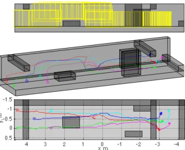
Fig. 8: Results from a 5-robot simulation. The environment is grey, with +y wall removed for clarity. (top) Prisms compos-ing the free space in yellow in a side view. (middle) Isometric view of trajectories. (bottom) Top view of trajectories.
0 0.5 1 1.5 2 2.5 3 3.5 4 4.5 5 0 500 1000 1500 2000 2500
Distance between each pair of robots
time, minutes
distance, mm
Minimum safe distance between robots: 600mm
Fig. 9: Distance between robot pairs in 5-robot simulation. λmin= 600mm is maintained.
A. Simulations
We have tested the system in simulations with up to 5 robots in four different environments. Figure 7 shows the initial, a middle, and final frame of a representative simulation with n = 5 robots in a complex environment as it appears in the bottom left view of the iOS interface. The goal is to maneuver robots through the trench from the left to the right side. In the left frame, the system initiates with a prism enclosing all robots (robots occluded by obstacles are shown with a yellow dot). In the middle frame the user manipulates the prism to navigate it through the environment; the prism need not be large enough to accomodate all robots. In the right frame, all the robots have made it into the final prism. B. Experiments
We ran experiments with up to 3 quadrotors in five environments. Here we show an experiment with n = 3
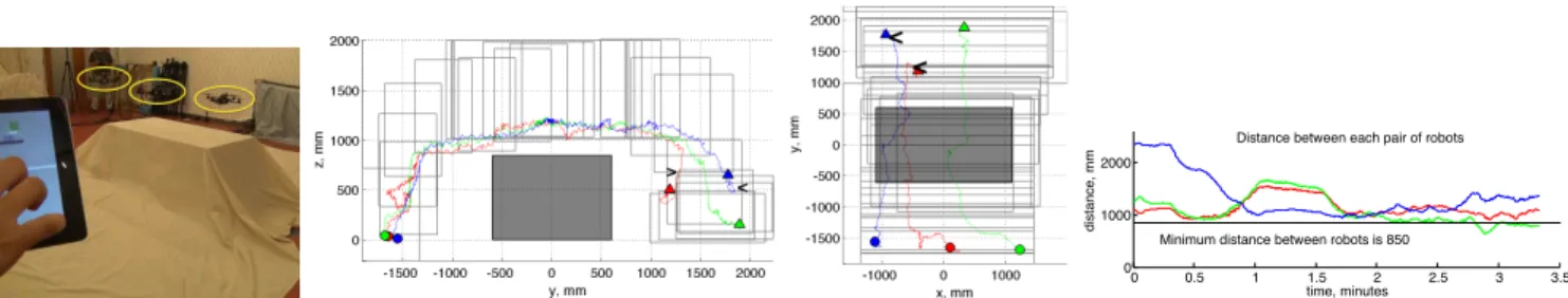
quadrotors in an environment with an obstacle. The envi-ronment and app-generated free space is shown in Fig. 3. In this experiment, three quadrotors rise over the obstacle via translating the prism, change configurations when the prism is scaled, then land on the opposite side of the obstacle via another translation. We use a 12-camera VICON motion capture system [24] for localization, and a linear-quadratic regulator (LQR) takes waypoints and generates low-level commands which are sent to each robot via XBee-Pro.
Isometric and top views of the experiment are shown in Fig. 10. The robots initiate at the colored circles and the reach equilibrium at the triangle marker. The distance between the robots is shown in the panel on the right. One notable result is how much the robots outperform the convergence guarantee. Although we guarantee robots’ reach within a distance (n − 1)λmax of the final prism, which
would be 1700 mm, all robots reach within 200mm of the final prism (red: 40mm, green:inside, blue: 188mm). This is representative of all of our simulations and experiments; the robots get much closer to the final prism than the guarantee. The distance between the farthest robot and the last prism is heavily dependent on the size of the prisms. The smaller the prisms, the less room for robots to fill in the final prism.
There is one interesting result from this run that may at first appear to be cause for concern: one pair of robots break the minimum distance constraint λmin = 850mm (the blue
and red robots in the trajectory plots; the minimum distance between them is 638mm). This is likely a consequence of a number of factors. First, we are implementing a continuous controller (5) on a discrete system, which, to account for noise, updates at a forcibly slow rate. Second and more significantly, the air flow around the quadrotors creates an unmodelled irregular noise that can greatly affect the performance of both robots (850mm is extremely close, as the robots themselves have a radius of 270mm leaving approximately 310mm between the rotors of two robots). Our system does not model the on-board LQR controller, and properly calibrating the LQR gains to account for the expected noise in the system would prevent the robots from getting too close. How to set these gains is outside the scope of this paper, although we note that this is a one-time pre-processing step for a given cluster of robots and set of expected conditions (though such tuning might not be required for all vehicles). It is worth noting that the robots recover gracefully from this failure, demonstrating the robustness of our system.
VIII. DISCUSSION
We have presented a novel distributed control policy for multirobot navigation designed specifically to be synthesized using only inputs from a straightforward, simple multitouch
0 0.5 1 1.5 2 2.5 3 3.5 0
1000 2000
Distance between each pair of robots time, minutes
distance, mm
Minimum distance between robots is 850
Fig. 10: An experiment with three robots. (far left) A photo of the experimental setup. (left ctr) A top view and (right ctr) a side view of the robots’ trajectory, showing only every 4th cube for clarity. (far right) The distances between pairs of robots. The distance for one pair of robots (the pair shown in green, corresponding to the red and blue robots in the trajectory plots), drops below the safety threshold but recovers. In the trajectory plots, <, > mark the location where this occurs. interface created for non-experts. We provide an end-to-end
solution for navigation of a team of robots from one location to another in a constrained environment with obstacles that provides guarantees on convergence and safety with simple multitouch gestures as input. The interface allows the user to decide a general path for the robots, allowing the user to evaluate the quality and risk of different available paths rather than creating a complex controller. This gives the user the ability to determine which risks should be taken and how close robots should get to certain obstacles. Such end-to-end solutions lower the barrier of entry to multirobot systems, enabling even those who have never programmed or used a robot to operate teams of robots.
Although our current system is robust, it does have limitations. Using a single prism to enclose the robots at initialization may not be feasible in some environments, where obstacles may exist between the robots. Merging multiple initial prisms, while resulting in a more complex interface to indicate merging, is a straightforward extension of this work. Splitting into multiple sets of prisms, however, is a more complex problem we plan to investigate. We also plan to incorporate rotations of the prism, which would allow the robots to more easily navigate more complex environments, such as those with ramps.
We have produced a simple interface to demonstrate that a controller that guarantees safety and convergence can be determined using very high-level inputs. The user experience, however, is not fully addressed in this work. Various design choices, e.g. particular gestures and views, remain unevalu-ated at this time. Designing a truly intuitive user interface requires coordinating with experts in the field, as well as extensive user studies. This is a subject of ongoing work.
REFERENCES
[1] L. Parker and B. Emmons, “Cooperative multi-robot observation of multiple moving targets,” in IEEE Intl Conf Robot. Automat., vol. 3, 1997, pp. 2082–2089.
[2] S. Smith and D. Rus, “Multi-robot monitoring in dynamic environ-ments with guaranteed currency of observations,” in IEEE Conf Dec. and Contr., 2010, pp. 514–521.
[3] W. Nguyen and J. Mills, “Multi-robot control for flexible fixtureless assembly of flexible sheet metal auto body parts,” in IEEE Intl Conf Robot. Automat., vol. 3, 1996, pp. 2340–2345.
[4] J. Jang, P.-H. Koo, and S. Y. Nof, “Application of design and control tools in a multirobot cell,” Computers and Industrial Engineering, vol. 32, no. 1, pp. 89 – 100, 1997.
[5] S. Hoshino, H. Seki, Y. Naka, and J. Ota, “Multirobot coordination for flexible batch manufacturing systems experiencing bottlenecks,” IEEE Trans. Autom. Sci. Eng, vol. 7, no. 4, pp. 887–901, 2010.
[6] J. Spletzer, A. Das, R. Fierro, C. Taylor, V. Kumar, and J. Ostrowski, “Cooperative localization and control for multi-robot manipulation,” in IEEE/RSJ Intl Conf Intel. Robots Systems, vol. 2, 2001, pp. 631–636. [7] N. Michael, J. Fink, and V. Kumar, “Cooperative manipulation and transportation with aerial robots,” Autonomous Robots, vol. 30, no. 1, pp. 73–86, 2011.
[8] A. W. Evans, J. P. Gray, D. Rudnick, and R. E. Karlsen, “Control solutions for robots using Android and iOS devices,” in Unmanned Systems Technology XIV, vol. 8387. Proceedings of SPIE, May 2012. [9] M. Micire, M. Desai, A. Courtemanche, K. M. Tsui, and H. A. Yanco, “Analysis of natural gestures for controlling robot teams on multi-touch tabletop surfaces,” in ACM Intl Conf on Interactive Tabletops and Surfaces, ser. ITS ’09, New York, NY, USA, 2009, pp. 41–48. [10] R. T. Fomena, C. P. Quintero, M. Gridseth, and M. Jagersand,
“Towards practical visual servoing in robotics,” in 2013 International Conference on Computer and Robot Vision, no. 28, May 2013. [11] S. Hayes, E. Hooten, and J. Adams, “Multi-touch interaction for
tasking robots,” in ACM/IEEE Intl Conf Human-Robot Interaction, 2010, pp. 97–98.
[12] R. Murphy, “Human-robot interaction in rescue robotics,” IEEE Trans. Syst., Man, Cybern. C, Appl. Rev., vol. 34, no. 2, pp. 138–153, 2004. [13] E. McCann, S. McSheehy, and H. Yanco, “Multi-user multi-touch command and control of multiple simulated robots,” in ACM/IEEE Intl Conf Human-Robot Interaction, 2012, pp. 413–413.
[14] G. Podevijn, R. O’Grady, Y. S. Nashed, and M. Dorigo, “Gesturing at subswarms: Towards direct human control of robot swarms,” IRIDIA, Universite Libre de Bruxelles, Tech. Rep. TR/IRIDIA/2013-006, May 2013.
[15] H. Chen, Y. Kakiuchi, M. Saito, K. Okada, and M. Inaba, “View-based multi-touch gesture interface for furniture manipulation robots,” in IEEE Wkshp Advanced Robotics and its Social Impacts, Half-Moon Bay, Oct. 2011, pp. 39–42.
[16] M. Kloetzer, X. C. Ding, and C. Belta, “Multi-robot deployment from ltl specifications with reduced communication,” in IEEE Conf Dec. and Contr. and European Contr. Conf., 2011, pp. 4867–4872. [17] H. Kress-Gazit, G. Fainekos, and G. Pappas, “Translating structured
english to robot controllers,” Advanced Robotics, vol. 22, pp. 1343– 1359, 2008.
[18] M. Quigley, B. Gerkey, K. Conley, J. Faust, T. Foote, J. Leibs, E. Berger, R. Wheeler, and A. Ng, “ROS: an open-source robot operating system,” in IEEE Intl Conf Robot. Automat. Workshop on Open Source Robotics, Kobe, Japan, May 2009.
[19] E. Rimon and D. Koditschek, “Exact robot navigation using artificial potential functions,” IEEE Trans. Robot. Autom, vol. 8, no. 5, Oct. 1992.
[20] R. Smith, “Open dynamics engine,” 2013.
[21] Imagination Technologies Ltd and J. Lempernesse at KoolFing, “iOS Scene Graph Library: a 3D framework for the iPhone, iPad and iPod Touch (version 1.3.0),” https://github.com/isgl3d/isgl3d/blob/master/ ChangeLog, 2012, [Online, Accessed 13-Sept-2013].
[22] Twisted Matrix Labs, www.twistedmatrix.com, 2013.
[23] C. B. Barber, D. P. Dobkin, and H. Huhdanpaa, “The quickhull algorithm for convex hulls,” ACM Trans. Mathematical Software, vol. 22, no. 4, pp. 469–483, 1996.