HAL Id: hal-01873388
https://hal.laas.fr/hal-01873388
Submitted on 13 Sep 2018HAL is a multi-disciplinary open access archive for the deposit and dissemination of sci-entific research documents, whether they are pub-lished or not. The documents may come from teaching and research institutions in France or abroad, or from public or private research centers.
L’archive ouverte pluridisciplinaire HAL, est destinée au dépôt et à la diffusion de documents scientifiques de niveau recherche, publiés ou non, émanant des établissements d’enseignement et de recherche français ou étrangers, des laboratoires publics ou privés.
Hydrous RuO2 /carbon nanowalls hierarchical
structures for all-solid-state ultrahigh-energy-density
micro-supercapacitors
Ty Mai Dinh, Amine Achour, Sorin Vizireanu, Gheorghe Dinescu, Leona
Nistor, Kevin Armstrong, Daniel Guay, David Pech
To cite this version:
Ty Mai Dinh, Amine Achour, Sorin Vizireanu, Gheorghe Dinescu, Leona Nistor, et al.. Hydrous RuO2 /carbon nanowalls hierarchical structures for all-solid-state ultrahigh-energy-density micro-supercapacitors. Nano Energy, Elsevier, 2014, 10, pp.288 - 294. �10.1016/j.nanoen.2014.10.003�. �hal-01873388�
Hydrous RuO
2/carbon nanowalls hierarchical structures for all-solid-state
ultrahigh-energy-density micro-supercapacitors
Ty Mai Dinha,b,1, Amine Achoura,b,1, Sorin Vizireanuc, Gheorghe Dinescuc, Leona Nistord,
Kevin Armstronge, Daniel Guaye, and David Pecha,b,*
aCNRS, LAAS, 7 avenue du colonel Roche, F-31400 Toulouse, France.
bUniv de Toulouse, LAAS, F-31400 Toulouse, France.
cNational Institute for Laser, Plasma and Radiation Physics, Magurele, Bucharest, 077125
Romania.
dNational Institute for Materials Physics, Magurele, Bucharest, 077125 Romania.
eINRS-Énergie, Matériaux, Télécommunications, 1650 boulevard Lionel Boulet, J3X 1S2
Varennes, Québec, Canada.
*Corresponding author. Tel.: +33 5 61 33 68 37. E-mail adress : dpech@laas.fr (D. Pech).
Abstract
Micro-supercapacitors have attracted considerable research attention for on-chip energy storage due to their unique properties and potential applications in various smart electronic devices. Although significant advances have been reported on their power performances, they still cannot compete with micro-batteries in terms of energy densities for mobile, portable and self-powered applications. Herein, we demonstrate the fabrication of vertically aligned carbon nanowalls (CNW) decorated with porous ruthenium oxide as a high-performance electrode for all-solid-state micro-supercapacitors. The decorated CNW electrode, essentially consisting of thin carbon sheets assembled from graphene domains, delivers specific capacitance in excess of 1000 mF cm-2 (which is three orders of magnitude higher than state-of-the-art
micro-supercapacitors) and energy density comparable to that of lithium-ion micro-batteries, but with superior power and cycling stability. Our findings demonstrate a route towards the integration of microfabricated supercapacitors combining fast charge/discharge rates with high energy densities.
Introduction
The increasing importance of portable and wearable devices incorporating more advanced electronic technologies, as well as the future deployment of wireless sensor networks embedded in our everyday environment has made on-board energy storage a critical issue [1]. In the last decade, the integration of miniaturised electrochemical capacitors (also called supercapacitors) on circuit chips has been the subject of intense research on the account of their excellent charge-discharge rate and long operating life time [2-7]. Although ultrahigh-power micro-sized supercapacitors have been reported [8-14], they still suffer from low energy density that remains far from Li-ion micro-batteries [15-17]. A significant improvement of their volumetric/areal energy density is needed for more challenging applications.
Supercapacitors can be divided into two categories, depending on their charge-storage mechanism. The most common devices rely on the capacitive behaviour of high surface area carbon-based materials. The second category relies on the fast and reversible faradaic surface reactions of pseudo-capacitive materials, mainly transition metal oxides. Hydrous forms of ruthenium dioxide (hRuO2) currently represent the state of the art among pseudo-capacitive
materials, with the highest reported specific capacitance [18]. Its high cost has limited its development for large-size supercapacitors, but the use of this material becomes relevant and promising for micro-supercapacitors as very little amount of active material is required. Moreover, the capacitance of hRuO2 can be further increased by deposition onto a
nanostructured conductive support with high surface area such as carbon nanotubes [19], graphene [20,21] or porous gold [22].
Carbon nanowalls (CNW), also named vertically oriented graphene sheets, are among the most promising materials in the carbon family. They can be described as three-dimensional
networks of vertically standing, interconnected 2-D nanostructures consisting of graphene domains overlapping each other. This graphene-based architecture with vertical wall orientation, sharp edges and open structure is associated with a large surface area (in the range of 100- 1500 m2 g-1) [23], good electronic conductivity [24] and excellent chemical stability [25]. These
combined properties make carbon nanowalls superior for various electrochemical applications. Indeed, this nanostructured material has already been adopted in the semiconductor technology, but there have been very few reports for energy storage applications [26,27].
Herein, we demonstrate a new hybrid material based on capacitive CNW decorated with pseudo-capacitive hRuO2. By adjusting the experimental synthesis conditions of the CNW and
the electrodepositon parameters of hRuO2, we achieved an outstanding specific capacitance of
1097 mFcm-2, which is three orders of magnitude higher than state-of-the-art graphene based
micro-supercapacitors [11]. Therefore, hRuO2-decorated CNW electrode could be used to
fabricate miniaturized energy-storage devices that bridge the massive energy density gap between supercapacitors and batteries, while still retaining extended lifetime and huge power density.
Materials and methods
Fabrication of the composite electrode
An insulating Si3N4 layer (80 nm) was first deposited on a silicon wafer. Current collectors were
then deposited using the evaporation of a 40 nm Cr/200 nm Pt layer. The CNW layers growth was carried out by PECVD in a Ar/H2/C2H2 radiofrequency plasma jet [28]. The plasma source
operated at 400 W power, and 1400 sccm gas flow rate was used to produce, via a nozzle, a directional argon jet in the deposition chamber. Acetylene (1 sccm) and hydrogen (25 sccm)
were injected into this jet through a ring placed downstream the nozzle. The deposition proceeded on the heated substrate (700 oC) placed at 5 cm from the injection ring at a pressure of
1.3 mbar.
Electrodeposition of hydrous ruthenium oxide onto the CNW support was afterwards carried out from an aqueous chloride solution composed of 10 mM RuCl3.xH2O in 10-1 M KCl / 10-2 M HCl,
and adjusted to pH=2.5 with a 2M KOH aqueous solution. Cyclic voltammetry (CV) between -300 and +950 mV vs. saturated Ag/AgCl at 50 mV s-1 and performed at 50°C for various
number of cycles under stirring conditions was used to induce the growth of the hRuO2 deposits.
All samples were annealed under air at 150°C for 1 h.
The PVA-H3PO4-SiWA polymer precursor solution was prepared by mixing a poly(vinyl
alcohol) (PVA, Mw =31 000-50 000, 87-89 % hydrolyzed) solution with phosphoric acid
(H3PO4) and SiWA (H4SiW12O40) in a composition of 1.7 wt.% PVA, 1.9 wt.% H3PO4,
14.4 wt.% SiWA and 82 wt.% de-ionized water. The conductivity of the solid electrolyte was 6.1 mS cm-1 after 24 h (22.2°C - 32 % RH).
Material characterization
Scanning electron microscopy (SEM) was performed using a Hitachi S-4800 field-emission electron microscope, and high resolution transmission electron microscopy (HRTEM) using an atomic resolution analytical Jeol JEM-ARM 200F electron microscope operating at 200 kV. Specimens for TEM observations were prepared by extracting CNW/RuO2 film flakes and
transferring them on holey carbon grids. The Raman spectrum was recorded at 532 nm laser excitation wavelength, using a Jasco NRS 7200 apparatus. The surface chemical composition of
ruthenium oxide was estimated via X-ray Photoelectron Spectroscopy (XPS) using a Thermo Scientific spectrometer operating with a monochromatic AlKα X-ray source (1486.6 eV).
Electrochemical characterization
The electrochemical characterizations were performed with a SP-240 potentiostat from BioLogic. A three-electrode electrochemical cell with a platinum gauze counter-electrode and a saturated Ag/AgCl reference-electrode in de-aerated 0.5 M H2SO4 electrolyte at room
temperature was used for the electrode characterization (exposed area 1 cm2), and a
two-electrode cell with a PVA-H3PO4-SiWA solid electrolyte for the device. Electrochemical
Impedance Spectroscopy measurements were carried out at open circuit potential in the 100kHz
to 10mHz frequency range. The accessibility of the electrolyte to the electroactive material has been investigated by calculating the voltammetric charge (q*) as a function of the sweep rates (v)
according to a procedure developed by Trasatti [29,30]. The value of the outer capacitance (Co)
has been obtained from the extrapolation of q* to v = ∞ from the plot of q* vs. v-½, whereas the
total capacitance (Ct) has been estimated from the extrapolation of q* to v = 0 from the plot q*-1
vs. v½.
Results and discussion
Figure 1a shows the top-view scanning electron microscope (SEM) image of a CNW layer deposited on a silicon wafer (which was precoated with a thin platinum film). The cross-section (inset) shows a 12-μm thick uniform porous film (height of the CNW), with the carbon sheets vertically oriented with respect to the surface of the substrate. It can also be noted that the open spaces between the carbon sheets extend across the layer from the top to the bottom. The porous
honeycomb structure consists of interconnected carbon sheets with lengths of 1-2 μm (top view SEM) and thicknesses of 10-50 nm. The graphene-type structure of the CNW is confirmed by Raman spectroscopy (Figure S1) and transmission electron microscopy (TEM) images (Figure S2). With electrodeposition, the CNW were covered in-depth, up to 6-7 µm, with the pseudo-capacitive hydrated RuO2 particles (Figure 1b and S3). The particles have sizes in the range of
hundreds of nanometers and are agglomerated in a cauliflower morphology (Figure 1b, S3 and S4). The nature of the electrodeposited layer is demonstrated by electron diffraction (inset of Figure S2a) and XPS (Figure S5). The porous structure of CNW and its high flexibility offer not only paths for electrolyte penetration, but also space for the volume expansion of the hRuO2
material without any damage of the connectivity between the grains and the CNW, as represented in the schematic in Figure 1c. An intimate contact between the hRuO2 particles and
the CNW is observed in the cross-section SEM micrograph hRuO2/CNW layered structure
(Figure 1b). The interface between the two material types, distinguishable by their different morphology, is not actually defined. This was confirmed by high resolution TEM investigations (Figure 1d and S2): the RuO2 nanoparticles with sizes of 1-3 nm lie on the graphene sheets
composing the CNW (the amorphous hRuO2 nanoparticles display crystalline characteristic as a
result of their transformation upon irradiation by the e-beam of the microscope). Moreover, the hRuO2 particles are distributed evenly, indicating the existence of a large connective area
Figure 1 (a) Scanning electron microscope (SEM) image of a 12 µm-thick CNW film; inset: cross-section revealing the vertically aligned morphology of the CNW film. (b) Cross-section
SEM image of a CNW film (bottom) on which hRuO2 has been electrodeposited on its top. The
two materials are distinguishable by their different morphology (cauliflower vs. vertically aligned). (c) Schematic of the vertically-aligned CNW decorated with hRuO2 particles. (d) High
resolution transmission electron microscopy (HRTEM) image showing the RuO2 nanoparticles
(some marked with white arrows), lying on the lateral faces (marked 1) and edges (marked 2) of
hRuO2particles 12 µm 1 µm
a
c
b
d
5.6 µm 6.4 µm hRuO2on CNW CNW 3 µm 10 nmthe CNW; black arrows indicate the lattice fringes of the (002) crystallographic planes visible at the CNW-edges (for more information see Figure S2).
The electrochemical performances of the CNW with thicknesses ranging from 900 nm to 12 µm were evaluated using cyclic voltammograms (CV). The specific capacitance of the CNW films increases with increasing thickness, up to 5.7 mF cm-2 for the 12 µm-thick CNW (Figure
S6). This value is very close to the value of 18.3 mF cm-2 obtained by A. Achour et al. with
titanium nitride/carbon nanotubes electrodes, which is the highest specific capacitance reported for electrodes in micro-supercapacitors [31,32].
Figure 2 Electrochemical characterization of a CNW/hRuO2 electrode. (a) CV of the 12
µm-thick CNW before and after hRuO2 electrodeposition in de-aerated 0.5 M sulfuric acid
electrolyte. (b) Variation of the voltammetric charge (q*) with respect to the sweep rates.
Furthermore, high surface area hRuO2 was afterwards synthesized using a 12 µm-thick
CNW as a template (Figure S7).To our surprise, this hRuO2/CNW hybrid electrode exhibited an
extremely high capacitance of 1094 mF cm-2 when cycled at 2 mV s-1 in sulfuric acid electrolyte
(Figure 2a), which is to our knowledge, an unprecedented performance for a microfabricated
0.0 0.2 0.4 0.6 0.8 1.0 -3 -2 -1 0 1 2 3 hRuO 2 on CNW CNW 2 mV s-1 Current (mA cm -2) Potential (mV vs. Ag/AgCl) a b 0 1 2 3 4 0.0 0.5 1.0 1.5 2.0 0 1 2 3 0.0 0.4 0.8 1.2 Ct = 1239 mF cm-2 Co = 1005 mF cm-2 q *-1 ( cm 2 C -1) v1/2 (mV/s)1/2 q * ( C cm -2) v-1/2 (s/mV)1/2
supercapacitor electrode. The value of the outer capacitance (Co), which is related to the more
accessible active surface, reaches 1005 mF cm-2 for a total capacitance (C
t) of 1239 mF cm-2
(Figure 2b) [29]. This value is three orders of magnitude higher than that of the state-of-the-art graphene based micro-supercapacitors (0.3 mF cm-2 electrode capacitance) [11], and far larger
than most micro-supercapacitor electrodes based on other advanced materials (Figure 3) [33-37].
Figure 3 Comparison of the hybrid CNW/hRuO2 electrode capacitance with the electrode
capacitance of state-of-the-art micro-supercapacitors. (A factor of 4 has been taken into account between the electrode and the cell capacitance).
Figure S3 shows, for comparison, the morphology of a hRuO2 thin film deposited on a
flat gold substrate using the same experimental conditions. Its thickness is identical to the one deposited on CNW. The deposition kinetics does not seem modified by a change of the substrate, with a hRuO2 able to grow on a large surface area. The Co/Ct ratio of the CNW/hRuO2 electrode
(81 %) is also very close (and even higher) than the one obtained with hRuO2 deposited on flat 0 200 400 600 800 1000 1200 hRuO2on CNW CNT : Carbon Nanotube RGO : Reduced Graphite Oxide OLC : Onion-Like Carbon CNW : Carbon NanoWall CDC : Carbide Derived Carbon
gold substrate (71 %, Figure S8), indicating that, irrespective of the substrate differences for these two electrodes, most of the total storable charge is rapidly accessible.
Figure S9 shows the Nyquist plots in sulfuric acid electrolyte for the CNW before and after hRuO2 electrodeposition. For both samples, no leakage current is observed, with a near
vertical straight line in the low-frequency region typical of a capacitive behaviour. A negligible equivalent distributed resistance (EDR) and an equivalent series resistance (ESR) of 11.8Ωcm2
were estimated from the high frequency part of the spectrum of the hRuO2-free CNW. The ESR
slightly decreased to 8Ωcm2 when decorated with conductive hRuO2, leading to a maximum
specific power of 31.3mWcm-2.
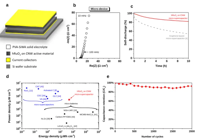
Figure 4 Charaterization of a solid-state micro-supercapacitor based on CNW/hRuO2. (a)
Schematic diagram of on-chip micro-supercapacitor with 2D architecture. (b) Nyquist plot and
0 2 4 6 8 10 0 20 40 60 80 100 Graphene-based micro-supercapacitor [4] hRuO2 on CNW micro-supercapacitor Self-disch arge (%) Time (h) 0 500 1000 1500 2000 0% 20% 40% 60% 80% 100% Cap aci tance retention (C/ Co ) Number of cycles 10-2 10-1 100 101 102 103 104 100 101 102 103 104 105 106 107 VN [45] micro-batteries MCMB-MoOySz [41] micro-supercapacitors RuO2 [12] CDC [34] OLC [44] CNT [43] Activated C [8] NiSn-LMO [16] Carbon-PPYDBS [40] LiCoO 2-Li4Mn5O12 [42] Ni-Zn [39] Po wer den sity ( W cm -2) Energy density (Wh cm-2 ) hRuO2 on CNW micro-supercapacitor
hRuO2on CNW active material
PVA-SiWA solid elecrolyte
Si wafer substrate Current collectors 00 20 40 60 80 20 40 60 80 100 mHz 10 mHz -Im( Z) ( cm 2) Re(Z) ( cm2) Micro-device a b c d e
(c) self-discharge curve of the micro-device. (d) Comparison, in a Ragone plot, of the specific energy and power density of the CNW/hRuO2-based micro-supercapacitor with state-of-the-art
micro-supercapacitors and micro-batteries. (e) Evolution of the relative capacitance vs. the number charge/discharge cycles at 1.5 mA cm-2.
Vertically-aligned CNW/hRuO2 electrode has been employed to realize an-all-solid-state
micro-supercapacitor in a stack configuration using a silicon wafer as a substrate (Figure 4a). An innovative solid-polymer electrolyte [38], composed of polyvinyl alcohol (PVA), orthophosphoric acid (H3PO4) and silicotungstic acid (SiWA) was used to act as a separator and
ionic conductor without leakage issues and very low ESR (Figure 4b). The micro-device exhibits also a very low self-discharge (less than 18 % voltage drop after 10 h, Figure 4c), lower than that of a graphene-based micro-supercapacitor, which is known for good energy retention [4].
To demonstrate the overall performance of the solid-state micro-supercapacitor, a Ragone plot is shown Figure 4d [39-45]. Remarkably, this solid-state CNW/hRuO2 micro-supercapacitor
delivered a specific energy density of 49 µWh cm-2 (i.e. 2 µWh cm-2 µm-1), which is higher than
recent work reported for micro-supercapacitors [8, 12, 34, 43-45] and comparable to the state-of-the-art lithium ion micro-batteries [16, 39-42], but with much higher power and much higher lifetime (up to 2000 cycles of galvanostatic charge/discharge at 1.5 mA cm-2, Figure 4e and
Figure 5 Galvanostatic charge/discharge curves at 1.5 mA cm-2 at different cycles of a
solid-state CNW/hRuO2-PVA/SiWa-CNW/hRuO2 micro-supercapacitor. (a) 1st cycle. (b) 100th
cycle. (c) 1000th cycle. (d) 2000th cycle.
Conclusions
The use of vertically-aligned CNW decorated with hRuO2 particles offers an exceptional
potential for micro-supercapacitors by patterning such electrode onto silicon wafers with standard microelectronic processes. For the first time, it is showcased that micro-supercapacitors can compete, in term of specific energy, with micro-batteries to power microelectronic devices such as wireless sensor nodes, active radiofrequency identification (RFID) tags and embedded micro-sensors. These applications can be extended to larger devices by scaling up the electrode
0 100 200 300 400 0.0 0.2 0.4 0.6 0.8 1.0 Vol ta ge (V) Cycle 2000 Cycle 1000 Cycle 100 Cycle 1 Vol ta ge (V) 0 100 200 300 400 0.0 0.2 0.4 0.6 0.8 1.0 0 100 200 300 400 0.0 0.2 0.4 0.6 0.8 1.0 0 100 200 300 400 0.0 0.2 0.4 0.6 0.8 1.0 Time (s) Time (s) a b c d
surface. Further improvements and optimization of the electrodeposition process for the hRuO2
should also allow a substantial increase of the capacitance and energy of the device.
Acknowledgments
This work was financially supported by the French National Research Agency (ANR) through the MIDISTOCK project and the Ministry of National Education of Romania (CNCS – UEFISCDI, project numbers PN-II-ID-PCE-2012-4-0629 and PN-II-ID-PCE-2012-4-0362). One of us (D.G.) would like to acknowledge the financial support of the Canada Research Chair program.
Appendix. Supplementary materials
Supplementary data associated with this article can be found in the online version.
References
[1] Z.L. Wang, Adv. Mater. 24 (2012) 280-285.
[2] J. Chmiola, C. Largeot, P.L. Taberna, P. Simon, Y. Gogotsi, Science 328 (2010) 480-483. [3] W. Gao, N. Singh, L. Song, Z. Liu, A.L. Mohana Reddy, L. Ci, R. Vajtai, Q. Zhang, B. Wei, P.M. Ajayan, Nat. Nanotech. 6 (2011) 496-500.
[4] M.F. El-Kady, R.B. Kaner, Nat. Comm. 4 (2012) 1475.
[5] Q. Meng, H. Wu, Y. Meng, K. Xie, Z. Wei, Z. Guo, Adv. Mater. 26 (2014) 4100-4106. [6] I. Nam, G.P. Kim, S. Park, J.W. Han, J. Yi, Energy Environ. Sci. 7 (2014) 1095-1102. [7] S.K. Kim, H.J. Koo, A. Lee, P.V. Braun, Adv. Mater. 26 (2014) 5108-5112.
[8] D. Pech, M. Brunet, H. Durou, P. Huang, V. Mochalin, Y. Gogotsi, P.L. Taberna, P. Simon, Nat. Nanotech. 5 (2010) 651-654.
[9] K. Sheng, Y. Sun, C. Li, W. Yuan, G. Shi, Sci. Rep. 2 (2012) 247. [10] A. Ghosh, V.T. Le, J.J. Bae, Y.H. Lee, Sci. Rep. 3 (2013) 2939. [11] Z.-S. Wu, K. Parvez, X. Feng, K. Müllen, Nat. Comm. 4 (2013) 2487.
[12] D. Pech, M. Brunet, T.M. Dinh, K. Armstrong, J. Gaudet, D. Guay, J. Power Sources 230 (2013) 230-235.
[13] T.M. Dinh, K. Armstrong, D. Guay, D. Pech, J. Mater. Chem. A 2 (2014) 7170-7174. [14] Z.S. Wu, K. Parvez, X. Feng, K. Müllen, J. Mater. Chem. A 2 (2014) 8288-8293. [15] H. Zhang, X. Yu, P.V. Braun, Nat. Nanotech. 6 (2011) 277-281.
[16] J.H. Pikul, H.G. Zhang, J. Cho, P.V. Braun, W.P. King, Nat. Comm. 4 (2013) 1732. [17] N.A. Kyeremateng, ChemElectroChem 1 (2014) 1442-1467.
[18] W. Deng, X. Ji, Q. Chen, C.E. Banks, RSC Adv. 1 (2011) 1171-1178. [19] P. Simon, Y. Gogotsi, Nat. Mater. 7 (2008) 845-854.
[20] Z.S. Wu, G. Zhou, L.C. Yin, W. Ren, F. Li, H.M. Cheng, Nano Energy 1 (2012) 107-131. [21] W. Wang, S. Guo, I. Lee, K. Ahmed, J. Zhong, Z. Favors, F. Zaera, M. Ozkan, C.S. Ozkan, Sci. Rep. 4 (2014) 4452.
[22] X. Lang, A. Hirata, T. Fujita, M. Chen, Nat. Nanotech. 6 (2011) 232-236.
[23] T.C. Hung, C.F. Chen, W.T. Whang, Electrochem. Solid-State Lett. 12 (2009) K41-K44. [24] D.H. Seo, S. Kumar, K. Ostrikov, Carbon 49 (2011) 4331-4339.
[25] S. Vizireanu, G. Dinescu, L.C. Nistor, M. Baibarac, G. Ruxanda, M. Stancu, D. Ciuparu, Physica E 47 (2013) 59-65.
[26] Z. González, S. Vizireanu, G. Dinescu, C. Blanco, R. Santamaría, Nano Energy 1 (2012) 833-839.
[28] S. Vizireanu, S.D. Stoica, C. Luculescu, L.C. Nistor, B. Mitu, G. Dinescu, Plasma Sources Sci. Technol. 19 (2010) 034016.
[29] S. Ardizzone, G. Fregonara, S. Trasatti, Electrochim. Acta 35 (1990) 263-267. [30] D. Baronetto, N. Krstajić, S. Trasatti, Electrochim. Acta 39 (1994) 2359-2362.
[31] A. Achour, J.B. Ducros, R.L. Porto, M. Boujtita, E. Gautron, L. Le Brizoual, M.A. Djouadi, T. Brousse, Nano Energy 7 (2014) 104-113.
[32] M. Beidaghi, Y. Gogotsi, Energy Environ. Sci. 7 (2014) 867-884. [33] L. Wei, N. Nitta, G. Yushin, ACS Nano 7 (2013) 6498-6506.
[34] P. Huang, M. Heon, D. Pech, M. Brunet, P.L. Taberna, Y. Gogotsi, S. Lofland, J.D. Hettinger, P. Simon, J. Power Sources 225 (2013) 240-244.
[35] B. Hsia, M.S. Kim, M. Vincent, C. Carraro, R. Maboudian, Carbon 57 (2013) 395-400. [36] M. Beidaghi, C. Wang, Adv. Funct. Mater. 22 (2012) 4501-4510.
[37] C. Shen, X. Wang, W. Zhang, F. Kang, Sci. Rep. 3 (2013) 2294. [38] H. Gao, K. Lian, J. Mater. Chem. 22 (2012) 21272-21278.
[39] F. Chamran, Y. Yeh, H.S. Min, B. Dunn, C. Kim, J. Microelectromechanical Syst. 16 (2007) 844-852.
[40] H.S. Min, B.Y. Park, L. Taherabadi, C. Wang, Y. Yeh, R. Zaouk, M.J. Madou, B. Dunn, J. Power Sources 178 (2008) 795-800.
[41] M. Nathan, D. Golodnitsky, V. Yufit, E. Strauss, T. Ripenbein, I. Shechtman, S. Menkin, E. Peled J. Microelectromechanical Syst. 14 (2005) 879-885.
[42] M. Kotobuki, Y. Suzuki, H. Munakata, K. Kanamura, Y. Sato, K. Yamamoto, T. Yoshida, Electrochim. Acta 56 (2011) 1023-1029.
[44] P. Huang, D. Pech, R. Lin, J.K. McDonough, M. Brunet, P.L. Taberna, Y. Gogotsi, P. Simon, Electrochem. Comm. 36 (2013) 53-56.
[45] E. Eustache, R. Frappier, R.L. Porto, S. Bouhtiyya, J.F. Pierson, T. Brousse, Electrochem. Comm. 28 (2013) 104-106.