Publisher’s version / Version de l'éditeur:
Vous avez des questions? Nous pouvons vous aider. Pour communiquer directement avec un auteur, consultez la première page de la revue dans laquelle son article a été publié afin de trouver ses coordonnées. Si vous n’arrivez pas à les repérer, communiquez avec nous à PublicationsArchive-ArchivesPublications@nrc-cnrc.gc.ca.
Questions? Contact the NRC Publications Archive team at
PublicationsArchive-ArchivesPublications@nrc-cnrc.gc.ca. If you wish to email the authors directly, please see the first page of the publication for their contact information.
https://publications-cnrc.canada.ca/fra/droits
L’accès à ce site Web et l’utilisation de son contenu sont assujettis aux conditions présentées dans le site LISEZ CES CONDITIONS ATTENTIVEMENT AVANT D’UTILISER CE SITE WEB.
Technical Memorandum (National Research Council of Canada. Associate
Committee on Soil and Snow Mechanics); no. DBR-TM-51, 1957-10
READ THESE TERMS AND CONDITIONS CAREFULLY BEFORE USING THIS WEBSITE. https://nrc-publications.canada.ca/eng/copyright
NRC Publications Archive Record / Notice des Archives des publications du CNRC :
https://nrc-publications.canada.ca/eng/view/object/?id=e3358805-4c50-4f8c-8315-b86d7df7004c
https://publications-cnrc.canada.ca/fra/voir/objet/?id=e3358805-4c50-4f8c-8315-b86d7df7004c
NRC Publications Archive
Archives des publications du CNRC
This publication could be one of several versions: author’s original, accepted manuscript or the publisher’s version. / La version de cette publication peut être l’une des suivantes : la version prépublication de l’auteur, la version acceptée du manuscrit ou la version de l’éditeur.
For the publisher’s version, please access the DOI link below./ Pour consulter la version de l’éditeur, utilisez le lien DOI ci-dessous.
https://doi.org/10.4224/40001218
Access and use of this website and the material on it are subject to the Terms and Conditions set forth at
Engineering problems involving pre-consolidated clay shales
NATIONAL RESEARCH COUNCIL OF CANADA
ASSOCIATE COMMITTEE ON SOIL AND SNOW MECHANICS
buャ「ュnセ
RESEARCH
..
ャャ・セary
..
aHSセ
2
1958
ENGINEERING PROBLEMS INVOLVING
PRE-CONSOLIDATED CLAY SHALES
ANAL VIED
R.
M. Hardv
.IDean of the Faculty of Engineering
University of Alberta
Paper presented at the Tenth Canadian Soil セi・」ィ。ョゥ」ウ Conference held und-r the auspices of the Associate Committee on Soil and SnowMcclianics, Nntionul Research Council of Canada, Ottawa, 17 and 18 December, 1956.
REPRINTED FROM TRANSACTIONS OF THE
E1'\GINEERING INSTITUTE OF CANADA, NO. 1 SEPTEMBER 1957
TECHNICAL MEMORANDUM NO. 51
The Associate Committee on Soil and Snow Mechunics is one of about thirty special committees icliicl: assist the National Research Council in its icork. Formed in 1945 to deal uiith an urgent icartime problem incoloirui soil and snOlC, the Committee is nOlC performing its intended task of co-ordinating Canadian research studies concerned with the physical and mechanical properties of the terrain of the Dominion. It does this through subcommittees all Snotc and Ice, Soil Mechanics, Muskeg, and
Permafrost. The Committee, uihicl, consists of about fifteen Canadians appointed as ituliciduals and not as representatices, each for a 3-year term, has funds acoilable to it for making research grants for icork in its [lelds of interest. Inquiries icill be Ice/corned and should be addressed to: The Secretary, Associate Committee on Soil and Snow M echunics, c/o The Dicision of Building Research, National Research Council, Ottaica, Canada.
Engineering Problems Involving
Pre-Consolidated Clav Shales
.'
R. M. Hardy,
M.E-I.e.Dean of the Fuculiu of Engineering, Unit'ersity of Alberta
G
E OLOGI CALLY shale is a laminated sediment('01\1-posed principally of clay-sized particles. It is formed by diagenetic processes including consolidation under oyer-burden pressure and the various chemical reactions, both organic and inorganic, which result in the production of cementing compounds. Shales arc intermediate between day and slate in general stability characteristics. They are rocks from the geological point of view but exhibit an extremely wide variation in properties of significance in engineering practice.
Over extensive areas on the North American continent lying in a strip several hundred miles wide to the eastof the Rocky Mountains shales occur in which the major diagenetic process in their formation has been overburden pressure. These shales now exist at overburden pressures much reduced from the maximum which has occurred in their geological history. Under these reduced pressures they tend to revert to clays. The process is accelerated by the availability of subsoil moisture and weathering action including freezing and thawing. Sueh shales are designated as clay shales and they exhibit the properties of soils which are known in the field of soil mechanics as pre-consolidated, or sometimes over-consolidated clays. More generally they have frequently been included in the definition of fissured clays.
This paper deals with engineering experience, particularly in regard to landslides, with such clay shales occurring in the Alberta area, north-eastern British Columbia and the foot-hills section of the Yukon Territory. These are of Cretaceous age and occur interbedded with coal seams, silt, sand, silt-stones, and sandstones having a wide variation in quality of cementing media. Many of them have an appreciable organic content.It is estimated that these deposits have been sub-jected to loads of at least1,,')00 feet of sediments and ice in addition to their present overburden during the various periods of glaciation since their original deposition. They now frequently lie under a shallow overburden of recent deposits usually not exceeding more than a few feet in thick-ness and extend to depths of hundreds of feet. The major rivers in the area have eroded through these beds to depths of as much as600 feet.
Some geologists report thick beds of glacio lacustrine deposits of clays in the general area under consideration. The principal alteration in the characteristics of these soils since their deposition has been due to overburden pressure, and they may now exist, particularly in the river valleys, under much reduced pressures. They thus are pre-consolidated deposits and the same types of engineering problems may occur with these as with the older over-consolidated clay shales.
These particular clay shales contain a high percentage of montmorillonite type clay mineral. Such day minerals have the property of taking lip water into their molecular structure to an extraordinary degree if moisture is available and the soil is at a reduced overburden pressure. "Under these
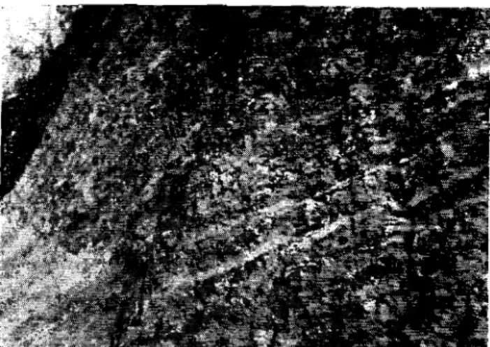
con-ditions the shale reverts to a day of medium to high plas-ticity and in the process is capable of exerting high swelling pressures. The disintegration may also be accompanied by the formation of extensive slickensides in the soil. These properties result in unusual problems in a wide variety of engineering practice in the areas of occurrence of such soils. Figure1shows a typical exposure of these materials along the valley of the Athabasca River. In this particular example the bedding planes arc comparatively thin. The thickness of the various strata however varies widely.
Figure2 shows a plot on the plasticity chart of limit values for representative samples of the clay shales from widely dispersed locations over the area under consideration.
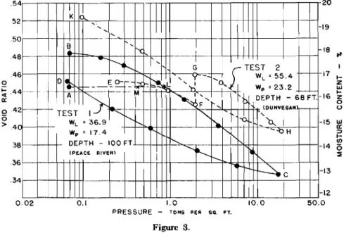
Amongst the soil tests used in the field of soil mechanics the consolidation test most effectively illustrates the peculiar characteristics of these materials. Figure 3shows pressure-void ratio curves from tests on two typical pre-consolidated clay shales. For test 1the sample was subjected to a small load and permitted to take up water freely. Under these con-ditions the sample expanded from A to B. The load on the sample was then increased in increments, each load being left on for sufficient time to permit primary consolidation to be complete in the conventional manner for this test. During this portion of the test the sample consolidated along the line B to C. The load was then removed in increments with sufficient time being permitted between change in loading for the primary expansion, or rebound, to occur. Rebound occurred along the line C to D in this portion of the test. For test 2 the sample was loaded in increments at its natural moisture content without the sample having access to additional free water. During this portion of the test the sample consolidated along the line E to F. At a load closely equal to the submerged overburden weight the sample was given access to free water.It then expanded along the line F to G..After expansion was complete under these conditions loading was continued in increments as in the conventional test. During this stage the sample consolidated along the line G toH.The load was then removed in increments as was done in test 1 and the sample rebounded along the line H to K.
Of particular significance in these two test results are the swelling characteristics and the high degree of rebound exhibited by these typical clay shales. Moreover it should be noted that the magnitude of the rebound for equal increments of decrease in load increases at lower effective pressures.It also appears from the portion F-G of the curve for test 2 that this soil is in equilibrium in its natural state under a deficiency in moisture. Therefore, if by some mechanism, it should suddenly have access to free water it would be capable of expanding under its present overburden pressure. The deformations accompanying the loadings in these two tests are made up partly of elastic strain and partly of primary consolidation. Deformation due to secondary
con-Fig. I-Typical exposure of overconsolidated soils along the valley of the Athabasca River, Alberta.
solidation ゥセ of negligible ruuount. However with prl'-consolidated clays a high perceutage of the deformation may be elastic and OCCUl' instantuneonsly with change in load. For example for the material of test 2 in Fig. ::I a stress-deformation test run quickly in a consolidometcr so that no appreciable consolidation could occur gave an elastic modulus of deformation of 5.000 lb. per sq. in. (400tons per sq. ft.)
for loads up to about -I- tons per sq. ft. With this modulus of
deforruation the elastir- movement would bp about half of
100
x 80
w
c z
behaviour of such soils under ficld coudit.ious uuiv 「Hセ grcatly affected by variations ill subsoil seepage conditions or changes to these which mav hr- caused 1IセN coustruction operations, Desiccation of the soil during coustruction may also produce major・ィ。ョァ・セ to the soil. In these circumstances the laboraturv エ・セエ data mav bl' of little assistance other than to indicatl' tlu- nature of t lu- probleu» that should be given utteution.
Obviouslv if'1day shall' will swell it is capable of exerting swelling pressure. If tile load aud moisture conditions are known laboratory test results such as shown in Fig. 3 can be used to ・セエゥュ。エ・ iuovenu-nts which will O('('l1L However
situntions arise ill which it mav he or。ウセェウエZiャャcHL to know the order of uuumitud« of tln- セキ・ャャゥャャァ prc-sur« which a day shale can exert at a givou initial moisture- CUll tent , This is particularlv true in respect to til(' desiccated or partially desiccated condit.ion,
Refcrring to test 1 in Fig. [セL tlu- pressul'(' for point L is the load whichゥセ required to reducet.h«void ratio to the same value as init.iallv at point A before t h« sample was permitted to swell along the liuo A-B. TIlt' load eoordinutr-for point L is therefore a measure of til!' swelling Ill'CSSIlI'(' of the soil.
This procedure has the adnilltage that it ヲゥエセ ill readily to the routine procedure for running consolidation «'sts. How-ever it has been claimed that「セG pel'lilittingth« soil to take up water freely at 10\\' unit pressur« tlu-erv-tul structure of the soil minerals is altered which lIwans that tllP funda-mcntal nuturo oftil(' soil is changed.
/
o 20 0 0 0 0 0 0 0 0 0 oePo 00 0 0 0 00 000 0 0 20 40 60 80 100 120 140 160 LIQUID LIMIT FIG. 2the total indicated by the pressure-void ratio CUITe within this range of loading.
Peterson and A. Casagrande' in connection with investi-gations for the P.F.R.A. South Saskatchewan project have presented evidence tha t the field or geological rebound curve is much steeper t liau the laboratory curves such as are shown in Fig. 3. They suggest that the difference may be due to "secondary rebound '. under field conditions which has developed during the thousands of years since t ho shale was last unloaded in its geological history.
Theoretically load deformation eharactcristics provided by consolidation test data along with laboratory strength data permit analyses to be made of the effect of altering the natural conditions「セG engineering construction. However the
A nuiuber uf laborntorie« usctho sWlIdard procodnn- of adding load at a rate such that thc volume of the sample is kept constant. The swelling pressure then becomes the load at which the teudency to swell stops and a decrease in volume under load eonuncuces, This procedure, if applied to test 1 in Fig. [セL would gin' a curve uloug the line A to L at the beginning of the test. However experience shows that decrease ill volume would couuueuc« at a point such as lYI iudicatiuu a lower swelling pressure than with tho alternative procedure. III application to practical problems neither pro-cedure can be regarded as being generally preferable to the other, For example in the conunou problem of the heaving of cone rete basement floor slabs on clay shales the first pro-oedure may reproduce the natural conditions more
aceur-ately. However in other problems the second procedure may give the more significant results. In the case of soils which become highly desiccated after being sampled for test pur-poses neither procedure cal' be expected to give accurate values for the swelling pressure which may develop.
A generality of considerable practical significance which follows from these considerations is the fact that, contrary to the ideas held by many designing engineers, the safety of founda tions on clay shales may not be increased 「セM reducing
subsoil conditions heaving only occurred in the tank where seepage water occurred in the excavation for the tank.
Case 2
A jig made up of a heavy welded pipe framework 33 feet long and 44 inches wide was supported at twelve points, six along each side. The supports rested on a 6-inch reinforced concrete slab over a G-inch cinder fill placed on the surface of a clay deposit. The total weight of the jig was only 8,750 lb. and its live load in the form of an aircraft engine amounted
18 at 17 I-z ILl 16
...
z 0 o 15 UJ a: => I-00 14 (5 セ 13 20 19 12 50.0 10.0 1.0 PRESSURE - toセs PEA SQ. FT. 0.1 4 -I K 2I
....
...
...
-0...
B ... 8 ' {-f-..
r---.
...
G [TEST 2 6-,J-
.... WL= 5 5 . 4 f-diセ
E 0-,' セ 0... Wp =23.2r
f - - - 4-TE:T
セ
-MZセi
r-セ[
...
DEPTH - 68 FT.-2f----I-- -, (DUNVEGAN-r-,
<,I-b.
"-I WL = 36.9"-
セ0...
-wp =17.4 I'.i', --0H 8 DEPTH - 100 FT. <, I ...セ
-(PEACE RIVER) I'-- -, 6セセ
-4 , -0.02 .4 .4 .3 5 3 5 .5 o セNT a: o 4 (5 >.4 Figure 3.the "safe bearing pressure" on the soil. The larger contact area required for the foundations may thereby be more readily heaved by swelling of the soil. In cases it may be desirable to specify a minimum dead load bearing pressure on such soils if adequate protection 'against movement due to heaving is to be achieved.
An analysis of a fairly extensive body of data in our records on clay shales shows the swelling pressure increases with decreasing liquidity index, (W - Wp)/Ip , and that it also
increases with an increase in plasticity index.
Before discussing: a group of specific slides in clay shales reference will be made to three particular cases of founda-tion troubles with these soils. In each of these it is possible to isolate precise factors in the behaviour of the soil which in combination may be acting in the more complicated problem of slides in clay shales.
Case 1
Figure 4 shows two circular tanks 100 feet in diameter with 11 foot side walls, and conical bottoms extending to a depth of 18 feet below the surface. The two tanks are only 120 feet centre to centre. The tanks are of reinforced con-crete and the floor slabs rest on pre-consolidated clay shale. About four months after the concrete floor slab was poured cracks were noticed in the floor of one tank only. Within the following three months heaving of the one floor slab con-tinued and a uniform pattern of cracks in radial and circum-ferential directions developed. However no appreciable movement occurred in the second tank floor. Borings beside each tank showed practically identical profiles. The soil profile, moisture contents, and limit- values are shown on Fig. 4.
The investigation however showed that seepage water existed immediately below the floor in the heaved tank. The significant factor in this case is that under almost identical
to only an additional 3,700 lb. Accurate levels taken on the jig over a period of days showed irregular movements up and down from day to day giving a differential movement over a range of about 0.058 inch. The desirable tolerance was 'I
maximum differential movement of about 0.012 inch. A boring and laboratory tests showed a recent clay deposit to a depth of 18 feet. It is of medium to high plasticity and the soil moisture contents varied from 30% to 47% with a gradual increase with depth. The clay is interspersed with thin sand and silt partings and a distinct thin water bearing layer was encountered at a depth ofY^セ f'eet. This clay is underlaid by a stiff pre-consolidated gray silty clay at a natural moisture content of about 25%. Tests showed the stiff clay to have a compressive index in rebound ofoNo[セ as compared to 0.10 for the overlying softer clay.
These results, along with the fact that the overburden pressure is greater on the stiff clay than at the upper levels, suggested that the jig could be satisfactorily carried on the stiff clay. Twelve-inch diameter cast-in-place concrete piles founded on the stiff clay at a depth of 20 feet were therefore placed as a foundation for the jig. The subsequent movements have been well within the permissible tolerance of 0.012 inch. It is somewhat unusual to encounter a foundation prob-lem where one is required to deal with such small movements. However there are two other factors of interest to these discussions. The first is that variations in the moisture con-ditions in the subsoil at shallow depths can result in small rapid movements due to shrinkage and swelling of the soil. Second, it would not have been possible to predict the nature of the movements which originally occurred by an analysis of the soil profile and the results of conventional laboratory tests.
Case 3
Figure 5 shows a cross section through the excavation for
:tsteam power plant. The excavation was made in the fall of
the year and was left open over the winter. During the latter part of April the following spring, shortly after the spring break-up, forms were placed for a concrete mat over the whole of the deeper portion of the excavation. Within a few days it was noticed that the forms had moved. Records were kept over a three-week period in May and during this time heaving was recorded over the whole of the bottom of the excavation. The maximum uplift in the deeper portion was
.'iinches during the three-week period.
coal seam was water bearing with the water under sufficient pressure to produce an artesian flow of 3 to 4 gallons per minute from the top of the casing.
Additional test holes were put down at the locations shown in Fig . .5. Several of these gave artesian flow but they estab-lished that the highly plastic clay and coal strata were not continuous over the area of the deep excavation.
Test hole A was pumped continuously and in the first 24 hour period the heave at this location was reduced by 1.4 inches. The pumping defined a continuous water bearing
II'
Is'L
J _
STIFF 8LUE CLAY {
...
ii: Q セ セg
<>r-
T-...
o e 50 w% . 10 20 I セ e, セ o 30 40 150 FIG 4 EI 376セ⦅MMMMGB <f. I iii J I t<. Z. c cr
'''0 e e fil,:I I ¢w セ f-- 12-+:'3
-セ e I 6'0' セ 06 0} 09 0 16 z 0 0 4 セ o 100160-I.
MOI.5TUI:lE -40 i .sCALE ZOi -SECT A-A o.
£01.SセXNセMMMᆳ セhale _ _...s,bo.N O-ST ONE. [[セ
CLAY bentonitic ....
C O A L
-EoI.345
FIG. 5 PLAN
The original foundation investigation showed the soil profile to be pre-consolidated beds of sandstones, shales and coal. One could therefore expect a certain amount of rebound in the bottom of the excavation. However it was puzzling a to why no noticeable rebound occurred until several months after the excavation was taken out.
A test hole was put down at the location "A" shown in Fig. 5 at the point of maximum heave in the excavation. The profile from this test hole is shown on Fig. 5. It will be noted that a layer of hard coal was encountered at a depth of ll.8 feet and that immediately above this a Hi-inch layer of clay occurred having an exceptionally high plasticity index as well as a comparatively high water content. Moreover the
zone along the line shown in Fig. 5, but it did not affect the water levels in other test holes.
The borings definitely proved that at least the major portion of the heaving was the result of seepage pressure in the coal scam producing swelling in the thin layer of highly plastic clay shale overlying the coal. Heaving did not occur during the fall and winter after the excavation was taken out because in all likelihood the seepage pressure did not build up until the break-up the following spring.
The corrective measures taken in this case to protect the finished structure included pressure relief wells below the concrete mat in the deep portion of the excavation. Piezo-meters set below the concrete mat have shown some build-up
Fig. 6-Plan and profile of unstable system on Alaska Hwy. o 8+00 4+00 ROAO SLIDE 80UNOAIIY 12+00
..
..
"i
"
dセsilt 'b•• 20 セLOLlBセdJrO
SAND.
TPセ ,..
...
.'
..
Q 60.
, 0 20 40 60 w% \ T.H. 8 2+00 SECTION 1-AQ..Ay-'OM[ FINE GRAVEL
• SAND STREAKS
ICE CRYSTALS -et'
short period since their installation have shown variations in artesian pressure but the maximum recorded to-date has been 6 feet of head. It is of interest to note that remnants of permafrost were encountered at a depth of 51 feet in test hole 8.
Stability analyses for the slope using the
"et>
circle" method with the maximum value of seepage pressure re-corded in the piezometers and using average soil character-istics from laboratory tests showed the slope to have a factor of safety of about 2.5 against a shearing failure. This result is obviously incorrect.However Terzaghi and Peck' give an analysis for the stability of a clay slope against "sudden spreading" in which a clay slope is assumed to lie over a bed of water-bearing fine sand in which seepage pressure can build up. On the assumption that sufficient seepage pressure develops so that the effective pressure on the sand becomes zero, the
STA. -2+0(;
safe height of the clay slope is derived to be H = 4c/y,
where H is the height of the slope, c is the cohesion and 'Y
is the unit weight of the soil. Applying this analysis to the section shown in Fig. 6, gives a factor of safety of 0.9. This assumes that the sand beds are continuous below the clay and that sufficient artesian pressure existed in the sand at the time of failure of the slope so that the effective pressure in the sand was zero. However as the seepage pressure builds up to this critical value the shearing strength of the sand simultaneously decreases and therefore failure could occur at a somewhat lower height of slope than is indicated by the analysis assuming zero effective stress in the sand.
This analysis does give an answer that is in reasonable agreement with the physical conditions. However, if it is correct, it indicates that at the time of failure the artesian pressures must have been many feet higher than any values that have been recorcled by the piezometers installed since the last movement.
z
e
...
>...
....0...
of pressure ill the spring of the year but not to the same extent as existed at the time the borings were made the first year. It is of interest to consider the extent to which the usual type of foundation investigation might be expected to give data from which the behaviour of this excavation could have been anticipated. In point of fact the original borings did not specifically identify either the coal or clay shale beds which appear to be the seat of the trouble. However depending upon the time of year at which the borings were made there might have been no artesian pressure to record in the coal layer. Moreover it is evident from the closely spaced test holes drilled subsequently to the heaving that even if the drilling were done in the spring of the year the chances of drilling at a location where high seepage pressure would be encountered are slight. Perhaps the best that could be expected from the borings and test results is that the con-ditions would be recognized as being such that troubles from seepage pressures and swelling potentially could develop.It is not possible to check accurately the maximum re-corded heave by a computation based on the rebound curve from a consolidation test on the highly plastic clay because the magnitude of the seepage pressure is not accurately known. Neither can it be checked precisely from the increase in moisture content of the soil because the initial moisture content before unloading is not known. However, assuming an initial moisture content at the plastic limit for the soil and computing the expansion to the measured moisture content after the heaving accounts for a total heave of 3 inches in the one IS-inch layer of highly plastic clay shale immediately above the coal seam.
These three cases have the common factor that seepage water under varying degrees of pressure was a prime cause of the difficulties. It is also pertinent to note that the seepage conditions may vary seasonally, and that they may differ substantially over short distances in both horizontal and vertieal extent.
Case
4
At a number of locations along the southerly 400 miles of the Northwest Highway System (Alaska Highway) starting at the town of Dawson Creek, B.C., extensive slides have occurred in pre-consolidated clay shales. The general sur-face topography over wide areas indicates sursur-face movements towards the water courses on very flat slopes. In fact at one location where the highway is along the top of a ridge slides are encroaching on it from each side with the movements towards different water courses. Major instabilities have developed along the highway on side hill locations some ten to twelve years after the original construction was completed. Figure 6 shows the plan and a profile for one of the more troublesome of these from the highway maintenance point of view. It will be notecl that the unstable area exists on an average slope of about five to one. The vertical rise above the river level is about 120 feet to the top of the unstable area. The limits of the slide shown on Fig. 6 did not develop in a single movement. The original instability developed in the area" A" and over a five year period it extended along the road in the downhill direction. The total precipitation in the area during this period was somewhat above normal.
The log of test hole 8 shown on Fig. 6 is typical of a nurn-bel' near the top of the unstable area while test hole 7 is typical of several near the river where the toe of the move-ment developed. All the profiles are characterized by hard clay shales with some sand streaks at the upper levels, but with zones of softer clay shale. All the test holes near the toe of the slide showed wet sand at elevation 3737 to 3742. Test hole 8 showed wet sand at elevation 3747. Piezometers have been set in several of the test holes. Readings over a
If the effective pressure in such a sand layer becomes zero it might be expected to "quick" at the time of failure of the slope and the sand might flow out at the toe of the slide. This did not occur in this particular slide but the analysis shows there was still shearing strength in the sand at the time of failure. However with one widely publicized recent slide in northern Alberta (Falher) there is evidence that a sand bed underlying clay shale did liquefy and flow out into the river at the toe of the slide.
It is evident from the equation H = -lc,l' that the stability of such slopes is independent of the slope angle. There is, therefore, nothing to be gained by using the con-ventional procedure of flattening the slope by toe loads to stabilize the area. The only effective means of stabilization would be through drainage to prevent the build up of seep-age pressures.
Case 5
Figure 7 shows another slide involving clay shale. The area extended OWl'a I'NticRI height of about 27.5 feet and
from wet silty gravel, through sand, silt, silty sand, silty clay to clay with a wide range of plasticity. The highly plastic clay shales arc generally streaked with silt or sand. Silty sand or thin sand layers yield free water. Springs appear at isolated locations on the hillside. However, no major water bearing strata have been located that would indicate th» t stabilization could be achieved by drainage or control of seepage pressure in such layers.
The liquidity indices arc generally low but a large number of test results indicate a zone within a range of depths from 15 to 45 feet in which they are above average. A greater range of plasticities and natural moisture contents appear to exist within the top 20 feet than at lower depths. This possibly indicates that weathering along with greater re-bound within this zone has resulted in a modification of the soil characteristics by base exchange phenomena.
The peculiar nature of slides in over-consolidated fissured clays have been recognized for over a hundred years, and a number of interesting descriptions of such conditions are
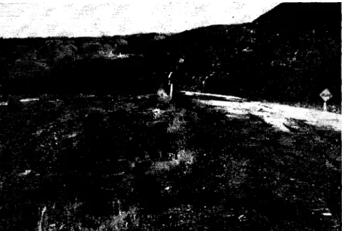
Fig. 7-Slide in highwav embankment at Pat's Creek, near Peace River, Alberta.
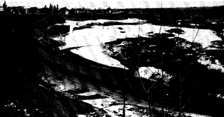
the average slope of the surface was about 3 to 1. The toe of the slide was in the creek bottom. Figure 8 shows the movement at the creek. It was completely blocked for a time and the bottom was heaved up as much as ten to fifteen feet.
Figure 9 is a view from the opposite side of the valley and shows the escarpment at the top of the slide about thirty feet above the road. This slide is the latest of three major movements which have occurred on this hillside during the past three years over a distance of about a mile. The first slide developed a few weeks after completion of the highway, the second the following year and the third a year later. The sequence of occurrence was down grade along the road. The aerial photographs as well as the appearance of the surface topography clearly indicate that these recent move-ments are in old slide areas. However it should be apprec-iated that the valleys in this area have all developed by the banks sliding. They differ only in the steepness of the slopes which have developed to-date.
Studies arc still under way in this area. However, exten-sive borings to depths of as much as 200 feet have shown comparatively thin beds of pre-consolidated soils ranging
6
available in the literature' 1 ' . There is evidence' that
the movement of such slides frequently is confined to com-paratively shallow depths, with sliding occurring on a plane approximately parallel to the surface of the slope. Henkel and Skempton- have suggested that the stability can be analyzed by assuming that the soil adjacent to the surface of shearing failure has reverted to a condition such that its cohesion is zero and its strength is dependent only on the effective pressure and its angle of internal friction as deter-mined from "slow" or "drained" triaxial compression tests. The slides in cases 4 and 5 possibly do involve movement to comparatively shallow depths. It is also possible that a stability analysis assuming no cohesion and shearing strengths consistent with an angle of internal friction from "slow" laboratory triaxial test-s would give results con-sistent with the field conditions.
However on theoretical grounds there is reason to believe that reduction in cohesion of the soil in the rebound process can only occur as a result of high seepage pressure in the zone of such reduction in cohesion. There is no evidence in the area under consideration that as a generality all slopes revert to a stability condition corresponding to zero cohesion
in the soil. Thus the most significant conclusion from a sta-bility computation made after a slide may be that seepage pressures have developed in the area of the movement. The approach does not permit a realistic assessment of the factor of safety against movement of existing slopes. In the area under consideration it would show very few slopes to be safe. From the practical point of view the crucial consideration in this area appears to be that unstable conditions develop coincident with the build up of subsoil seepage pressures. Case 6
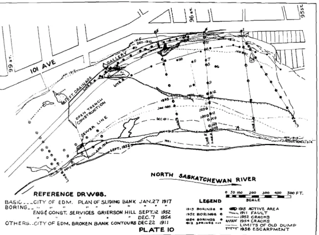
Figure 10 shows a plan of an unstable river bank area in the City of Edmonton for which records of movements are available dating back to 18H7. The vertical height from the river level to the top of the bank is 170 feet. In 1887 the average slope of the bank was about 2>1 :1.A major move-ment occurred in 1905. At this time the top of the bank moved back about 75 feet. This occurred at the end of a six year period of abnormally high precipitation. Between 1905 and 1915 the top of the bank moved back another 50 feet.
However it has been "table since that time except for a smal l area at the east end.
Tho movements of the toe of the slide have been much more startling. Between 1887 and 1893 the river encroached into the bank by about 50 feet. However since that time the river has been pushed out and it now is about 400 feet from it- ]8!);j position at the section of maximum movement. During the period ]U11 to 191ii the toe encroached on the river by about 100 feet. This coincided with a four year period of above average precipitation but about 1911 the policy was adopted of using the lower portion of the slope as a dump in an effort to stabilize the slope. This policy was continued for many years. Boring-, show as much as 50 feet of fill made up of loosely dumped soil from excavations, cinders, straw, manure, and garbage. The hillside is now on an average slope of about 5 to 1. Figure 11 shows two cross-section" through the 810pe with the logs of a number of test holes on these lines.
With the growth of the city a roadway out of the valley
Fig. 8-Soil movement at toe of slide in Pat's Creek, near Peace River, Alberta.
Fig. 9-Unstable area along Pat's Creek, seen from opposite of valley.
along the upper end of the slide area became an important traffic artery. For a number of years this road was main-tained on an embankment built along the face of the escarp-ment at the upper end of the slide. Periodic slides occurred in the embankment side slopes. These pushed up toes in the older sanitary fill further down the slope and this material continually creeps towards the river. The horizontal
move-ment due to creep in the fill material in recent years has averaged as much as 16 feet per annum.
In In.52 a comprehensive investigation was undertaken to determine the possibilities of stabilizing the road embank-ment so its surface could be paved. Present plans also contemplate a new arterial highway across the lower portion (Ifthr. slide if the area can be stabilized. Boring records
,)00
-
1-00_!
500 F T.. . 1915 ACTIVE. ARE A
u.l...'"1911 r:ALJL. T -'-.1952. CRACKS
lMAfI/ 195" CRACKS
- - LIMITS OF OLD DUMP
T"'"T""'T'"1956 E.SCARPME.NT
|Guセ
L..---'Il_-J
v' 191-'BORINGS • 1952, BORINQ8 II litH BORINGS • ",oa sp-.,wes •••fゥセN lO-Plan of Grierson Hill slide; City of Edmonton, Alberta. Fig. lL-Typical profiles of Grierson Hill slide; City of Edmonton, Alberta.
CROM-IKTlON UN'a.
gOlf-HUlON bINI S
...
were available from all investigation made in l\JUi and abo ill 19;iL.These along with the results of additional borings made in !\),i2 showed the natural subsoil deposits to be pre-consolidated beds of sand, silt, sandstone, a wide varietv of day shales and coal.
The recent sanitary fill deposits arc wet and soggy with free water showing in the lower portion of the fill. Generally the natural subsoil materials were hard and stable. However several coal seams showed free water with some artesian pressure,
The fundamental cause of the instability in this area appears to be seepage pressure originating in the various water bearing coal beds. The earlier movements plus the dumped fill over the lower portion of the area have resulted in the drainage being blocked from the coal seams with resultant build up of seepage pressure in the slumped and fill material. Both the 1911 and 1915 records showed springs in the area. None of these at present arc in evidence at the surface. However borings in these areas invariably show free water.
The 19,'i2 borings did not definitely define sufficient water that would warrant the installation of gravity drainage galleries. Therefore, in order to get additional information on the subsoil moisture conditions and also to provide a means for immediate stabilization of the road embankment. a series of twenty-nine closely spaced borings were put down along either side of the road. These were 16-inch diameter holes and varied in depth from 30 feet to 70 feet. Nineteen of the twenty-nine produced free water and these were pumped as wells intermittently or continuously as long as they produced water. All but three of the wells were pumped dry within a few days. Two of the remaining three have been pumped continuously at the rate of about 8,oo()
gallons per day since the summer of 19,i3. These two wells have yielded about 90% of the total volume pumped. From the summer of 1953 until December of 1955 over three million gallons of water were pumped from the wells.
The summer of 19.'i3 was the wettest in the Edmonton area since 1901. However despite the fact that the wells were not all functioning until late in the summer the
pump-iug prevented any major movement of the road embank-ment. The movement in the lower portion of the slope below
Iht' wells has not been completely arrested by the pumping but tho horizontal creep has bCPI1 at a rate less than half
of what it was previous to the pumping. The total area of the unstable area is about 2.') acres. It could therefore hardly be expected that the pumping of only two wells continuously would stabilize this whole area. However it has been sur-prisinglv effective in arresting movement over a major portion of the area.
The 1953 boring program also established a particular eoa I seam as being continuously water bearing over prac-tically the whole length of the roadway. This is at an
ele-vat.ion about JO()feet below the top of the bank and 70 feet above the river. This could be drained by a gravity drainage gallery hut it is a matter of comparing the economy of such an installation with that of pumping from wells.
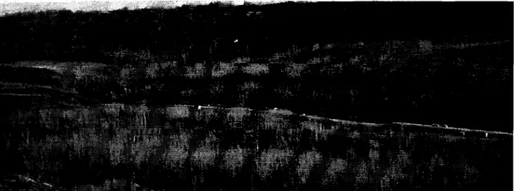
Figure 12 shows a general view of the area of this slide. Horizontally bored drains have been extensively used to stabilize slides by the State highway departments on the west coast. Such drains have been successfully used on some slides in Alberta but they have not been found satisfactory for extensive slides in pre-consolidated soils. The reasons for this are that in these deposits the water bearing strata mav be verv thin and horizontal holes several hundred feet long may be required to be effective. Under these circum-stances thc drilling cannot he controlled with sufficient accuracy to ensure that the hole will tap the water bearing zone.
Peterson' has pointed out the importance of rebound in the Bearpaw clay shales in the development of the valley slopes along the South Saskatchewan River. His work appears to indicate that seepage pressures are of minor importance as compared to rebound in these materials. He is dealing with much more highly plastic clay shales than have been encountered in general in the cases discussed above. There are records of movements of bridge piers and abutments in the general area of the location of "case 5" discussed above which ァゥhセ some indications of horizontal rebound without seepage pressures heing a factor. As more
data become available it may be possible more accurately to assess the relative importance of the two factors. It may well be that they will varv widelv between different types of clay shales.
Cases 1, 2, and 3show in spcr-ificeasps certain effectson engineering structures due to swelling or rebound of clay shales. In each of these cases the causes can be accurately determined. The availability of water is au essential factor. Seepage pressure and the potential seasonal and cyclical variations in such pressures are also extremely important factors. The conditions associated with the slides discussed in cases 4, 5, and' 6 are consistent with thcse same factors being of prime importance. However these cases illustrate the difficulty of accurately locating the zones and source of the seepage pressures. Case 6, in particular, however, shows the major effects possible in stabilization if the seepage pressures can be controlled.
Acknowledgments
The data presented in this paper come from several sources, including the Department of Highways of the Province of Alberta, the office of the senior highway engineer of the Northwest Highway System, the city engineer's
fi.""':.'''.'!i\NZセN
セ
department of the City qf Edillonton, the highway research project of the Research Council of Alberta, the rceords of Materials Testing Labora tories Ltrl., of Edmonton, student theses of the department of civil engineering of the l
'ni-versitv of Albertn., as well as the private records of the
author. The assistance from these sources is gratefullv
ucknowlcdgrxl. \[1'. H. nix of the Research Council セヲ Alberta assisted in the preparation of the sketches.
References
1 PETERSOX, R, (1956),. "Rebound in the Bearpuw Shale". Paper presented to the Engineering Geology Division of the Geological Society of America, Oct., ] 9.56.
2 TERZAGHI aJHI 1',;cK, "Soil Mechanics ill Engineering Prac-tice", p. 366. -
-3 SKE\\PTOK, A. \Y., (19-18),"The Rate of Sof'teniug in
swr
Fissured Clays with Sper-ial Reference to London Clay"Proc, 2nd I ni. COIlf. SoilMecti.,vol. 2, p. 50.
4 'l'ERZAUHI, K., (19361. "Stability ofSlopesof Xutural Clay".
T'roc.ls! I ni. Con]. Soil Merti.,vol. 1, p. 161.
sHENKEL,D ..T.,andSKE\lPTON,A. W., (1951)). "A Landslide at Juckfield, Shropshire, in a Heavily Over-Consolidated Clay". Ueoiechnique, vol. V., p, 131.