HAL Id: hal-02468541
https://hal.inria.fr/hal-02468541
Submitted on 5 Feb 2020
HAL is a multi-disciplinary open access
archive for the deposit and dissemination of
sci-entific research documents, whether they are
pub-lished or not. The documents may come from
teaching and research institutions in France or
abroad, or from public or private research centers.
L’archive ouverte pluridisciplinaire HAL, est
destinée au dépôt et à la diffusion de documents
scientifiques de niveau recherche, publiés ou non,
émanant des établissements d’enseignement et de
recherche français ou étrangers, des laboratoires
publics ou privés.
A Sensor-Based Approach for Dependable Physical
Interaction
Angel del Pobil, Mario Prats, Philippe Martinet, Sukhan Lee, Rüdiger
Dillmann
To cite this version:
Angel del Pobil, Mario Prats, Philippe Martinet, Sukhan Lee, Rüdiger Dillmann. A Sensor-Based
Approach for Dependable Physical Interaction. ICRA08 - 6th Workshop on ”Technical Challenges for
Dependable Robots in Human Environments”, May 2008, Pasadena, United States. �hal-02468541�
A Sensor-Based Approach for Dependable Physical Interaction
Angel P. del Pobil
1, Mario Prats
1, Philippe Martinet
2, Sukhan Lee
3, R¨udiger Dillmann
4 1Universitat Jaume I, Spain
2
LASMEA, Universit´e Blaise Pascal, France
3ISRC, Sungkyunkwan University, South Korea
4
Universit¨at Karlsruhe, Germany
Abstract— Robotic manipulation of everyday objects and
dependable execution of household chores is one of the most desired and challenging skills for future service robots. Most of the current research in robotic grasping is limited to pick-and-place tasks, without paying attention to the whole range of different tasks needed in human environments, such as opening doors, interacting with furniture, household electrical appli-ances, etc. In this article, a sensor-based integrated framework for specifying both the grasp and the task is presented, with the goal of motivating dependable task-oriented grasping and manipulation. The grasp is defined as a desired task-suitable relationship between the robot hand and the object being manipulated. The task is defined under the task frame formalism [1], which allows to specify tasks for sensor-guided dependable interaction. Some guidelines for sensor-based execution of tasks defined under the proposed formalism are also given. Three different examples of dependable manipulation tasks, performed by three different robots, are presented, making use of the proposed approach and disparate sensor information: book grasping by tactile-force integration, door opening by vision-force control, and force-guided humanoid interaction with kitchen furniture.
I. INTRODUCTION
Autonomous robots need advanced manipulation skills in order to be useful for the end-user [2]. Most of current research in robotic manipulation is limited to pick and place tasks, without paying attention to the whole range of different tasks needed in human environments. Apart from grasping objects for pick and place, a dependable service robot work-ing in cooperation with humans needs a complete repertoire of tasks, including opening doors, interacting with furniture and household electrical appliances, switching on/off the lights, etc.
Most of the research in robotic grasping community aims at finding a set of contacts on the object in order to obtain force-closure grasps [3]. Force-closure guarantees that the grasp can compensate forces in any direction, but is a too restrictive condition in the sense that it would be much more natural to plan a grasp which can generate the force required for the task, instead of all the possible forces. It is worth noting that there are very few approaches on task-oriented robotic grasping in the community [4], [5]. In the same way that robotic grasping works usually do not take the task into account, task planning works for robotic compliant interaction rarely consider the grasp planning problem. The grasp depends completely on the intended task, and vice versa. At the same time that the task dictates the way the
hand must be arranged around an object, also the grasp dictates the actions that can be safely performed with it.
We propose a common framework where the grasp and the task are closely related, allowing both task and grasp spec-ification and dependable sensor-guided execution in terms of hand, grasp and task frames. The grasp is defined as a desired task-suitable relationship between the robot hand and the object being manipulated, whereas the task is defined under the task frame formalism [1], as a desired motion that must be applied to the object. The concept of grasp
frame is used for relating the grasp with the task into a
common framework. On the one hand, the grasp frame is used as the goal for hand control. On the other hand, it is related to the task, through the object structural model. The grasp frame allows to transform the desired task motion, given in object coordinates, to robot motion, given in robot coordinates, as long as a suitable sensor-based estimation of the hand-to-object relative pose is provided, allowing to deal with modelling errors, grasp uncertainties, sliding, etc. in a dependable way. Having a good estimation of the hand-to-object pose, the task frame can be estimated in robot coordinates during execution, following a sensor-based task frame tracking approach [1], allowing the robot to adapt its motion to the particular object mechanism, even if no detailed model is present. Several examples of dependable sensor-guided compliant physical interaction tasks, based on the proposed framework, are presented, showing the suitability of our approach for the fast implementation of dependable interaction tasks under very different robotic systems.
II. AFRAMEWORK FOR DEPENDABLE PHYSICAL INTERACTION
A. Task-oriented grasp
We make use of three different frames for dependable task-oriented grasping: the task frame, the hand frame and the
grasp frame (see Figure 1).
The task frame (T ) is a frame given in object coordinates, thus linked to the object frame (O), where the task is specified according to the task frame formalism [1]. The pro-grammer has to choose a suitable task frame, where the axis match the natural constraints imposed by the environment (by the mechanism in our case).
The hand frame (H) is a frame attached to the robot hand (or tool) and it is used for control. Therefore, it is necessary
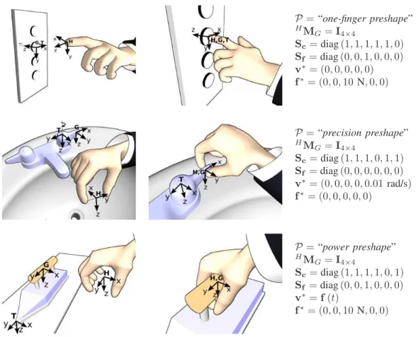
P = “one-finger preshape” HM G= I4×4 Sc= diag (1, 1, 1, 1, 1, 0) Sf = diag (0, 0, 1, 0, 0, 0) v∗= (0, 0, 0, 0, 0) f∗ = (0, 0, 10 N, 0, 0) P = “precision preshape” HM G= I4×4 Sc= diag (1, 1, 1, 0, 1, 1) Sf = diag (0, 0, 0, 0, 0, 0) v∗= (0, 0, 0, 0, 0.01 rad/s) f∗ = (0, 0, 0, 0, 0) P = “power preshape” HM G= I4×4 Sc= diag (1, 1, 1, 1, 0, 1) Sf = diag (0, 0, 1, 0, 0, 0) v∗= f (t) f∗ = (0, 0, 10 N, 0, 0)
Fig. 1. Some task examples supported by the task-oriented grasping framework. First: pushing a button, with a force reference. Second: turning on a tap, with a velocity reference. Third: ironing task, with a velocity and force reference. T , H and G are, respectively, the task, hand and grasp frame.
to link it with the robot end-effector frame (E), normally through robot hand kinematics.
The grasp frame (G) is a frame given in object coordinates, and related to the task frame through object kinematics. This frame is set to parts of the object which are suitable for grasping and task execution.
The task-oriented grasp is then defined as a desired relative pose (possibly under-constrained) between the hand frame and the grasp frame. If this desired relative pose is achieved, the task, defined in the task frame, can be transformed to the hand frame, through the grasp frame, allowing the robot to make the motion needed for the task. Constrained and free degrees of freedom for the grasp are indicated. For the constrained DOFs, the hand frame must completely reach the desired relative pose with respect to the grasp frame. However, for free degrees of freedom, there is no particular relative pose used as reference. Instead, the robot may select a suitable pose, according to manipulability, joint limit avoidance, etc.
Let T , G, H and E be the task, grasp, hand and end-effector frames respectively. EM
H, GMT and HMG are
homogeneous matrices relating end-effector frame to hand frame, grasp frame to task frame and hand frame to grasp frame respectively, being iM
j = £i Rj itj ¤ , whereiR j is
the 3 × 3 rotation matrix between frames i and j, and it j
represents the position of frame j with respect to frame i.
Let P = {m0, m1, . . . , mn} be the hand posture, mi being
the angle for each of the n motors of the hand. A task-oriented grasp is defined as:
G =©P, H, G,HMG, Sc
ª
(1) where Sc is a 6 × 6 diagonal selection matrix which
indi-cates the controlled degrees of freedom for the task-oriented grasp. The task is defined as a velocity/force reference in the task frame:
T = {T, v∗, f∗, Sf} (2)
where Sf is a 6 × 6 diagonal selection matrix, where
a value of 1 at the diagonal element i indicates that the corresponding DOF is controlled with a force reference, whereas a value of 0 indicates it is controlled with a velocity reference. A velocity reference is suitable for tasks where a desired motion is expected, whereas a force reference is preferred for dynamic interaction with the environment, where no object motion is expected, but a force must be applied (for polishing a surface, for example). v∗ and f∗
are, respectively, the velocity and force reference vectors. A suitable force controller must convert the force references on force-controlled DOFs to velocities, so that the task is finally described as a desired velocity given in the task frame: τ∗
For task execution, the desired velocity τ∗
T is converted from
the task frame, to the robot end-effector frame as:
τE=EWH· dHWG·GWT· τT∗ (3)
where iW
j is the 6 × 6 screw transformation matrix
associated to iM j.
B. Sensor-guided physical interaction
Whereas EM
H andGMT can be computed from robot
kinematics and object model respectively, dHM
G (the
esti-mated relative pose between the robot hand and the part of the object being manipulated) depends on the particular ex-ecution and should be estimated online by the robot sensors. The error between the desired relative pose,HM
G, and the
estimated pose, dHMG, can be due to the particular object
mechanism, or due to task redundancy, where a particular DOF is controlled by a secondary task. The robot must always estimate the hand-to-task relationship during task execution by means of the model, world knowledge, vision sensors, tactile sensors, force feedback, etc. The estimation of dHMG is the key for computing the task frame in robot
coordinates, thus allowing the transformation of the task specification into dependable robot motion.
The best sensor to estimate this relationship is vision. A robot could be observing its hand and the object si-multaneously, while applying model-based pose estimation techniques. Another interesting sensor is a tactile array, which provides detailed local information about contact, and could be used to detect grasp mistakes or misalignments. In any case, as the robot is in contact with the environment, it is extremely important to design a controller that can deal with unpredicted forces and adapt the hand motion accordingly. In general, the best solution is to combine several sensor modalities for getting a robust estimation.
III. APPLICATION OF THE FRAMEWORK
The proposed framework has been applied to three differ-ent robotic systems: the UJI Service robot [6] at the Robotic Intelligence Lab in Castell´on (Spain), a mobile manipulator [7] during a short stay at the Intelligent Systems Research Center in Sungkyunkwan University (South Korea), and the Armar-III Humanoid Robot [8], also during a short stay in Karlsruhe University (Germany). The tasks involved:
• Book grasping by means of tactile and force integration. • Door opening by vision and force feedback.
• Humanoid physical interaction with several kitchen
fur-niture (drawers, dishwasher, etc.) by force control with joint and task redundancy management.
The variety of the tasks that have been implemented shows the versatility of the proposed framework, and its suitability for the fast implementation of dependable physical interaction tasks in very different robotic systems. All the tasks have been described in such a way that no object models are necessary for successful execution. Instead, the robot is able to adapt its motion to the particular case, without being specifically programmed for any particular task.
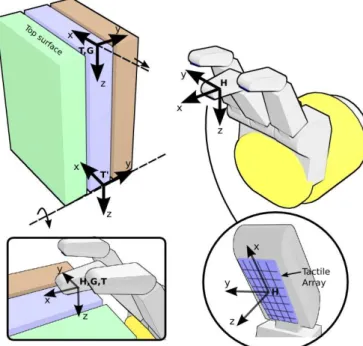
Fig. 2. Frames involved in the book grasping task. The tactile array is used to estimate the relationship between the hand and the grasp frame,HM
G.
A. Experiment I: book grasping by tactile-force combination
For the first experiment, the sensor-based compliant phys-ical interaction framework is applied to the task of taking out a book from a bookshelf, using the UJI Service Robot. The goal of the task is to extract a book from a shelf, while standing among other books. The approach is to do it as humans do: only one of the fingers is used, which is placed on the top corner of the target book and is used to make contact and pull back the book, making it turn with respect to the base, as shown in Figure 3. In this task, the force/torque sensor is used to apply a force towards the book and avoid sliding, whereas a tactile array provides detailed information about the contact, and helps estimating the hand and grasp frame relationship. As shown in Figure 2, there is one tactile array on each of the fingertips. This sensor consists of an array of 8 × 5 cells, each of one can measure the local pressure at that point.
1) Planning the task, hand and grasp frame: In Figure
2, a representation of the book grasping task, including the necessary frames, is shown. There are two possibilities for the task frame in this case. The first is to set it to the book base (frame T0 in Figure 2), so that the task is described as
a rotation velocity around this frame. The second possibility is to set the task frame on the top edge of the book (frame
T in Figure 2), so that the task is described as a negative
translational velocity along X direction. We have opted for the second solution, because, in this case, the task frame coincides with the grasp frame, and, then, there is no need to know the book model. In the first case, the height of the book should be known in order to transform the task velocity from the task frame to the hand frame. By adopting the second solution, we make the approach general for any
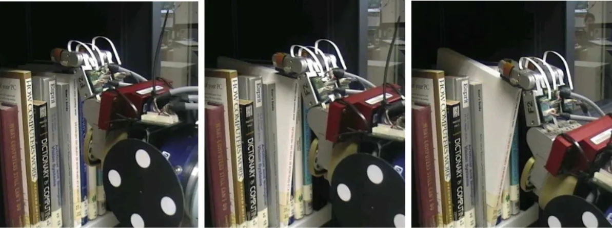
Fig. 3. The robot grasping the book by means of force and tactile-based continuous estimation of hand-to-object relative pose.
book size. Two references are set in the task frame, v∗ and
f∗. The first one is set to a negative velocity in X axis, in
order to perform the task motion, whereas f∗is set to a force
along Z axis. This force is needed in order to make enough pressure on the book surface and avoid slip. We have set it to 10 N for our particular system, but it depends on the friction coefficient between the fingertip and the book. For small friction, a bigger force would be needed. Therefore, Sf is set to diag(0, 0, 1, 0, 0, 0).
For this task, we define a special hand posture where one of the fingers is slightly more closed than the other ones, so that we can easily make contact on the top of the book with one finger, as shown in Figure 2. The hand frame is set to the inner part of the middle finger fingertip, just in the centre of the tactile sensor. The hand frame pose with respect to the robot end-effector, EM
H, is computed from
hand kinematics.
The fingertip has to make contact on the top of the book. Therefore, we set the grasp frame to the book top surface, which could be located by vision or range sensors. The desired relationship between the hand and the grasp frame,
HM
G, is set to the identity.
2) Estimating hand-book relative pose: In this case, the
task is performed by combining force and tactile feedback. Tactile information is used to estimate and improve the contact between the hand and the book, whereas force feedback is used in order to cope with uncertainties and ensure that a suitable force is performed on the book surface so that there is no sliding.
Contact on the book is performed with the tactile array. Depending on the sensor cells that are activated, the rel-ative pose between the sensor surface and the book can be estimated. It is not possible to compute the complete relative pose only with tactile sensors, because they only provide local information when there is contact. However, we can obtain a qualitative description of the relative pose. For example, if there is contact with the upper part of the sensor, but not with the lower part, we can deduce that the sensor plane is rotated around Y axis with respect to the book top plane.
All the tactile cells lie in the XY plane of the hand frame.
We consider that the finger is completely aligned with the book surface when there are cells activated on each of the four XY quadrants of the hand frame, i.e., all the tactile sensor surface is in contact. If there is contact on the upper half of the sensor, but not on the lower half, or vice versa, we consider that there is a rotation about Y axis, between the sensor (hand frame) and the book surface (grasp frame). Similarly, a rotation around X axis can be detected.
3) Improving the grasp: The goal of this process is to
align the finger (tactile sensor) surface with the book surface, taking as input the qualitative description of the relative pose, described in the previous point. We follow a reactive approach, where fingertip rotation around X and Y axis of the hand frame is continuously controlled, in order to obtain contact on each of the XY quadrants of the hand frame. With this approach, the behaviour of the robot is completely reactive to the tactile sensor readings. The goal is to keep the sensor plane always parallel to the book top plane, thus ensuring that dHMG= I4×4.
4) Task motion and coping with uncertainties: According
to the task description, the task motion is performed by moving the hand along negative X axis of the task frame, while applying a force along Z axis. This motion makes the book turn with respect to the base, as shown in Figure 3. Note that, as the fingertip moves backwards and the book turns, the tactile sensor may lose contact with the lower part. This situation is detected by the qualitative pose estimator, and corrected with the control strategy described in the previous point, so that the hand frame is always aligned with the grasp frame, ensuring that task motion can successfully be transformed to dependable end-effector motion by equation 3. Figure 3 shows a sequence of the robot performing the task.
B. Experiment II: door opening by vision-force combination
In this section, the framework for sensor-based compliant physical interaction is applied to the task of pulling open the door of a wardrobe, using a mobile manipulator composed of an Amtec 7DOF ultra light weight robot arm mounted on an ActivMedia PowerBot mobile robot. The hand of the robot is a PowerCube parallel jaw gripper. This robot
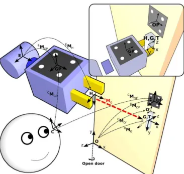
Fig. 4. The vision task is to align hand frame H with the grasp frame G.
belongs to the Intelligent Systems Research Center (ISRC, Sungkyunkwan University, South Korea), and is already endowed with recognition and navigation capabilities [7], so that it is able to recognise the object to manipulate and to retrieve its structural model from a database.
1) Planning the task, hand and grasp frame: The
struc-tural model of the door is shown in Figure 4. The task of pulling open the door can be specified naturally as a rotation around Y axis of frame O, but also as a negative translation velocity along Z axis of the frame G. The second alternative has the advantage that we can setGM
T = I4×4,
without the need to know the door model. We adopt this approach in order to make the solution valid for other doors. Thus, T = G, and we set v∗ to be a negative translation
velocity along Z axis (the desired opening velocity). As there is no need for force references for this task, f∗ = 0 and
Sf = 06×6.
For the parallel jaw gripper, there are very few manip-ulation possibilities. We consider only one possible task-oriented hand preshape, which is the precision preshape. The hand frame is set to the middle point between both fingertips, as shown in Figure 4.
As the door contains a handle, the grasp frame is set to the handle, so that the grasp is performed on it. More concretely, the grasp frame is set centered at the handle major axis, as shown in Figure 4. Then, according to the specification of the hand and grasp frames, the desired relationship between both is HM
G = I4×4, i.e. the identity: when grasping, the hand
frame must be completely aligned with the grasp frame (the handle must lie in the middle point between both fingertips).
2) Estimating hand-handle relative pose: As already
ex-plained in the previous sections, the relationship between the hand and the handle must be estimated continuously during task execution, in order to be able to transform the task
Fig. 5. The mobile manipulator at ISRC opening a door by means of force and vision combination
motion (given in the task frame) to dependable robot motion (given in the end-effector).
Virtual visual servoing [9] is used to estimate the pose of the hand and the handle, using a set of point features drawn on a pattern whose model and position is known. One pattern is attached to the gripper, in a known position
EM
GP. Another pattern is attached to the object, also in a
known position with respect to the object reference frame:
OM
OP. As future research we would like to implement a
feature extraction algorithm in order to use natural features of the object instead of the markers [10]. Figure 4 shows the different frames involved in the relative pose estimation process and the task.
The matrix HdMG, which relates hand and handle, is
computed directly from the pose estimation of the gripper and the object, according to the following expression:
¡C MGP ·EM−1GP ·EMH ¢−1 ·CM OP·OM−1OP·OMG (4) where CM
GP is an estimation of the pose of gripper
pattern, expressed in the camera frame, and CM
OP is an
estimation of the object pattern pose, also in the camera frame. EM
H and OMG are the hand and grasp frame
positions with respect to the end-effector and the object reference frame respectively, as set in the previous points.
3) Improving the grasp: After pose estimation, a measure
of the error between the desired (HM
G) and current ( dHMG)
hand-grasp relative pose is obtained. It is desirable to design a control strategy so that the grasp is continuously improving
during task execution. With a vision-based approach, any misalignment between the gripper and the handle (due to sliding, model errors, etc.) can be detected and corrected through a position-based visual servoing control law [11]. We set the vector s of visual features to be s = (t uθ)T, where t is the translational part of the homogeneous matrix dHMG,
and uθ is the axis/angle representation of the rotational part of dHM
G. The velocity in the hand frame τH is computed
using a classical visual servoing control law:
τH= −λe +
c
∂e
∂t (5)
where e(s, sd) = cL+
s(s − sd) (in our case, sd = 0, as HM
G = I4×4). The interaction matrix cLs is set for the
particular case of position-based visual servoing: c Ls= µ −I3×3 03×3 03×3 −Lw ¶ Lw= I3×3−θ 2[u]×+ Ã 1 − sinc(θ) sinc2(θ 2) ! [u]2×
where [u]× is the skew anti-symmetric matrix for the
rotation axis u. Finally, the end-effector motion is computed as τE=EWH· τH.
4) Task motion and coping with uncertainties: The
end-effector velocity that the robot has to achieve in order to perform the task motion, is computed by transforming the task velocity, from the task frame to the end-effector frame, according to equation 3.
Even if the relative pose between the hand and the handle, dHM
G, is estimated and corrected continuously, this
estimation can be subject to important errors, considering that it is based on vision algorithms, that can be strongly affected by illumination, camera calibration errors, etc. Due to this fact, the robot motion is also subject to errors, and cannot match exactly the desired motion for the task. As the hand is in contact with the environment, any deviation of the hand motion regarding the task trajectory will generate important forces on the robot hand that must be taken into account.
We adopt an external vision/force control law [12] for integrating vision and force and coping with uncertainties. With this approach, the force vector, with current external forces, is used to create a new vision reference according to:
s∗= sd+ cL
s· dL−1× · K−1(f∗− f ) (6)
where f∗is the desired wrench, added as input to the
con-trol loop (null in this particular case), K is the environment stiffness matrix, and s∗ is the modified reference for visual
features. cL× relates τE and ˙XE according to ˙XE= cL×· τE
[11]. Then, the visual servoing control law, described in the previous point, takes as visual reference the new computed reference, s∗.
In conclusion, there are two simultaneous end-effector motions: one, computed by equation 3, which is in charge
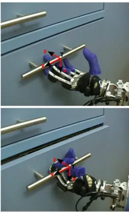
Fig. 6. The task frame is set to the handle. The task is specified as a velocity reference along negative Z axis. A power grasp is performed.
of performing dependable task motion, and another one, computed by equation 5, in charge of continuously aligning the hand with the handle by vision-force control. For more experimental results of the vision/force-guided door opening task, along with a detailed analysis and a demonstration video, please refer to [13].
C. Experiment III: humanoid physical interaction with kitchen furniture
For this experiment, we focus on tasks that involve force-guided robust physical interaction of a humanoid robot with articulated furniture found in the kitchen, such as opening doors and drawers. The Armar-III humanoid robot, built up by the Collaborative Research Center 588 in Karlsruhe, has been used for these experiments [8]. This robot is composed of a humanoid torso mounted on a holonomic mobile plat-form, and has a total of 43 DOFs. A complete kitchen has been built in order to validate the robot capabilities in a realistic household environment. The kitchen contains all of the elements that can be found in any common kitchen, like a dishwasher, a fridge, a microwave, different cupboards, drawers, etc.
1) Planning the task, hand and grasp frame: We consider
the task of pulling open the different doors and drawers found in a kitchen environment. The task and grasp frames are always set to the handle, as shown in Figure 6, and the task velocity is set to a negative value along Z axis, i.e. v∗ = (0, 0, −20, 0, 0, 0)T mm/s. This avoids the use of the
same task description for the different doors and drawers, independently of the particular size or hinge position. The force reference is not required for this particular task, thus Sf = 0.
As shown in Figure 6, the hand is set to a power grasp configuration, where the thumb is opposed to the rest of fingers, and the hand frame is set to the center of the grasp. Task redundancy is allowed in the rotational DOFs: Sc= diag(1, 1, 1, 0, 0, 0). Normally, only a rotation around
the handle axis should be allowed as a task redundant DOF. However, as the robot’s hand is highly compliant, and all the DOFs are force-controlled, the three cartesian rotational DOFs are set to be controlled by the secondary task (avoiding joint limits), and not by the main task.
2) Estimating hand-handle relative pose: Due to the task
redundancy, the relative rotation between the hand and the handle is not fixed. It can vary during execution according to the cost function minimization approach (see examples of Figure 7). However, this hand-to-handle relative pose, dHMG,
must be known in order to compute the task jacobian and transform the task velocity into robot joint velocity.
The framework outlined in section II assumes that dHM G
can be computed through robot sensors. Here, position-force information is used in order to find always the motion direc-tion which minimizes the external forces. The robot starts by pulling the handle. The mechanism of the particular door, as well as the error in the estimation of dHM
G, generates small
forces in the hand, which the robot tries to minimize by updating its position following an impedance force control approach (introduced in point III-C.4). The robot keeps a history of the hand trajectory and aligns the task and grasp frame with the vector tangent to this trajectory, thus updating the hand-to-handle relative pose estimation, dHM
G. With this
approach, the robot autonomously adapts to the particular door, without having any model, and even without knowing the particular mechanism.
3) Improving the grasp: The humanoid robot makes use
of two different kinds of redundancy for continuously adopt-ing a confortable grasp duradopt-ing task execution: task and joint redundancy. In the context of this experiment, 8 DOF are used in the Armar-III humanoid robot: 7 in the arm, and 1 in the hip (yaw). Therefore, two redundant degrees of freedom exist at the joint level, allowing the robot to reach a given cartesian pose with many different joint configurations.
We adopt the well-known gradient projection method (GPM) for joint redundancy management [14]. The general approach is to project a secondary task into the nullspace of the first task, as following:
˙q = J+EτE+ (I − J+EJE)ej (7)
where ˙q is a vector with joint velocities, τE is the desired
end-effector cartesian velocity, JEis the arm jacobian at the
end-effector, (I − J+EJE) is the nullspace projector, and ej
is the secondary task, which is normally computed as the gradient of a cost function h(q), i.e. ej = ∂h∂q. There are
many different possibilities for the cost function: increase
manipulability, minimize energy consumption, etc. In our case, we compute h in order to avoid joint limits, thus keeping a natural arm posture. Concretely, ej is taken as:
eji= ∂h ∂qi = −qi−qui qr i if qi> q u i −qi−qil qr i if qi < q l i 0 in other case where qu
i, qil and qri are, respectively, the upper bound,
lower bound and range for joint i. By upper and lower bound, we understand the joint value at which the joint limit avoidance secondary task is activated (not the mechanical limit).
For dealing with task redundancy, equation 7 must be transformed to task coordinates, by means of the end-effector-to-task estimation, dEMT =EM
H · dHMG·GMT.
First, the task jacobian must be computed from the arm jacobian, as:
JT = dEWT −1
· JE (8)
A modified task jacobian is then computed, taking into account task redundancy, as Jr
T = Sc· JT, being Sc the
diagonal selection matrix, introduced in section II, which selects the degrees of freedom of the task frame necessary for the main task. Then, equation 7 is transformed into:
˙q = Jr
T+τT∗+ (I − JrT+JrT)ej (9)
With this new expression, ej is projected not only on the
joint redundant DOFs, but also on the task redundant ones. Therefore, more DOFs are available for the secondary task, allowing the robot to perform the main task, while effectively performing auxiliary motion.
4) Task motion and coping with uncertainties: If the
estimation of the task frame with respect to the end-effector, d
EMT, was perfect, the robot could perform the task without
any kind of force feedback. However, in practice, the task frame estimation contains many errors. As the robot is in contact with the environment, an error in the trajectory generates very big forces on the robot hand. Thus, it is necessary to control the force so that no big forces appear on the robot hand. The robot, then, executes the task by trusting on its estimation of the task frame, but locally modifies the trajectory, following an impedance approach, in order to avoid excessive forces.
The force control law running in the robot for compliant cartesian velocity control with joint and task redundancy is the following:
˙q = Jr
T+τT∗+(I−JrT+JrT)ej+J+TK−1( dTWF·f −f∗) (10)
being K the stiffness matrix for force control [15], dTWF
the screw transformation matrix associated to the homoge-neous matrix dTM
F, which relates the force sensor frame
and the task frame. The matrix dTMF can be computed as
d
TM
F = dEMT −1
·EM
Fig. 7. The Armar-III robot interacting with the kitchen furniture: fridge, drawers, dishwasher and cupboards
sensor frame with the end-effector. Finally, f is the measured force at the force sensor frame, and f∗ the desired force at
the task frame.
Whereas the first two terms allow to perform the task motion and the auxiliary task, the last term adds a correction to the joint velocities depending on desired and current forces, allowing for a dependable execution of the task, even when important errors exist in the task frame estimation,
d
EM
T (and, thus, in J+T).
Figure 7 shows the Armar-III humanoid robot interacting with four different elements found in a common kitchen: a fridge, a drawer, a dishwasher and a cupboard. Each of them have different size and even different mechanism. In the case of the dishwasher, the hinges are located at the bottom part, unlike the fridge and cupboard where the hinges are at left.
In the case of the drawer, the mechanism is not a rotation, but a translation. However, the task description is the same for all of them: pulling the handle. By the on-line force-based estimation of the hand-to-handle relative pose, the robot is able to adapt its motion to the particular case, without being specifically programmed for any particular task.
In addition, because of the high number of redundant DOFs and the task and joint redundancy management, the humanoid robot is able to perform the tasks in a very natural way, by adopting a comfortable arm posture, far from the joint limits, if possible. Figure 8 shows the effects of the secondary task when opening the door of the dishwasher. When the task starts, cost is decreased due to internal motion, using the redundant DOFs, to a value close to zero. The cost remains small during task execution, until the end, when it
Fig. 8. Effects of the secondary task. Top: cost for each joint. Down: norm of the cost vector.
starts increasing. This point corresponds to the case when the arm is almost completely stretched (see Figure 7, third row, third column, and joint 5 cost in Figure 8 top). At this point, the task is considered as finished, as very little internal motion is possible, making it impossible to avoid the joint limits.
IV. CONCLUSIONS
We have shown three different examples of robotic execu-tion of everyday chores, built on top of a general framework for specifying dependable compliant physical interaction tasks based on multisensor information. First, the framework has been applied to a book grasping task, combining tactile and force feedback. The second application has been a door opening task with a mobile manipulator endowed with a parallel jaw gripper, using vision and force sensors. Finally, a third example has shown the use of a complex humanoid robot for performing everyday tasks in a kitchen environ-ment. The three examples exhibit a considerable degree of robustness, in the sense that the use of multiple sensor feedback on all of them allows to deal with uncertainties and errors, so that the robot can adapt its motion depending on the particular situation, without being specifically pro-grammed for a particular task. The implementation of these examples in very different robotic systems during a short period of time shows the suitability of the framework for versatile specification and fast implementation of disparate
multisensor physical interaction tasks.
As future research, we would like to use the proposed framework for the specification and compliant execution of several common tasks in home environments, based on inte-grated visual, tactile and force feedback. We think that the integration of multiple and disparate sensor information for hand-to-object pose estimation is a key point for successful and dependable robotic physical interaction.
REFERENCES
[1] H. Bruyninckx and J. De Schutter. Specification of force-controlled actions in the ’task frame formalism’: A synthesis. IEEE Transactions
on Robotics and Automation, 12(5):581–589, 1996. ISSN: 1042-296X.
[2] C.C. Kemp, A. Edsinger, and E. Torres-Jara. Challenges for robot manipulation in human environments. IEEE Robotics & Automation
Magazine, 14:20–29, 2007.
[3] A. Bicchi and V. Kumar. Robotic grasping and contact: A review. In
Proc. IEEE Int. Conf. on Robotics and Automation, pages 348–353,
San Francisco, CA, 2000.
[4] Z. Li and S. Sastry. Task oriented optimal grasping by multifingered robot hands. In ICRA, pages 389–394 vol.4, 1987.
[5] Ch. Borst, M. Fischer, and G. Hirzinger. Grasp Planning: How to Choose a Suitable Task Wrench Space. pages 319–325, New Orleans, LA, USA, April 2004.
[6] M. Prats et al. Towards multipurpose autonomous manipulation with the uji service robot. ROBOTICA, (25):245–256, 2007.
[7] S. Lee, S. Lee, J. Lee, D. Moon, E. Kim, and J. Seo. Robust recognition and pose estimation of 3d objects based on evidence fusion in a sequence of images. In Proc. of IEEE International Conference
on Robotics and Automation, Rome, Italy, April 2007.
[8] T. Asfour, K. Regenstein, P. Azad, J. Schroder, A. Bierbaum, N. Vahrenkamp, and R. Dillmann. Armar-iii: An integrated humanoid platform for sensory-motor control. 6th IEEE-RAS International Conference on Humanoid Robots, pages 169–175, 4-6 Dec. 2006.
[9] E. Marchand and F. Chaumette. Virtual visual servoing: a framework for real-time augmented reality. In EUROGRAPHICS 2002, volume 21(3), pages 289–298, Saarebr¨ucken, Germany, September 2002.
[10] A. Comport, E. Marchand, and F. Chaumette. Complex articulated object tracking. Electronic Letters on Computer Vision and Image
Analysis, 5(3):21–31, 2005.
[11] P. Martinet and J. Gallice. Position based visual servoing using a nonlinear approach. In IEEE/RSJ International Conference on
Intelligent Robots and Systems, volume 1, pages 531–536, Kyongju,
Korea, October 1999.
[12] Y. Mezouar, M. Prats, and P. Martinet. External hybrid vision/force control. In Intl. Conference on Advanced Robotics (ICAR’07), Jeju, Korea, 2007.
[13] M. Prats, P. Martinet, A.P. del Pobil, and S. Lee. Vision/force control in task-oriented grasping and manipulation. In
IEEE/RSJ Int. Conf. on Intelligent Robots and Systems, San
Diego, USA, 2007. Video available in proceedings or at: http://www.robot.uji.es/lab/plone/Members/mprats/ video/edited/iros07-video.wmv.
[14] Bruno Siciliano. Kinematic control of redundant robot manipulators: A tutorial. Journal of Intelligent and Robotic Systems, 3(3):201–212, 1990.
[15] W. Khalil and E. Dombre. Modeling identification and control of