ChromoUpdate: Optimization Technique for
Controlling Color-Changing Materials
by
Cattalyya Nuengsigkapian
S.B., E.E.C.S, Massachusetts Institute of Technology (2019),
Computer Science and Engineering
Submitted to the
Department of Electrical Engineering and Computer Science
in Partial Fulfillment of the Requirements for the Degree of
Master of Engineering in Electrical Engineering and Computer Science
at the
Massachusetts Institute of Technology
May 2020
© Massachusetts Institute of Technology 2020. All rights reserved.
Author:
_____________________________________________________________
Department of Electrical Engineering and Computer Science
May 19, 2020
Certified by: _____________________________________________________________
Stefanie Mueller
Assistant Professor of Electrical Engineering and Computer Science
Thesis Supervisor
Accepted by: _____________________________________________________________
Katrina LaCurts, Chair, Master of Engineering Thesis Committee
ChromoUpdate: Optimization Technique for
Controlling Color-Changing Materials
By
Cattalyya Nuengsigkapian
Submitted to the Department of Electrical Engineering and Computer Science
on May 19, 2020 in Partial Fulfillment of the Requirements for
the Degree of Master of
Engineering in Electrical Engineering and Computer Science
ABSTRACT
Previous research re-programs the color texture of photochromic-coated objects by saturating the
whole surface to black with UV LED before attempting to get a multi-color surface. Thus, it is
not possible to directly transform the current color to the target color without resetting to black
first. Moreover, partial update to the texture involves recoloring the entire surface.
In this project ChromoUpdate, we introduce color texture updating to update from a color to
another color directly by using a UV projector to give us ability to control activation pixel-wisely
and implement a program to support local update.
ChromoUpdate substantially speeds up the design iteration, by decreasing the projection time by
twice in average and allow users to re-design and re-apply their pattern iteratively.
Thesis Supervisor: Stefanie Mueller
A C K N O W L E D G E M E N T S
I would like to sincerely thank my thesis supervisor, Professor Ste-fanie Mueller, for her meaningful advice and incredible support of more than a year. Thank you for teaching me how to do research, pre-sentations, and document sources well. You have helped me become a better researcher in every way and truly impacted my academic and personal growth.
I would also like to thank my academic advisor, Professor Barbara Liskov, for her invaluable counsel over the past five years. Thank you for guiding me towards academic success here at MIT.
I would also like to extend a huge thank you to my research su-pervisor, Michael Wessley, for his essential knowledge on conducting scientific research at the level of conference paper submission quality. Thank you for showing me how to effectively collaborate in a team setting and guiding me as I worked on my thesis. Also, thank you for your assistance with experiments to improve this project and all your work in Photo-Chromeleon that allowed us to extend and complete this project.
I want to thank Alexey Kashapov for his great work in Camera system and Blender that made this project possible with very good alignment from two projectors. Thank you for being an irreplaceable teammate who is willing to help with anything.
Moreover, thanks to everyone in the HCIE lab for making the lab a wonderful place to work. I enjoy every moment working in this lab. Thank you to all my friends who make MIT a special place that is full of memories. Thank you to my family for always supporting me unconditionally, encouraging me to overcome obstacles, and con-tributing to all my success.
Lastly, thank you to MIT for an unforgettable five years; I have learned and grown a lot since my first day on campus. I cherish the opportunities I have received here, and the MIT community has in-spired me. Thank you for bringing out the best of me.
C O N T E N T S
1 introduction 1
1.1 Motivation . . . 1
1.2 Summary of Key Contributions . . . 2
1.2.1 Local Updating Programmable Object . . . 2
1.2.2 Speeding Up Projection time . . . 2
1.2.3 Photochromic Materials . . . 2
1.2.4 Better Preview . . . 2
1.2.5 Speeding Up Computation time . . . 3
1.3 Structure of the Thesis . . . 3
2 related works 5 2.1 Photochromic Dyes . . . 5
2.1.1 What are Photochromic Dyes? . . . 5
2.1.2 Characteristics of the Photochromic Dyes . . . . 5
2.2 Multi-color Texture from Photochromic Dye . . . 5
2.2.1 Global Activation: A Single Light Source of UV LED or light bulb . . . 6
2.2.2 Local Activation . . . 6
3 system overview 9 3.1 Hardware Components . . . 9
3.2 Software . . . 10
3.2.1 Blender: Pose Estimation and Color Detection . 10 3.2.2 Processing: Optimization and Projection . . . . 11
3.3 User Interface . . . 11
4 dyes activation and deactivation 13 4.1 Activation . . . 13
4.1.1 Activation Experiment . . . 13
4.1.2 Activation Equation of a Single-Colored Dye . . 13
4.2 Deactivation . . . 14
4.2.1 Deactivation Experiment . . . 15
4.2.2 Deactivation Equation of a Single-Colored Dye 16 5 implementation 17 5.1 Optimization . . . 17 5.1.1 Formula . . . 18 5.1.2 Activation . . . 18 5.1.3 Deactivation . . . 20 5.2 Processing Program . . . 21
5.2.1 Color and Preview . . . 21
5.2.2 Optimization . . . 22
5.2.3 Projection . . . 22
5.3 Software Speedup . . . 23
5.3.1 Optimization One-Color Caching . . . 24
5.3.2 Dense Data Structure . . . 24
vi contents
5.3.3 Multi-threading . . . 25
6 evaluation 27 6.1 Projection Time Improvement . . . 27
6.1.1 Texture Creation . . . 28
6.1.2 Re-saturation . . . 28
6.1.3 Partial Update . . . 29
6.2 Program Performance . . . 30
7 discussion and conclusion 35 7.1 Discussion . . . 35
7.1.1 The Worst-Case Projection Time . . . 35
7.1.2 Black Pixel Effect . . . 36
7.1.3 Object Texture . . . 36
7.1.4 Alternative Materials for Deactivation Speedup and Durability . . . 37
7.2 Conclusion . . . 37
L I S T O F F I G U R E S
Figure 1 Activation graphs of base dyes . . . 14
Figure 2 Deactivation experiment image of base dyes . 15
Figure 3 Deactivation graphs of base dyes . . . 15
Figure 4 Temple Image . . . 28
Figure 5 Projection time experiment: Texture creation . 29
Figure 6 Projection time experiment: Re-saturation . . . 29
Figure 7 Design Iteration: two updating textures . . . . 30
Figure 8 Projection time experiment: Partial updating . 32
Figure 9 Computation Time . . . 33
1
I N T R O D U C T I O N 1.1 motivation
Programmable matter allows users to program and control its physi-cal properties such as color, shape, and density. The ability to change the color pattern of objects is one of the most desirable features in fashion, sport, and automobile industry, allowing users to personalize their daily items and update their designs often. Moreover, update-able color texture allows users to reuse objects that require frequent updates for waste reduction, especially during design iterations.
Prior research uses a photochromic dye that can transition back and forth between a transparent and a single-colored state when it absorbs light at an appropriate wavelength. UV light can turn a col-orless to a colored state, while visible light does the opposite. Pho-tochromic Carpet [9] uses this material to create programmable color texture but is limited to one color transition .
Recently, Photo-Chromeleon [4] successfully made multi-color pro-grammable texture by mixing three primary dyes (cyan, magenta, and yellow dyes) together and controlling the saturation of individual dye activates a mixed dye to black (fully saturated c, m, y dyes) with UV LED and selectively deactivate the saturation of each dye by using red, green, and blue visible light.
Photo-Chromeleon [4] can take as much as 40 minutes to deacti-vate color from black, while uniform UV LED light source prevents it from updating the texture without resetting the whole surface to black.
To speed up this updating process and enable local update, we propose the ChromoUpdate project, which uses a UV projector for activation. Also, since the color texture is faded over time by the light environment, our plan can provide a re-saturation tool to save users’ waiting time even further.
Hence, this project is focusing on local updating and efficient tex-ture transitioning to speed up time to apply a new textex-ture and enable the re-saturation of the current pattern. This thesis suggests how we revise the existing system to develop an algorithm to make local up-date from one color texture to another texture.
2 introduction
1.2 summary of key contributions
My work focuses on implementing an optimization algorithm that does not limit to transition from a single color to any color, but rather any color to any color. This requires revision in program logic, data structure and design to make the local update work with acceptable speed. I also conduct an activation experiment and derive the activa-tion equaactiva-tion from experimental data with a MATLAB script.
Therefore, my main contributions are supporting local update, speed-ing up projection time by twice, contributspeed-ing to the understandspeed-ing of photochromic dye activation, making more realistic preview results, and improving the computation speed.
1.2.1 Local Updating Programmable Object
With the support of the UV projector, I made the program update local texture without resetting the surface to black color. This al-lows users and designers to explore various designs, make correc-tions, adding, removing, or redesigning partially. Moreover, they can change color while maintaining the same shape of drawing on the surface.
1.2.2 Speeding Up Projection time
After having local update optimization, creating a texture from scratch (0% saturated) in ChromoUpdate reduces the projection time by 44% because it does not always need to activate to black, but only gray when the target color is not very saturated. In re-saturating and lo-cal updating cases, ChromoUpdate reduces the projection time by of traditional approach by around 60%.
1.2.3 Photochromic Materials
With my experiment for the activation graph, researchers understand the behavior of how each dye reacts with UV light. Moreover, I imple-ment a curve fitting helper in MATLAB, so this can be used for any future activation and deactivation experiment.
1.2.4 Better Preview
I use hyperbola curve fitting rather than linear approximation to de-rive activation function. This reduce error of our activation function and gives more accurate color for preview images.
1.3 structure of the thesis 3
1.2.5 Speeding Up Computation time
Photo-Chromeleon uses memoization1 - once the optimization for color is computed, it can be reused over and over again for the same color. This trading off memory with speed is possible for Photo-Chromeleon because there are only 16 million2 possible cases when transitioning from black to a color. However, it is impossible if we want to support updating from any, because the possible input space is now squared and can’t be fitted in memory (the squared size (16m)2 ⇡ 281 trillion cases.)
With three techniques discussed in chapter5.3, I reduce 18 minutes computation to two minute for full-HD image size. This does not only help improve the users’ experience but also allows our program to scale and support larger image sizes.
1.3 structure of the thesis
In Chapter 2, I explained what photochromic dye is, and I discussed its useful properties. I also explained how other past research re-programs this dye to get a multi-color texture with various choices of UV light sources.
In Chapter 3, I showed an overview of our system, including hard-ware and softhard-ware. Then, I explained how users can use our system to update the color texture of any photochromic-coated object. In Chapter 4, I discussed how we experimented to find activation and deactivation time of each base dye. Then, I explained the steps to de-rive an equation of resulting dye percentage given the starting dye percentage and the activation or deactivation time.
In Chapter 5, I discussed the implementation in three parts: optimiza-tion, processing program, and approaches for the program speedup. The overview depicts how each hardware component is integrated into one system and shows how users can interact with the system. The optimization section shows the optimization formula and the dis-tinction between optimization and activation and deactivation. Next, I talked about the implementation of critical functions in the Process-ing program, includProcess-ing texture preview, optimization algorithm, and projection. Lastly, I discussed the approaches taken to speed up the optimization computation.
1 Memoization is a well-known technique to store results of expensive functions such as optimization in our case.
2 color is represented by (c, m, y) which c,m,y values are between 0-255 so there are 2563⇡ 16M distinct colors.
4 introduction
In Chapter 6, I evaluated the speed up of projection time of Chro-moUpdate in comparison to Photo-Chromeleon for three use cases: creating a color texture from scratch, re-saturating the texture, and updating the texture partially. I also assessed the speedup of compu-tation time from each approach described in5.3.
In Chapter 7, I summarized my contribution and concluded the main ideas of this thesis, and I discussed the limitation along with my sug-gested improvement.
2
R E L AT E D W O R K S 2.1 photochromic dyes
In this section, I discussed how photochromic dyes work and how past research attempted to reprogram the color texture of the object. Then, I compared various Ultraviolet Light sources used to control the saturation of photochromic dyes.
2.1.1 What are Photochromic Dyes?
Photochromic dyes are bi-stable materials that can appear colorless or colored. It has Photochromism property which is reversible and light-induced to transform from one to the other isomer, which has different absorption spectra.
There are two types of photochromic dyes: T-type, which reacts to both light and heat and P-type, which only react to light [1]. We are currently focusing on P-type dyes to avoid heat in the environment affecting our color, so in the rest of this thesis, Photochromic dyes refer to P-type dyes.
2.1.2 Characteristics of the Photochromic Dyes
When photochromic dye absorbs Ultraviolet Light (UV), it transforms, activated, from a colorless to colored state, while visible light gives the reversed effect, deactivation [4]. Since shining longer duration of light causes more molecules to absorb and react, the longer we activate, the higher saturation of a color we get (until it reaches a fully-saturated state when all molecules are in the colored state).
2.2 multi-color texture from photochromic dye
Since the photochromic dye is only limited to a single color, researchers have been attempting to find a way to make multiple color texture possible. One popular way to overcome this limitation is by creating a perceptual illusion of a mixed color from multiple single-color pix-els placed near each other.
ColorMod [8] uses this technique and proposed multi-color texture with voxels of red, cyan, and yellow photochromic dyes. However,
6 related works
with the hardware limitation, their resolution, voxels’ size, is 1mm. Later, Photo-Chromeleon [4], Jin et al. mixed cyan, magenta, and yellow photochromic dyes together and control the saturation of in-dividual dye by activating it to black with UV LED and deactivated with red, green, and blue light to get multiple colors. With this ap-proach, they can provide as high resolution as the visible projector resolution.
2.2.1 Global Activation: A Single Light Source of UV LED or light bulb A UV light bulb and LED are popular UV source used for most pho-tochromic re-program color texture system.
Photochromic Canvas[2] uses a single UV light source to activate its paper canvas to pink color and uses visible light as an electronic brush. As mentioned in the previous section 2.2, ColorMod [8] and Photo-Chromeleon [4] use a single UV LED light source which acti-vate the whole surface before deactivating.
However, a single light source limited us to activate all pixels equally. For example, Photo-Chromeleon has to fully-saturate the whole sur-face, erasing the entire current texture, before creating color from de-activation. This limitation makes it impossible for them to support partial update on texture for design iterations, and direct transition from one color texture to another texture for projection efficiency.
2.2.2 Local Activation
2.2.2.1 A Multiple Light Sources of UV LED
There are multiple research trying to achieve local activation by us-ing multiple UV LED, for example, KAMI CHAT[7] using UV LEDs grid for local activation on photochromic screen, and Photochromic Carpet [9] use multiple UV LEDs as rough-grain pixels to define acti-vation area.
2.2.2.2 A UV Projector
Photochromic Sculpture[3] uses UV projector to activate photochromic dye in a finer-grain way to create multi-color display by controlling UV activation and let deactivation happen without precise control from visible light.
2.2 multi-color texture from photochromic dye 7
With this hardware availability, we would like to extend the suc-cessful re-programmable multi-color texture Photo-Chromeleon[4] to the ChromoUpdate project to enable per-pixel control for local update and re-saturation.
3
S Y S T E M O V E RV I E W
In the previous chapter, I explained how photochromic dyes work and how Jin et al. can re-program multi-color texture object coated with photochromic dyes.
Our goal is to support partial texture updating by activating each pixel with different duration via UV light, for each pixel, we need a shining duration of UV, R, G, B lights.
To achieve this, our system needs a UV projector, optimization algo-rithm to supports local updating and a camera system for projection alignment from two projectors.
1. camera system with Blender software for pose estimation (de-tecting object position and orientation) and computing perspective mapping1 from a VL to a UV projector.
2. projection system with Processing software for optimiza-tion2, and a projecting light pattern to achieve the target texture.
In this chapter, I described the system overview of our re-programmable coloring system by starting with the hardware components and their integration. Then I explained the software of these two subsystems. Lastly, I explained how users can interact with the system to re-program the texture.
3.1 hardware components
We extended the Photo-Chromeleon[4] hardware setup as follows: 1. Replacing a UV LED with a UV projector to support local color update on texture. A UV projector allows us to control the UV light per pixel, so we can activate a single-pixel (a small area of particles) of a mixed-dyes-coated surface without intervening with other pixels.
1 Perspective mapping transforms an image from one perspective to another perspec-tive. Since our two projectors are placed at different height and different angles and have different focal lengths, we need perspective mapping to make sure that images shone from the two projectors are aligned to create color texture users want. 2 An optimization algorithm computes projection duration of visible and UV light per
pixel to control each cyan, magenta, and yellow dye on object’s coating to achieve the target texture.
10 system overview
2. Adding a camera for pose estimation, used in Blender to find the perspective mapping. This allows us to properly align the projection from two projectors properly to guarantee that we can control the color of a single pixel.
I use an asterisk (*) to show additional or replaced components that are introduced in this project and are not in Photo-Chromeleon[4]. the camera system contains
• *A small webcam, hung from the top of the box to give top-view perspectives of the object, for detecting position and orientation of the object for which we want to reprogram the color texture. • *White array of LED lights mounted around the frame of the box. This ensures accurate color detection of the camera using uniform white light.
the projection system contains
• *A UV projector for activation: LUXBEAM LRS-UV-HD.
• A Visible Light (VL) projector for deactivation: An LED DLP projector AAXA M6, 1920x1080 pixels, 1200 Lumens, with an added green filter, to shift the spectrum of the green light to deactivate the magenta dye [4].
• A rotational platform controlled with stepper motor and an Ar-duino Uno controller to rotate the object 360 degree to illumi-nate all sides.
3.2 software
Two main software programs are Blender program for pose estima-tion3and Processing program for optimization and light projection.
3.2.1 Blender: Pose Estimation and Color Detection
Our first program allow my Processing work to align two projections when two projectors are placed in different positions and different angles.
pose estimation Blender program detects the position of the ob-ject and its orientation by using images captured from the webcam from a top-view perspective. Once the 3D position of the object in the physical world is known, Blender moves and rotates the 3D object in the virtual world accordingly. Then, it uses ray tracing to map a pixel
3.3 user interface 11
on full-HD screen of a virtual VL projector to an object surface and a virtual UV plane to create the perspective mapping and per-pixel color texture that users desire.
Blender writes this pixel color texture information with per-spective mapping to a file which will be used by the second software program to perform optimization and projection.
3.2.2 Processing: Optimization and Projection
After Blender generates a perspective mapping, it sends the object current texture4and the target texture to Processing via the OSC pro-tocol to start computing optimal times.
When Processing knows the starting and the target texture, it searches for pixels that have different colors between the two textures to mark as updating pixels. Then, for each updating pixel, it computes the op-timal time to activate a starting color with UV light and deactivates it with R,G,B VL light to achieve the target color. This optimization will be discussed further in the next chapter5.2.2. After it knows projec-tion duraprojec-tion of all light, it uses optimizaprojec-tion results and perspective mapping to create an animation of the light pattern to be shone over time up to one minute of activation and up to 40 minutes of deactiva-tion.
The Processing program can be set to multi-iteration mode which allows activation and deactivation to happen multiple times. Each iteration is a sequence of activation and deactivation.
3.3 user interface
step 1: model and texture preparation First, users need to have a 3D model of the object, and an image of the target texture. They start by putting the 3D model in our Blender software and ap-ply the image to the texture of the object model.
Currently, users also need to supply an image of the current tex-ture on the physical object, which is likely pure white if users never change object color or leave it in the environment for many days (the coating is fully deactivated to transparent via visible light in the room).
step 2: preparing input for optimization In Blender soft-ware, once users press Export Button, Blender finds perspectives of two projectors and send current and target color of each pixel on the
4 The current pattern can be obtained by capturing the object image with a camera and finding the color for all pixels. It can also be inputted by users.
12 system overview
object and tells Processing to compute optimization and start projec-tion.
After users complete two steps, the program automatically starts UV projection and VL projection. The program also displays the total projection duration and the projection time of each iteration to let users know how long they have wait until the pattern updating is done.
step 3: preview results Users preview images for both final re-sults and intermediate rere-sults. The preview images predict the color digitally at the end of each activation and deactivation phrase for all iterations. For example, if the number of iteration is 3, there will be three final preview images (after finishing each iteration).
4
D Y E S A C T I VAT I O N A N D D E A C T I VAT I O N
Once the hardware is set up, we need to understand how fast the acti-vation and deactiacti-vation from UV and VL projectors are. This enables us to stop projection at the right time to achieve the saturation per-cent we want. In the following sections, I explained how we conduct activation experiments and derive equations as well as deactivation. 4.1 activation
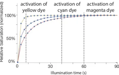
Our goal is to find activation time t (seconds) to increase the satura-tion of a base dye D 2 {C, M, Y} from X0% to X%. I first described how we experiment to get an activation graph: saturation percent over time. Then, I explained how to generalize the activation graph to continuous function via curve fitting and derive the equation. 4.1.1 Activation Experiment
Similar to the deactivation experiment in the prior work [4], we pre-pared three white cubes, each sprayed with a base dye C, M, or Y. To make sure that all cubes have 0% saturation for initial states, we deac-tivated them with white light first. Next, we start the UV projection and capture the image of the cube every 4 seconds for 10 minutes.
After we collected those images, our MATLAB program computes the average values (C, M, Y) of the cube image, captured from a cam-era and converted to CMY color space. Lastly, these avcam-erages for all frames are scaled to be 0% at the beginning at 100% at a converged time and plotted, as shown in the fig.1.
4.1.2 Activation Equation of a Single-Colored Dye
Let’s shining UV light for t seconds activates a 0% - saturated dye D 2 {C, M, Y} to aD(t) saturated percent. Thus, we need to find aC, aM, aY functions which best represent C, M, Y dye curves, re-spectively, as plotted in fig.1. Moreover, we also want these functions to be continuous, so that they work with our Gradient Descent opti-mization discussed later in chapter5.
Since the graph grows very quickly at the beginning and slows down until it converges, I chose a rectangular hyperbola function, which guarantees convergence, over a log function to represent this
14 dyes activation and deactivation
Figure 1: Effect of activating C, M, and Y base cubes with UV light. C, M, and Y dyes are fully activated at 40, 60, and 8 seconds, respectively.
trend. I use MATLAB curve fitting with a rectangular hyperbola equa-tion because it has similar manners with our experimental graph in fig1when it grows very fast and then converges. Specifically, the equa-tion I used for curve fitting is aD(t) = -100/(b· t + h) + (100/h). This is derived from (x - h)(y - k) = -c where the graph passes the origin What if the initial state of the dye is at X0% instead of 0%?
An extra step is identifying t0 that corresponds to the initial satu-ration percent. t0 is simply a-1D (X0) where a-1 is an invert function of a. Therefore, shining UV light for t results in saturation percent:
aD(t0+ t) = aD(a-1D (X0) + t) where a-1(X0) = X0h 2 (100 - X0h)b 4.2 deactivation
We want to answer how long (tl) we should shine visible light l 2 {r, g, b}1 a base dye D 2 {C, M, Y} to decrease saturation from X
0% to X%.
Deactivation involves three visible light red, green, and blue react-ing on all base dyes. Although we use the same base dyes and same visible light sources from the same VL projector as Photo-Chromeleon, we change the ratio of C, M, Y base dyes in our mixed dye to obtain better black color, so we need to redo the experiment.
1 We use three visible light wavelengths red, green, and blue light for deactivating C, M, and Y dyes
4.2 deactivation 15
4.2.1 Deactivation Experiment
Similar to the deactivation experiment in the prior work [4], we pre-pared three base cubes as explained in 4.1.1. To make sure that all cubes are 100% saturation at the beginning, we activated them with UV light for 10 minutes. Next, we start projecting three bars of r, g, b lights to a base cube. The bar is shrinking over time from left to right. This allows us to capture deactivation over time within a single image at the end of the experiment. Repeating this for all base cubes C, M, Y gives us three images shown in2
Figure 2: C, M, Y cubes are deactivated with red, green, and blue light for 1800 seconds in the first, second, and third row, respectively. Excep-tionally, the blue light is shone for 80 seconds because blue light deactivates yellow dye rapidly.
Note that this shrinking bar approach is simple but is not suitable for the activation experiment because when the shrunk part is a black pixel that cannot be fully turned off by projectors and have a lot of impact on activating dye since it is fast to activate.
Lastly, the MATLAB program computes how light affects a dye by splitting a bar into 40 pieces and compute the average values of them in similar manners to4.1.1. Thus, this is similar to capturing an image every 1800
40 = 45seconds for the red light that is shone 1800 seconds in total. Lastly, these averages for all frames are scaled to be 0% at the beginning at 100% at a converged time and plotted as shown in the fig.1.
16 dyes activation and deactivation
4.2.2 Deactivation Equation of a Single-Colored Dye
Let’s shining visible light l for tl seconds activates a 0%-saturated dye D 2 {C, M, Y} to dD,l(tl) saturated percent. Similar to Photo-Chromeleon [4], we use linear graphs to predict the deactivation ef-fect in fig.3.
Our deactivation with tlthen change the saturation percentage of the dye D by
dD,l( tl) =
-100· tl TD,l percent2 when T
D,l is the minimum illumination time of light l to fully deactivate the 100%-saturated dye D retrieved from fig.3.
What if the initial state of the dye is at X0% instead of 100%?
Since dD,lis linear, the change of saturation percent will be propor-tional to tl regardless of the initial state. Therefore, shining light l for tlseconds results in saturation percent:
dD,l( tl) = X0% + dD,l( tl)
5
I M P L E M E N TAT I O N
In this chapter, I explained the core work that allows users to update the photochromic-coated object surface from its current color texture to the desired color texture. This includes the optimization formula, Processing Program for the optimization, and the program speedup.
I started with how the preview images are created given dyes sat-uration percentage 4. Next, I explained how to derive optimization formula and how does it apply to the activation and deactivation phase. Then, I discussed the Processing program which computes op-timization and control projection. Lastly, I described the approach I used to make optimization work with users-friendly speed (within a minute).
5.1 optimization
Two main components that control the color of dyes are UV projector, which activates a dye from transparent to its color, and Visible Light (VL) Projector, which deactivates a dye from its color to transparent state.
Given a starting state S0 = (s0,C, s0,M, s0,Y) and a target state S= (sC, sM, sY)of a pixel, the optimization algorithm computes the optimal UV activation time and R, G, B deactivation time to update from starting state to the target state.
*Note that the state vector, represented by sDsaturation percent of base dye D, should not be confused with a color vector, represented by c, m, y color channel
the activation phase computes the minimum time tuvto shine UV light until the state has higher saturation than the target state, i.e. s0,D > sD for all D 2 {C, M, Y} dyes in the first iteration. For multi-iteration mode, later multi-iterations remove higher-saturation enforcement. So it acts very similar to the Deactivation Phase trying to come clos-est1 to the target state. In the best scenarios, t
uv = 0 because the starting color already has higher saturation.
the deactivation phase finds the shining duration of each red, green, blue light to reduce the saturation of the intermediate state re-sulting from the activation phase and come closest to the target state
1 The closeness is measured by the Euclidean distance
18 implementation
as possible.
In the following three sections, I explained the formula of our opti-mization used in both phases and then go into detail about how we solve the optimization work for each phase.
5.1.1 Formula
In this section, I explained how Gradient Descent, the well-known algorithm for optimization, is used in both phases to find optimal per-pixel shining time for UV projector and VL projector.
Gradient Descent is an optimization algorithm that iteratively up-dates a parameter x in the opposite decreasing direction2 with the increase of the function f(x) that we want to minimized. Denote x(i) is a predicted x after i iterations, hoping that x(i+1) 6 x(i), when 0 6 i 6 n where n-th the final iteration with convergent iteration where f(x(i+1)) - f(x(i))is zero or very small.
In our problem, given a single pixel starting state S0 = (s0,C, s0,M, s0,Y) and a target pixel state S = (sC, sM, sY), we want to find a duration of time tl to shine light l (uv (uv), red (r), green (g), and blue (b)) from projectors so that the light increases or decreases the saturation percentage to be closest to S.
The definition of closeness between these two state S and S0 can be defined as Euclidean Distance, for simplicity, without the square root:
(sC- sC0 )2+ (sM- sM0 )2+ (sY- sY0)2
Note that this simplification doesn’t change the gradient descent re-sult because f(x) is minimize (f(t))2 when f(t)> 0.
Having stated the problem and how I wanted to solve it, I wil go into more detail about how to arrive at optimal tuv in the activation phase through UV projector and trgb = (tr, tg, tb) in deactivation phase via visible light projector.
5.1.2 Activation
During the activation phase, a UV light projector shines UV light to on saturated dye for tuvseconds. I first described the activation func-tion that computes a resulting state of a mixed dye after activafunc-tion.
5.1 optimization 19
Then, I explained how this is used in activation optimization to com-pute optimal tuv.
5.1.2.1 Activation Function of a Multi-Color Dye
Recall that an activation function of a single-color dye D is aD(t) = aD(t0+ t) = aD(a-1D (s0,D) + t)
when t correspond to the time it took the dye D are activated from transparent to color.
Since a single-colored dye D can be at any arbitrary state, i.e. arbri-trary points on activation graphs, its corresponding t0,Dcan be differ-ent among differdiffer-ent D. Thus, the activation equation can be written as A(S0, tuv) = 2 6 6 4 aC(a-1C (s0,C) + tuv) aM(a-1M(s0,M) + tuv) aY(a-1Y (s0,Y) + tuv) 3 7 7 5
Thus, we get A activation function that computes the resulting state A(S0, tuv)after activating a mixed dye from the starting state S0 with UV light for tuvseconds.
5.1.2.2 The Gradient Descent of Activation Phrase
In the gradient descent algorithm, each iteration will update a shin-ing duration for UV light tuv.The iterative equation of our Gradient Descent can be written as follow
t(i+1)uv = t(i)uv+ ⌘f0(t(i)uv) where
f(tuv) = (sC- AC(S0, tuv))2+ (sM- AM(S0, tuv))2+ (sY- AY(S0, tuv))2 The gradient of our error function f(tuv)we want to minimize is
f0(tuv) = -2AC0(S0, tuv)· (sC- AC(S0, tuv)) - 2AM0 (S0, tuv)· (sM- AM(S0, tuv)) - 2AY0(S0, tuv)· (sY- AY(S0, tuv)) AD(S0, tuv) = aD(t0+ tuv) = -100 b(t0+ tuv) + h +100 h AD0 (S0, tuv) = -100 b(t0+ tuv) + h +100 h = 100b (b(t0+ tuv) + h)2
20 implementation
oversaturation in the first iteration As mentioned at the beginning of this chapter, the first activation (first iteration) has oversaturation requirements. So, if any dye activates too far beyond the target state wanted, we don’t penalize that in the error. In other words, if sD- AD(S0, tuv) < 0, we set it to 0 in f(tuv)equation.
This oversaturation in the first round serves to avoid the case that the program returns too small tuv when a dye’s saturation is higher than its target saturation, while the other dye hasn’t reached its target saturation yet. In this case, increasing tuv to enhance saturation per-centage adds error much more than decrease error. So, the gradient descent will stop. This can make some color impossible to achieve. That is why we oversaturate the dyes in the first round, knowing that deactivation will help decrease the oversaturated dyes.
Meanwhile, we need to discard this oversaturation requirement for later iteration to avoid it turning to black and try to deactivate again just to end up with the inputted color of its iteration.
5.1.3 Deactivation
During the deactivation phase, red, green, and blue lights are shone from a visible light projector simultaneously. For example, if the opti-mal solution is to shine red light for 300 seconds and green for 100s, the VL projector shines yellow light for that pixel for 100s and red for 200s. This mean the time it take to deactivate each pixel is then max(tr, tg, tb).
The deactivation impact of all lights on each dye is a sum of impact of each light (more detail in the next section Deactivation Function section. For example, if we start with 100% the Cyan dye, and shine red light 300s and green light 200s which deactivates the Cyan dye by 50% and 10%, respectively, but with the effect of both lights, the Cyan dye is deactivated by 60% and becomes 40% saturated.
5.1.3.1 Deactivation Function of a Multi-Color Dye
Recall that a deactivation function of a single-color dye D via light l is
dD,l(tl) = s0,D+ dD,l(tl)
when tl correspond to how far the dye D are deactivated from fully saturated state.
Dye D at S0 state is deactivated by all light for t = (tR, tG, tB) seconds accumulatively, so it resulting state becomes
5.2 processing program 21
Since we use linear graph to represent deactivation as derived in
4.2.2, we no longer need to worry about different starting state of each dye (difference of t0 among all dyes).
D 0 B B @S0, t = 2 6 6 4 tR tG tB 3 7 7 5 1 C C A = 2 6 6 4 s0,C+ dC,R(tR) + dC,G(tG) + dC,B(tB) s0,M+ dM,R(tR) + dM,G(tG) + dM,B(tB)
s0,Y+ dY,R(tR) + dY,G(tG) + dY,B(tB) 3 7 7 5 Thus, we get D deactivation function that computes the resulting state D(S0, t) after activating a mixed dye from the starting state S0 with visible light for t = (tR, tG, tB)seconds.
5.1.3.2 The Gradient Descent of Deactivation Phrase
In the gradient descent algorithm, each iteration will update a shining duration for each light tlindependently.The iterative equation of our Gradient Descent can be written as follows:
t(i+1)l = t(i)l + ⌘f0(t(i)l ) where
f(tl) = (sC- DC(S0, tl))2+ (sM- DM(S0, tl))2+ (sY- DY(S0, tl))2 The gradient of our error function f(tl)we want to minimize is
f0(tl) = -2DC0 (S0, tl)· (sC- DC(S0, tl)) - 2DM0 (S0, tl)· (sM- DM(S0, tl)) - 2DY0(S0, tl)· (sY- DY(S0, tl)) when DD(S0, tl) = sD,C+ dD,l(tl) and DD0 (S0, tl) = dD,l0 (tl) = -100 TD,l (see dD,lequation in4.2.2) 5.2 processing program 5.2.1 Color and Preview
After I had activation and deactivation equations ready from the ex-periment in chapter4, I needed to derive color of each pixel given the pixel state, which is its C, M, Y saturation percentages.
22 implementation
Similar to Photo-Chromeleon [4], we estimated the color of mixed dye by summing up the color values from three base dyes. When a dye D has sD saturation percentage, its estimated color is sD· D⇤, when D⇤a color at the 100% saturation, obtained by averaging fully-activated D cube image in CMY color mode3as shown in fig.2.
Hence, a mixed color X is X = sCC⇤+ sMM⇤+ sYY⇤where X, C⇤, M⇤, Y⇤ are a 3-dimension vector as shown below.
2 6 6 4 Xc Xm Xy 3 7 7 5 = sC 2 6 6 4 C⇤c C⇤m C⇤y 3 7 7 5 + sM 2 6 6 4 M⇤c M⇤m M⇤y 3 7 7 5 + sY 2 6 6 4 Yc⇤ Ym⇤ Yy⇤ 3 7 7 5 5.2.2 Optimization
Optimization can contain multiple iterations: each iteration is a se-quence of activation and deactivation based on the resulting state in the previous phase4.
Optimization starts the first phrase, activation: computing optimal tuv,i activation time, as in 5.1.2, for each pixel i to come closest to the target color of that pixel. The optimization for each pixel is done parallel as discussed in 5.3. After the solution tuv,i to every pixel i is available, the program finds the activation phrase duration TUV = max(tuv,0, tuv,1, ...), which will be used in the5.2.3.
Then, the optimization starts the second phrase, deactivation: com-puting best (tr, tg, tb)shining time for all pixels in the similar manner to the first phrase. Then it computes the deactivation phrase duration TVL= max(tr,0, tg,0, tb,0, tr,1, tg,1, tb,1, ...).
If users enable multi-iterations optimization, the optimization con-tinues feeding the current saturation state and repeating activation and deactivation.
For each pixel, we stores t = (tuv, tr, tg, tb)for all iterations. 5.2.3 Projection
After optimal time for all iterations are in hand, we need to translate the optimal time to a sequence of images to be shone by the projector.
3 Throughout this work, we use CMY color mode, so each color is represented by a 3D vector (c, m, y). In the perfect world, we want C, M, Y dyes to be pure c, m, y colored: (255, 0, 0), (0, 255, 0) and (0, 0, 255), so we acknowledge the limitation of the color space that our work can provide.
4 A phrase refers to an activation or deactivation, while an iteration refers to activation and deactivation.
5.3 software speedup 23
For the UV projector, the white pixel is full intensity. For VL projector, our red, green and blue light (r, g, b) = (255,0,0), (0,255,0), (0,0,255) respectively.
5.2.3.1 Activation Projection
For controlling UV projection, the projector requires 1-bit BMP image with a sequencer file telling how long each image will be displayed, set to 200ms (5fps) for all frames.
When the optimization completes, the program generates UV pro-jection images by setting pixels that need UV activation during the current frame’s timestamp, ts6 tuv5, to white, otherwise, to black.
The program uploads these UV projection images to the UV projec-tor. At this point, we start the timer and turn the projector off when it reaches TUV seconds and move on to the second phrase, deactivation. **Note that there’s no concern about the speed of image generation because activation duration is only a minute.
5.2.3.2 Deactivation Projection
Unlike the UV projector, the VL projector behaves like an external monitor, so we can set the canvas pixel color and make the effect appear instantaneously. Once activation projection finishes, the VL projector starts real-time frame update as follows
At the current timestamp6 ts, it checks each pixel if the light l should be on or whether, in this phase, ts6 tl+ TUV7. If it should be on, Clwill be set to 255 in the color pixel C = (Cr, Cg, Cb) of the VL screen; otherwise Cl remains zero.
*** Note that we choose to shine 255 and not other lower value since this full intensity shortens the duration of the shines.
5.3 software speedup
Since the average number of iteration of gradient descent until it con-verges is around 10000 iterations. Doing this for 800x600 image size can takes 800x600x10000 4.8billion iterations. This number of itera-tion cannot be done in less than 5 minutes, so I explored ways to
5 ts is the current timestamp of a time frame relative to the beginning of this activation phrase. tuvis activation duration of a pixel in the specific phrase as produced in
optimization steps
6 current timestamp is reset to 0 at the beginning of each iteration. 7 A pixel’s tland TUV produced in optimization steps
24 implementation
speed it up and reduce the number of computation.
The three approaches used are 1. One-color caching storing only the pixel’s most recent optimization result. 2. Dense Data Structure storing only object pixels, i.e., ignoring all background pixels while optimizing, computing saturation states, image exporting and project-ing. 3. Multi-threading to compute optimization in a parallel manner for all pixels. The first two help speed up by reducing the number of computations, while the third helps speed up by leveraging the multi-core hardware.
5.3.1 Optimization One-Color Caching
In Photo-Chromeleon [4], Jin et al. computes optimization only dur-ing deactivation phrase to find VL projection time t = (tr, tg, tb) to deactivate black color to a target color (c, m, y). Thus, they can store VL projection time t of all 2563 ⇡ 16 million possible target colors in the cache and give them a huge advantage of reusing old calculations. Moreover, they can improve further by precomputing and saving all the optimization result once in the file, and reuse them forever.
However, the full caching approach is not feasible because we want to update it from any starting color. Therefore, the input space size is squared, (2563)2 = 2566 ⇡ 281 trillion possibilities.
We then proposed caching every single latest result of optimiza-tion because, for most images, the colors of the consecutive pixels are likely to be the same or very close, for instance, sky, wall, grass, etc. However, since the probability of both starting and ending saturation state being the same as the previous pixel is very low, we relax our check by allowing some threshold difference, currently set to 5 when the channel value is 0 - 255.
5.3.2 Dense Data Structure
Before my work, the program stores 16 million pixels of full-HD 1080p VL projection screen. There are multiple tasks that program performs on these pixels, including optimization, exporting an image for activation projection, setting pixel colors for deactivation projec-tion, and computing saturation state after each phase to produce an initial state of the next phase.
Since the background pixels generally occupied a substantial per-centage of images, we can avoid unnecessary task on background pixel by storing and using object pixels instead.
I then only store starting state, target state, projection time output of optimization, and the mapping between this object pixel to the
cor-5.3 software speedup 25
responding pixel position on UV and VL projector. This dense data helps save memory space as well as overhead from looping and check-ing non-background every time.
Moreover, one might argue that skipping the loop isn’t much slower and is simpler. However, the dense structure is preferable for a multi-threading program so that the program can balance working tasks to different threads. Meanwhile, the sparse data can end up with one thread only having 10 object pixels to perform tasks ended up waiting while another thread is performing tasks for 10,000 pixels.
Instead of looping through 1920x1080 ⇡ 2million pixels, the pro-gram now only needs to perform tasks on 50K for Chameleon and 10Kpixels for the cube.
5.3.3 Multi-threading
Another significant speed-up comes from multi-threading. Currently, I used eight threads and assign N/8 object pixels equally. I made sure to preserve the object pixels in left to right, top to bottom order before splitting them. This helps increase the cache hit rate because the memory layout of the image and matrix are stored in row-major order.
Since each phase depends on the result of the previous phase, I only parallelized the same work among different pixels, such as com-puting optimization, calculating the resulting state.
6
E VA L U AT I O N
After a system has been setup such that users can update the color of any part of an object’s color texture to another color texture, we want to evaluate how well the system performs. In this chapter, I evalu-ate our projection and computation time of our system to prove how ChromoUpdate is twice as fast as the traditional UV LED activation approach.
6.1 projection time improvement
To evaluate a speedup from pixel-wise activation with a UV projector compared to black activation with a UV LED in Photo-Chromeleon [4], I divided evaluation into three scenarios based on users’ use cases.
1. Texture Creation: updating from a white texture to a texture. 2. Re-saturation: updating from a fainted texture to its more
satu-rated version.
3. Partial Update: updating from a texture to its partially modified version.
The first scenerio indicates the better off we get from switching UV light source. The second scenerios tell us how much we gain from direct color transition when the color is similar. Finally, the third scenerios shows transition between two colors that are more distinct than the second case.
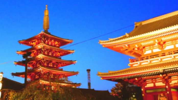
Focusing on the application scenarios, the example image we used is Sansoji temple in Japan as shown in the fig.4.
Before starting, I wanted to clarify that I didn’t run the Photo-Chromeleon [4] program to get the projection time from the activating-to-black approach. Instead, I ran our modified version, which forces activation of all pixels to be a minute equally. This 1-minute activa-tion makes sure that regardless of starting color texture, all pixels turn black as worked in Photo-Chromeleon [4] before deactivation.
This way, I made sure I compared the logic of activation itself with-out other programs or hardware variants that can impact projection time. Some examples of these variants are different UV light sources,
28 evaluation
Figure 4: Sansoji temple image with size 1080x1920
ratios of the base dye mixed, and gradient descent converging thresh-old.
6.1.1 Texture Creation
To evaluate texture creation, we start from white pattern and want to get the temple pattern from the projection.
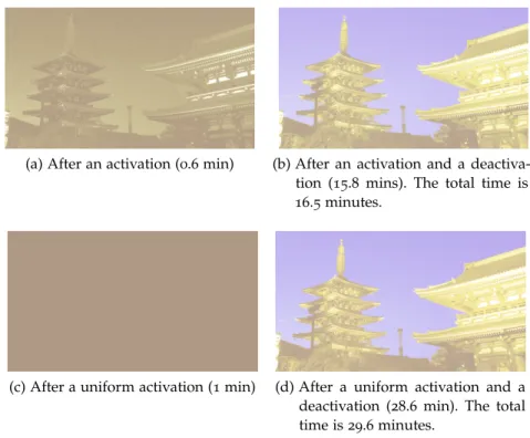
The digital preview of results from two approaches, pixel-wise acti-vation and uniform actiacti-vation, are shown in fig.5that using the pixel-wise activation can reduce the time by 44% from 29.6 minutes to 16.5 minutes.
The big advantage of using UV projector is, as seen in fig.5b, the gray-scale activation when the lower-saturation than 100% is enough to get the desired color. This gray-scale helps prevent unnecessary sat-uration and save us time huge unnecessary slow-phase deactivation. 6.1.2 Re-saturation
In the re-saturation case, we are interested in 100% saturation of im-age get deactivate from light environment.
I reduced saturation of the temple image to around 75% and up-dated it to 100% saturated texture. Our projection takes 12.2 minutes from 0.5 minutes of activation and 11.7 minutes of deactivation.
Therefore, if users already have a faint texture on their objects, they can save time by 59% switching from UV LED to UV projector. Apart from the benefit of changing the UV light source, we also gain ben-efits from the direct transition from the fainter version to the full saturated color texture. Re-saturating time helps save 25% more time than creating the surface from scratch with a UV projector in the first
6.1 projection time improvement 29
(a) After an activation (0.6 min) (b) After an activation and a deactiva-tion (15.8 mins). The total time is 16.5 minutes.
(c) After a uniform activation (1 min) (d) After a uniform activation and a deactivation (28.6 min). The total time is 29.6 minutes.
Figure 5: The first row displays digitally preview result after two phases of projection from the pixel-wise activation used in ChromoUpdate. The second row displays the result from uniform activation used in Photo-Chromeleon [4]
scenario.
(a) The color pattern before re-saturated: 75% saturation tem-ple pattern
(b) The pattern after the activa-tion with the UV projector
(c) The pattern after re-saturated to 100%
Figure 6: Re-saturation Experiment
6.1.3 Partial Update
In this evaluation, I started with the temple image and made the two following updates using Photoshop: 1. retouching, adding a text, drawing with a brush tool in (fig.7a), and 2. adding an effect to the text and the drawing (fig.7b).
30 evaluation
(a) I first retouched the image to remove a black diagonal wire in fig.4. Then, I added the text and draw a heart.
(b) I add a shadow effect to the text and the heart.
Figure 7: Two images represent two users designs iterations in order.
The result in fig8shows that the update takes around 11.7 minutes. I also input both of these texture to UV LED and our approach cre-ating from scratch. The UV LED method took 27.9 minutes for both. Therefore, ChromoUpdate save users’ waiting time by 60%.
Besides, we wanted to know the benefit of having the object that has the temple texture on it compared to have not. When I used ChromoUpdate to create from scratch, it took 16.7 minutes. There-fore, with the temple texture ready, the update performs faster by 30%, which helps users perform more design iterations.
In summary, compared to the uniform activation approach used by Photo-Chromeleon [4], the per-pixel activation approach used by ChromoUpdate has 44%, 59%, and 60% shorter projection time for creation from scratch, re-saturation, and partial update, respectively. This contributes to around 54% or half. Meanwhile, I also showed that updating from an existing texture outperform creating from scratch by 25% and 30% for re-saturation and updating, respectively. Hence, the ChromoUpdate provides a significant improvement in projection time and supporting update and re-saturation cases for design itera-tions well.
6.2 program performance
To evaluate the program performances, I timed the program optimiza-tion computaoptimiza-tion duraoptimiza-tion with a full resoluoptimiza-tion of our screen size 1080p.
The three speeding up approaches in 5.3 are 1. one-color caching, 2. dense data structure and 3. multi-threading. I mainly focused on evaluating one-color and multi-threading because dense data
struc-6.2 program performance 31
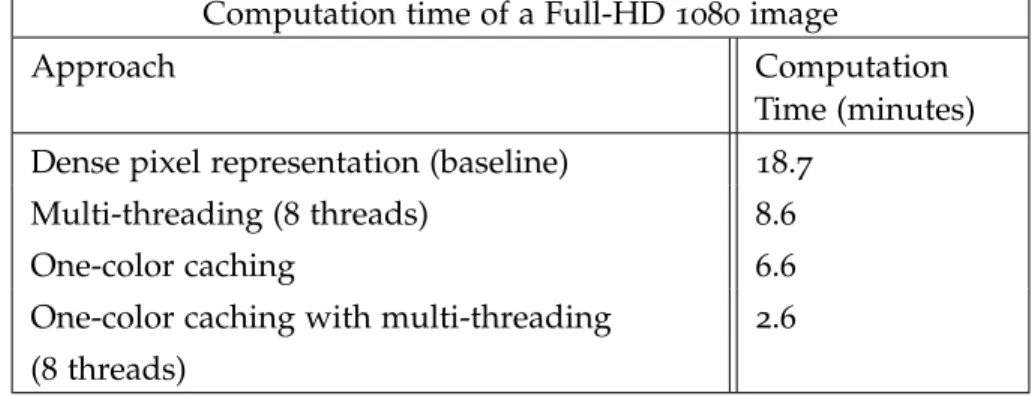
ture serves to avoid poor balancing numbers of tasks per thread. After I had a dense data structure of object pixels, I measured the computation time for a full-HD 1080p (1920x1080 ⇡ 2 million pixels) texture and use this as our baseline. Without further optimization, it takes 18.7 minutes to compute the optimization for an image as shown in the table9.
One-color caching is the winner, speeding up by three times to 6.6 minutes. Multi-threading of 8 threads further improve the speed by another 2.5 times to 2.6 minutes.
In a combination of these three approaches, the program speeds up by seven times and allows us to operate on a hull-HD 1080p image size in a few minutes. Note that in our real projection, the object we have seen so far is typically small because it needs to fit inside the system box, and take up far less than 30% of the entire screen. The computation is then generally done in 1-30 seconds. However, this speedup is important to make system scale well to support the bigger objects and the bigger system in the future.
32 evaluation
(a) The 1stupdate: after activation (0.5 mins).
(b) The 1stupdate: after deactivation (11.6 mins). Total
time for the 1stupdate is 12 mins
(c) The 2ndupdate: after activation (0.6 mins)
(d) After a pixel-wise activation and a deactivation (10.8 min). Total time for the 2nd update is 11.4
minutes.
Figure 8: Preview of result updating the text and shadow on mug. Each update takes around 11-12 minutes.
6.2 program performance 33
Computation time of a Full-HD 1080 image
Approach Computation
Time (minutes) Dense pixel representation (baseline) 18.7
Multi-threading (8 threads) 8.6
One-color caching 6.6
One-color caching with multi-threading 2.6 (8 threads)
Figure 9: Computation time of different approaches for speeding up and its combination when computing optimization for the 1080p image.
7
D I S C U S S I O N A N D C O N C L U S I O N 7.1 discussion
ChromoUpdate contributes to success in local updating the texture and reducing projection time significantly for local updates and re-saturation. However, this project has limitations, including long pro-jection time for completely different two images, error from UV light black pixel activation, requiring users to input the texture and non-long-lasting texture.
7.1.1 The Worst-Case Projection Time
Based on the experiment we have so far, our work performs well with partial updating and re-saturating. However, we acknowledge that only a single pixel that spends the longest time requires users to wait until this slow projection finished. This means our system will take as long as a traditional approach from Photo-Chromeleon.
Also, this is unavoidable if we want every single pixel to be exactly what users want. However, we want to seek a way to reduce this probability of having noise or a small number of pixels that ruins the rest.
This situation might be rare for updating and should not happen with the re-saturating process. On the other hand, if we update from one image to completely new image, this has a higher chance that we find a pair of the starting state and target state that takes a long time to complete.
This is not a big concern for single iteration optimization mode because activation worst case is a minute, and during deactivation, users can stop if they don’t see many pixels VL projectors are shining. However, for multi-iterations optimization mode, a single slow pixel can delay the next iteration for half an hour even if all the other pixels finish in 5 minutes.
Currently, our system allows users to press the button to start the next iteration at any time, but it is not convenient if they have to wait until they spot the issue to end or skip it.
One way to work around this problem is finding the time tk at k-th percentile in an unsorted array in linear time, and update all
36 discussion and conclusion
tl = min(tl, tk). For example, if a projector completes deactivation of 95% of updating pixels, we proceed to the next step. We can further make an algorithm to determine appropriate cut off to handle more complex cases.
7.1.2 Black Pixel Effect
Even though we shine black pixels when UV and VL light is off, the projector still shine some light on it. We experimented with how much black pixels from UV and VL projector can affect the color. We don’t spot non-negligible effects from the VL projector but spot a prominent effect from UV light. In this experiment, we shine a minute of black pixel to all 0%-sat base cubes.
With this hardware limitation of nowadays projectors, we propose to correct this during optimization. One approach is adding this acti-vation effect of black pixel to the resulting state so that deactiacti-vation can decrease further.
I propose that instead of shining the white pixel (full power), we shine gray pixels for the one that ends early. This approach does not add extra deactivation projection duration and is simpler. The more straightforward version is setting pixel value to tuv
TUV · 255 rather than
255 at the end of phase once TUV is known. Still, this assumes that the intensity control by 0-255 is linearly scaled, so we might need fur-ther experiments to understand how gray pixels behave. Moreover, we need to make sure that this correct didn’t make the color result worse.
7.1.3 Object Texture
Currently, we require users to input the current texture of the object. With multi-round mode, we provide auto-saved and load dyes per-centage, which so that users can continue updating as much as they want. However, it is much more convenient if our program automate this by using camera system.
In future work, we would like to detect the current color texture from the camera. However, this can be challenging when we need to make sure that the camera view aligns precisely with all the rest of our projection. We are working on that system, but the alignment is still off by more than 3mm, which makes per-pixel optimization and projection impossible. Moreover, getting accurate color is also hard
7.2 conclusion 37
due to white balancing and brightness adjustment.
7.1.4 Alternative Materials for Deactivation Speedup and Durability Currently, it can take 40 minutes to create a texture from scratch, while the texture only lasts for a day, so the duration users need to wait until the texture is ready is long compared to the duration it lasts.
To improve users’ experiences, ChromoUpdate provides a system that supports quick saturation. However, requiring users to re-saturate the object often is still not convenient, so we should find a way to reduce projection time and increase the durability of our coating.
I propose we explore T-type photochromic dyes, which transforms from colored to transparent via heat [10] [6].
PIC, a T-type photochromic compound, can be reverted to transpar-ent state thermally, and its length can be tuned by molecular design to be in nanoseconds up to ten seconds scale[5]. It is interesting to ex-plore whether there are T-type compounds that allows deactivation to be accelerated by heat, and controlled the saturation in finer-grain level with visible light.
Next, we want to have long lasting texture. Yellow dye is fully de-activated by 5 hours under indoor lightning, while the most durable dye, Cyan, disappears only after 26 hours [4]. Upon exploring T-type materials further, we might found a possibility to preserve the color of the dye at a low temperature. There is not much research I found in this area, so we need to explore and experiment more to check the possibility. this area, so we needs to explore and experiment more to check the possibility.
7.2 conclusion
In the ChromoUpdate project, I was responsible for implementing the optimization algorithm to update from one color directly to another texture and make the system support local update and re-saturation. To support the direct color transition, I also needed to speed up the program to make sure the optimization is feasible.
By introducing a UV projector and supporting the direct per-pixel activation, ChromoUpdate speeds up projection time by half. Use cases vary the speed: updating and re-saturating cases are generally faster than re-creating texture from scratch. With this support and speed up, we provide better and faster tools for re-programming mul-ticolor texture and design iterations.
B I B L I O G R A P H Y
[1] Yamada Chemicals Co. Photochromic Dyes. Retrieved May 1, 2020 from https://ymdchem.com/en/publics/index/87/.
[2] Tomoko Hashida, Yasuaki Kakehi, and Takeshi Naemura. “Pho-tochromic canvas drawing with patterned light.” In: Proceedings of ACM SIGGRAPH 2010 Posters (SIGGRAPH’10). 2010.
[3] Tomoko Hashida, Yasuaki Kakehi, and Takeshi Naemura. “Pho-tochromic sculpture: volumetric color-forming pixels.” In: Pro-ceedings of ACM SIGGRAPH 2011 Emerging Technologies (SIG-GRAPH ’11). 2011.
[4] Yuhua Jin, Isabel Qamar, Michael Wessely, Aradhana Adhikari, Katarina Bulovic, Parinya Punpongsanon, and Stefanie Mueller. “Photo-Chromeleon: Re-Programmable Multi-Color Textures
Us-ing Photochromic Dyes.” In: ProceedUs-ings of the 32nd Annual ACM Symposium on User Interface Software and Technology (UIST ’19). New York, NY, USA: ACM Press, Oct. 2019, 701–712.
[5] Yoichi Kobayashi, Yukie Mamiya, Katsuya Mutoh, Hikaru So-tome, Masafumi Koga, Hiroshi Miyasaka, and Jiro Abe. “Ex-cited state dynamics for visible-light sensitization of a photochromic benzil-subsituted phenoxyl-imidazolyl radical.” In: Beilstein J Org Chem 15 (2019), 2369-2379.
[6] Keitaro Nakatani, Jonathan Piard, Pei Yu, and Rémi Métivier. “Introduction: Organic Photochromic Molecules.” In: June 2016, pp. 1–45. isbn: 9783527337798. doi: 10 . 1002 / 9783527683734 . ch1.
[7] Machi Miyahara Atsumi Osada Sae Takeshita and Masa Inak-age. “KAMI CHAT.” In: Proceedings of the 2008 International Con-ference on Advances in Computer Entertainment Technology (ACE ’08). 2008, p. 403.
[8] Parinya Punpongsanon, Xin Wen, David Kim, and Stefanie Mueller. “ColorMod: Recoloring 3D Printed Objects using Photochromic
Inks.” In: Proceedings of the 2018 CHI Conference on Human Fac-tors in Computing Systems (CHI ’18). 2018, p. 213.
[9] Kohei Nishimura Tomoko Hashida Takeshi Naemura Daniel Saakes Takahiro Tsujii. “Photochromic Carpet: Playful Floor Canvas with Color-Changing Footprints.” In: Proceedings of the 11th Conference on Advances in Computer Entertainment Technology (ACE ’13). Springer International Publishing, Nov. 2013, pp. 622– 625.
40 bibliography
[10] Andy Towns. “Colorant, Photochromic.” In: July 2016, pp. 447– 455. isbn: 978-1-4419-8071-7. doi: 10.1007/978- 1- 4419- 8071-7_163.