Code Versioning in a Workflow Management
System
by
P. Alexander Rolfe
Submitted to the Department of Electrical Engineering and Computer
Science
in partial fulfillment of the requirements for the degree of
Master of Engineering in Computer Science and Engineering
at the
MASSACHUSETTS INSTITUTE OF TECHNOLOGY
May 2002
@
P. Alexander Rolfe, MMII. All rights reserved.
The author hereby grants to MIT permission to reproduce and
distribute publicly paper and electronic copies of this thesis document
in whole or in part.
I
MASSACHUSETTS INSTAuthor ..
Department of Electrical Engineering and Computer Science
May 24, 2002
Certified by..
Michael D. Ernst
Assistant Professor
Thesis Supervisor
Accepted by...
Arthur C. Smith
Chairman, Department Committee on Graduate Students
BPARKER
ITUTE OF TIECHNULUYJUL 3 1 2002
LIBRARIES tCode Versioning in a Workflow Management System
by
P. Alexander Rolfe
Submitted to the Department of Electrical Engineering and Computer Science on May 24, 2002, in partial fulfillment of the
requirements for the degree of
Master of Engineering in Computer Science and Engineering
Abstract
Workflow systems implement process definitions in laboratory, office, and industrial settings. In many cases, the process definition is implicit in the ad-hoc software written for a particular task. In other cases, a generic framework provides basic functionality and structure, offering quicker development and advanced features. Few workflow systems handle changes in the process definition or the implementing code. This work shows that complicated workflow processes can be composed of a few simple primitives and that changes in the workflow structure and code can be managed effectively.
Thesis Supervisor: Michael D. Ernst Title: Assistant Professor
Acknowledgments
My thanks goes to Michael Ernst for supervising this thesis and to Brian Gilman and
the Whitehead Institute/MIT Center for Genome Research for supporting the work.
I also owe much of my inspiration and insight into the problems of workflow systems
to the LIMS group at the Genome Center: Brian Gilman, Erich Stahl, Will Fitzhugh, Ralph Santos, Andrew Zimmer, Daniel Richter, and Catherine Hosage Norton, and Jay Ireland.
Contents
1 Introduction 13
1.1 W hy Are Workflow Systems Useful? . . . . 14
1.2 Definitions . . . . 15
1.3 Workflow Change . . . . 16
1.4 Related Systems and Other Work . . . . 17
1.4.1 Workflow Management Coalition . . . . 18
1.4.2 LabBase and LabFlow . . . . 19
1.4.3 MicroWorkflow . . . . 20
1.4.4 Dynamic Workflow Modification . . . . 20
1.4.5 Ad Hoc Workflow . . . . 21
2 Design of a Workflow System 23 2.1 Assumptions . . . . 23 2.2 Requirements . . . . 24 2.3 System Components . . . . 27 2.3.1 Workflow Description . . . . 28 2.3.2 Translation . . . . 30 2.3.3 User Interface . . . . 30 2.3.4 User Code . . . . 30 2.3.5 Workflow Engine . . . . 31 2.3.6 Workflow Storage . . . . 33
3 System Implementation 37
3.1 W orkflow Description Classes . . . . 37
3.2 Base Runtime classes . . . . 40
3.2.1 Materials . . . . 40
3.2.2 Events . . . . 40
3.2.3 Storable . . . . 41
3.2.4 Listeners . . . . 42
3.3 W orkflow Storage Component . . . . 44
3.3.1 Process Definition. . . . . 44
3.3.2 Process Instance Status . . . . 44
3.3.3 Process History . . . . 45
3.3.4 RDBMS Dependencies . . . . 45
3.4 Runtime Engine . . . . 46
3.5 Workflow Design Tool . . . . 49
3.6 Implementing Translation . . . . 51
3.6.1 Sub-W orkflow . . . . 51
3.6.2 W orkflow Chaining . . . . 54
3.6.3 Blocking and Scheduling . . . . 54
3.6.4 Non-Determinism . . . . 54 4 Versioning 57 4.1 Types of Changes . . . . 57 4.1.1 Structural Change . . . . 58 4.1.2 Parameter Change . . . . 59 4.1.3 Code Change . . . . 59
4.1.4 Global or Limited Changes. . . . . 59
4.2 Design . . . . 60
4.3 Implementation . . . . 61
4.3.1 Rewriting . . . . 62
4.3.3 Workflow Engine and Storage . . . . 65
4.4 Other Approaches to Versioning . . . . 65
5 Potential Features 67
5.1 Constraint Checking . . . . 67 5.2 Data Flow Analysis . . . . 70 5.3 Interfaces to Other Languages . . . . 70
6 Conclusion 71
6.1 Evaluation . . . . 71 6.2 Contributions . . . . 72
A Workflow Storage Schema 73
B System Performance 77
B.1 Dispatching Events to the Initial State . . . . 78
List of Figures
1-1 A Sample W orkflow ... 17
2-1 An Example High Level Workflow Description ... 25
2-2 Major System Components . . . . 35
3-1 Runtime Dataflow . . . . 38
3-2 Low level workflow description classes . . . . 39
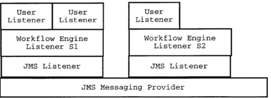
3-3 JMS Implementation: Layers of Listeners . . . . 46
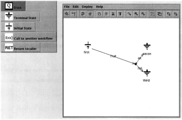
3-4 Process Design Tool Screenshot . . . . 50
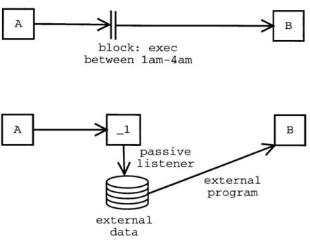
3-5 Implementing Blocking or Scheduling . . . . 55
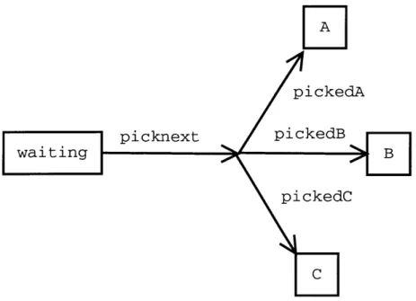
3-6 Using Extra States to Model Nondeterminism . . . . 56
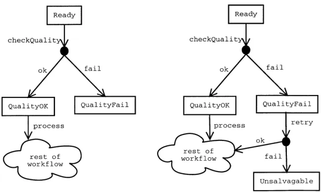
4-1 An Example of Structural Change to a Workflow Process . . . . 58
4-2 Mapping Class Name and Version to New Name . . . . 63
5-1 Constraint Checking as a Translated Feature . . . . 69
Chapter 1
Introduction
Workflow Management Systems enact process definitions, manage the resulting pro-cess instances, and report on the results. Unlike traditional software propro-cesses, the Workflow process often involves both computational work and physical work that exists outside the computer system. Steps in the process generally involve a single, well defined input and no global state. For example, a bank considers each loan appli-cation independently using a well defined process and might use a Workflow System to organize the activities and data related to loan approval. While the same process could be implemented by custom software written for a particular task, a Workflow Management System provides a framework and pre-built functionality. The Work-flow Management System described in this work provides a modular system that can implement most process definitions and conveniently handles changes to those definitions.
Our work makes two contributions to the study of Workflow Management Systems
by addressing extensibility and change. We describe the design and implementation of
our workflow system that allows complicated functionality to be created with a mini-mal set of primitives. Our system allows users to employ their own implementation or reuse a previous implementation of advanced features if the default implementation is unsuitable. Our system also encourages programmers to write reusable code that may be used with multiple processes. Furthermore, our implementation remains simple even as users add features because the features are built on top of the system rather
than integrated into the core. Many other systems provide complex primitives for scheduling, authorization, roles, worklists, containers, and domain-specific features. In doing so, they frequently prevent extensibility, lock the user into the provided feature implementation, and make the core system difficult to maintain.
While many Workflow Management Systems model processes, few model the changes that may occur in a process. Our second contribution is to discuss the design and implementation of extensions to handle revisions to a Workflow process. In particular, we address the problem of running multiple versions of a process simul-taneously.
Before considering Workflow Management Systems further, we present a short case for their utility. Then we define the terms that we will use in our discussions and introduce the problem of change in workflow systems. Our introduction to workflows concludes with a brief survey of other Workflow Management Systems.
The second chapter of this work describes the design requirements and design decisions made for the implementation of our Workflow Management System. Chap-ter three describes our implementation. ChapChap-ter four describes modifications to our system to support change in the workflow schema or code. Chapter five discusses several potential features that we have not yet implemented.
1.1
Why Are Workflow Systems Useful?
Consider a high throughput scientific research laboratory such as the Whitehead Genome Center where a researcher has asked a programmer for support in a project that involves laboratory and computational work to perform thousands or millions of experiments per week. The programmer must produce a software system that can take input from the researcher, create worklists for the laboratory technicians, accept laboratory results, record data, perform analyses of the data, and provide statistics and reports about the throughput of the whole project.
Projects often start on a small scale. Sometimes the researcher abandons the project because of poor results. In other cases, the experiments work well and the
project is scaled up dramatically. Without suitable tools, the programmer must write the system from scratch, requiring decisions about how much time to spend building software infrastructure. Since she cannot predict which course a project will follow, a developer cannot justify a large time investment to create custom software to manage the data for the project. For example, writing a comprehensive reporting suite that can track data through whatever ad-hoc pipeline the programmer has created will take a long time. Even if the programmer were willing to devote the necessary time, the researcher probably doesn't want to wait months or years to start their work.
Without tools, the programmer may repeat errors made by implementors of pre-vious systems [6, 7]. Experience shows that systems built without the appropriate tools tend to be hastily written, fragile, and unable to scale if the project is ramped up. For example, many systems fail to handle unusual input correctly or suffer data corruption when programs run simultaneously or crash. This situation calls for a set of tools to provide a framework for developing workflow systems by abstracting out the common features, allowing the programmer to concentrate on the unique aspects of the task at hand, and promoting reuse of code between projects.
1.2
Definitions
Workflow Management System software tracks data from, analyzes data from, reports on, and drives processes. In general, these processes involve physical steps such as laboratory experiments, document processing, transportation, or manufac-turing, in addition to computational steps. A Workflow Process is specific process definition of work that is to be performed. A Workflow Instance is an instantiation of a Workflow Process on one Material. An Instance takes exactly one of the possible paths through the Process. A series of Steps processes computation or physical re-sources called Materials. A Material in the system can represent a physical object such as a blood sample at a hospital diagnostic laboratory or it can represent a com-putational object such as the alignment between two biological sequences. An Event object records the outcome of a Step and contains a Result, a string summarizing the
Event. For example, a Step might check that a gel from a DNA sequencing machine has an average quality greater than 20; the Result might be OK if the average quality is greater than 20 or FAIL otherwise.
We label Materials with States to describe their current status in the Workflow Process. A collection of Materials in the same State forms a queue for processing by a specific Step. The State of a Material will change as the Material moves through the process and the system places the Material in different queues. The set of Steps (recorded as Events and their Results) performed on a Material comprises the Ma-terial's History; a MaMa-terial's History uniquely determines its current State in the workflow [2, 1].
In our system, classes called Listeners perform the Steps. Each State in the process may contain Listeners. When a Material arrives in that State, the system invokes the Listeners on the Material. The Listener code is not part of the core workflow system; it is generally provided by the users to implement process-specific work.
A Workflow Process, often referred to as a workflow, resembles a state machine
or graph. A Material moves through the workflow, moving from State to State along the edges of the graph. Each transition corresponds to some Step that occurs on the Material. The set of edges traversed is the History of the Material. Figure 1-1 shows a small example process.
1.3
Workflow Change
Workflows rarely model static processes. The users of the Workflow System will want to change the process structure and code to reflect the new physical process. In ideal circumstances, the new process and code apply to all Materials in the system. Unfortunately, circumstances sometimes prevent this type of change; some Materials may need to continue in the old process while others follow the new process.
A Workflow Management System should provide a language or method for
unassigned pickAdvisor ok assigned askAdvisor rej !:t approve final assignment
Figure 1-1: A Sample Workflow This process contains three States (the boxes) and two Steps (the lines leaving the boxes) to process Materials representing a student's choice of advisor. New choices begin in the unassigned State and are processed by the pickAdvisor Step. This Step has only one valid result, ok. Choices which have been processed by pickAdvisor are placed in the assigned State and then processed
by the askAdvisor Step in which the chosen advisor may review the decision. The
advisor may approve or reject the decision. The system moves choices with the approve Result to the final assignment State. Choices with the reject Result return to the unassigned State.
If the advisor approves a student's choice, the History of the choices Material will
include a pickAdvisor Step and an askAdvisor Step.
migration for in-progress processes from an old process definition to a new process definition, and the ability to effectively manage and run multiple versions of a pro-cess. Shazia Sadiq's papers on workflow schema changes address the first two issues
by proposing such languages [8, 9, 10]. However, no Workflow System besides our
system adequately addresses changes to the code.
1.4
Related Systems and Other Work
While we have provided a terminology and will discuss a design and implementation for our Workflow Management System, many other designs and implementations are
possible. Other systems have emphasized different features to accommodate different ideas of exactly what a Workflow Management System is and what it should provide. We survey several other Workflow Management Systems to show what the range of desired features might be and to present designs that have influenced ours.
1.4.1
Workflow Management Coalition
The Workflow Management Coalition (WFMC) standards describe workflow process specifications, workflow enactment, and communications between workflow systems. The standards focus on business processes and provide features for work lists (assign-ing an open task to a specific person, machine, or group thereof) and interfaces for process control [4]. While few, if any, products fully implement the WFMC specifi-cation, much of the terminology is standard.
In the WFMC model, an administrator uses a definition tool to write the pro-cess definition. The workflow management engine combines the propro-cess definition and supporting information such as organization/role data to enact the process. The engine may "activate applications necessary to execute particular activities" and will place items into worklists when user interaction is necessary. The activated applica-tions closely resemble our system's Listeners. Worklists are an excellent example of domain-specific functionality being added to a workflow system. Worklists are not essential to process enactment and are useful only when the system needs to assign work to specific users.
The WFMC's focus on business processes led it to include a variety of process control and supervisory functions in the engine-client API. For example, the API defines functions to stop, start and suspend process instances. The administrative API defines functions to assign roles, grant and revoke privileges, and allocate re-sources. These functions also reflect business-specific concepts that do not exist in many workflows that focus on computation.
Our Workflow Management System, and many written by others, share much of the terminology and general system structure of the Workflow Management Coali-tion. For example, most Workflow Management Systems include components for
process design, process enactment, and process definition storage. Our system does not implement the WFMC specifications.
1.4.2
LabBase and LabFlow
Steve Rozen, Nathan Goodman, and Alex Smith developed LabBase and LabFlow at the Whitehead Institute/MIT Center for Genome Research and the Jackson Labora-tory. LabBase provides Perl object storage, State recording, and History recording [2]. LabFlow provides a simple engine to implement a specified workflow process [1].
LabBase's object storage is based on a simple Object-Relational mapping defined in a schema that specifies the database types of the object fields. The LabBase li-braries extract the relevant fields from Perl data structures and perform the necessary data interaction.
LabBase also provides State and History recording. In LabBase's terminology, objects can be labeled as Materials or Steps. LabBase can associate Materials with predefined tags known as States that describe the status of the Material in some process. LabBase also allows a change in a Material's State to be associated with a Step object. The ordered collection of Steps associated with a Material forms its History. Our concepts of State and History closely resemble LabBase's. While LabBase provides a mechanism to store State and History information, it has no concept of process definition to ensure that only valid States are assigned to Materials. LabBase also provides the interesting feature that fields of Steps can be viewed as fields of associated Materials. This allows Materials to be declared with a minimal set of fields. Additional virtual fields can be accumulated from the Steps performed over the course of the process.
LabFlow provides a simple process engine using a user-provided process schema (definition) and user-provided classes that implement the actual work. The user can specify a series of steps to be performed and provide an implementation for the steps
by provided code that implements an appropriate interface. LabFlow does not provide
a good method to handle asynchronous Steps (e.g., those that require waiting for user input). LabFlow also lacks a system, similar our high level to low level translation,
for encapsulating common behaviors.
1.4.3
MicroWorkflow
Dragos Manolescu's MicroWorkflow paper criticized the size and feature-creep of many commercial workflow systems [5]. In particular, Manolescu claimed that sys-tems limited flexibility by not providing a means to use custom components, instead providing many default features. The MicroWorkflow system takes an alternate ap-proach; a few simple components provide core workflow functionality and allow the user (or programmer) to use whatever components are desired.
The components of Manolescu's system are similar to ours and to the WFMC's: an execution core, a monitoring component, history recording, persistence, worklists, and workflow combination. We also share the goal of producing a modular and extensible system.
1.4.4
Dynamic Workflow Modification
Shazia Sadiq addresses the problems of handling in-progress process instances when the underlying process definition changes [10, 9, 8]. Sadiq defines five "modification policies" to describe workflow change: flush, abort, migrate, adapt, and build.
The flush policy allows active instances to complete the old process definition but all new instances follow the new process. Abort is the simplest modification policy; the system stops active process instances and remove them. The migrate policy moves process instances from the old process to the new. Migration can be complicated if certain paths through the process become invalid; the policy must define rules to modify any valid process instance such that it is valid in the new process definition. The adapt policy handles cases in which the process definition changes temporarily (e.g. exception handling). The build policy includes all changes in which the new process is built from scratch rather than being based on an existing process.
The Sadiq papers define a method for implementing these policies based on clas-sifying instances and on Compliance Graphs that map instances from the old process
definition to the new. This technique complements our approach to managing process change. Sadiq describes a method for migrating processes but does not discuss any techniques to simultaneously run two processes, probably because the migration tech-nique addresses Workflow Management Systems in general rather than a particular system.
1.4.5
Ad Hoc Workflow
In some settings, the process definition cannot be accurately or reliably specified before the process begins. The process may be too complicated, as is often the case when humans are required to make decisions about how to handle Materials. In other cases, the process is not well understood. Whatever the cause, these settings would render a process definition useless because they would generate a huge number of exceptional cases. Here, the best that workflow systems can do is to record the work and attempt to report after the fact. Our design allows ad-hoc movement through a process only in exceptional circumstances. In general, we require Materials to follow the process specification.
Chapter 2
Design of a Workflow System
We now turn to the design requirements for our workflow system by discussing our assumptions and enumerating the system's user-visible functionality. These assump-tions and requirements lead to the design of the system components and their inter-actions.
2.1
Assumptions
We assume that a Material can reside in at most one State in a workflow. We also assume that the State uniquely defines the work that is to be performed; however, in some cases, exceptional events occur, and the workflow system should handle them gracefully. Finally, we assume that a process definition has exactly one initial State. In some physical systems, a Material may be in more than one State, allowing a process to branch and then merge again later. For example, two quality checks may be performed on a sample in parallel to reduce the latency of the laboratory process. Our system does not allow two parallel actions in a single workflow process. Instead, we model our workflow on a state machine and allow a Material to have at most one State in a process at a given time. Allowing only a single State simplifies both the implementation of the system and reasoning about the system; there can never be any ambiguity about a Material's location in the process. In other words, a Material's State uniquely identifies the next Step; we do not allow a situation where
one of several Steps might process some Material.
We require that only the transitions specified in the Workflow description be al-lowed under normal circumstances, forbidding ad-hoc workflows. In an ideal setting, we would be able to model every process in advance and with perfect accuracy. Ex-perience indicates otherwise; in some cases, a transient system failure or some other exceptional circumstance will require that we violate the structure of the workflow and manually move a Material from one State to another. The system must allow a user to force such transitions.
We require that a Workflow process have a single initial State, providing each Workflow with a unique starting point. A Workflow may have multiple terminal States. The single-beginning, multiple-ending characteristic reflects the fact that a process should begin at a single Step but may branch along several paths as the work proceeds.
2.2
Requirements
The Workflow system should allow the programmer to concentrate on the high-level modeling of the laboratory process. Furthermore, it should encourage code reuse. These goals can be accomplished by providing an intuitive, high level process de-scription language that makes using existing components and combining existing workflow easy. The interfaces that user-components implement should encourage reuse by providing minimal context to the component and by allowing per-workflow parameterization.
Workflow Design and Representation
The system should provide an intuitive way to describe the process of interest. The most natural way to model a process is with something resembling a graph. Nodes in the graph represent States in the process and edges represent transitions between States (i.e. Steps). Workflow development begins with the specification of the work-flow process: enumeration of the States and the connecting Steps. This information
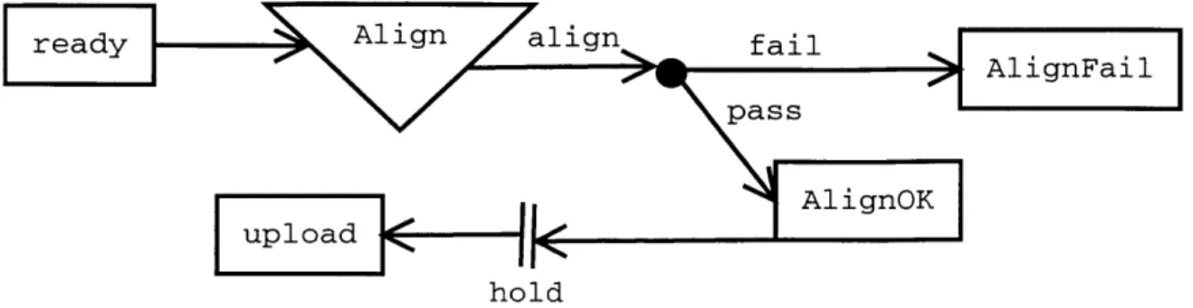
is data provided to the workflow system [3]. Figure 2-1 shows an example of the high level graphical language.
ready Align alinfi
readylign ailAlignFail
pass
uploadAig
K hold
Figure 2-1: An Example High Level Workflow Description This sample work-flow process definition uses a sub-workwork-flow and scheduling. The square boxes repre-sent simple States. The triangle reprerepre-sents a call to another workflow. The entire sub-workflow is executed as a single Step and its terminal State determines the Re-sult of that Step. If the alignment process has failed, the Material is moved to the AlignFail State. The parallel lines indicate that Materials will be held until some scheduling criteria is met.
User Code Interface
To enact the workflow, the developer must provide code to implement the specific functionality of the system. This code implements (in the case of computational steps) or represents (in the case of physical work) the actions of the process. Our system must provide a simple interface for user code and must encourage the development of reusable code.
The system combines the workflow process description and the provided code into the implementation of the workflow process. For each transition in the workflow graph, the system calls the appropriate user code for the step or accepts input from an external program. Having performed this step, the system adds the resulting Event to the Material's History, moves the Material to the correct State, and then proceeds to the next step in the process.
The interface between the system and the user code should be simple. The user code for Listeners receives the input Material and the previous Event in the process
but does not know its position in the process or the next step. In our design, the Material moving through the system is the basic unit of work and information. Con-sequently, each Step should require only that Material as input. The code for the Step should not require access to global state.
We do not allow the user code to specify the destination State for the Material; instead, we allow the code to return a Result that determines the Material's routing.
If we allowed the Listener to specify the next State, then all of the Listeners in a
process would be tied to each other, making reuse without modification difficult. For example, if class A referred to B which referred to C and we replaced C with Z, then we would need to replace or modify B and therefore A as well. By making the system map Results to States, we add a layer of indirection that allows and encourages user code to be more general than the process using it.
External programs that communicate with the system also need a simple interface for dispatching Events into the system. External programs need to dispatch Events to a particular State (generally the initial State of a process) and dispatch Events such that the appear to come from a particular State.
Workflow Parameterization
Workflows sometimes share the same structure (States and Event results) and code but differ in details. For example, a Step that checks the result of a laboratory test might need a higher quality threshold in one workflow than in another. Workflow Parameterization allows the developer to specify runtime parameters for the user code.
Reporting
The Workflow system should also provide facilities for report generation. With its standardized process representation and History recording, the system can generate many simple reports about the progress of Materials through the workflow
[6].
For example, the system can report how many Materials were processed by a Step during a specified time interval. Our design does not yet include a reporting system.Workflow Revisions
Workflows often change, either in the structure of the process being implemented or in the details of the Steps performed. A successful Workflow system needs to handle changes or revisions in the workflow in a convenient manner [7]. Chapter 4 discusses Workflow revisions in detail.
2.3
System Components
We now discuss the major components of our design.
" A language to describe Workflows at a high level. " A language to describe Workflows at a low level.
* A tool to translate the high level language into the low level language.
" A tool to design high level workflow descriptions.
" Classes to represent the Materials. To the Workflow system, these classes are
basically records (simple information containers).
" Classes to implement the work (Listeners). These classes take in a Material and
perform the appropriate work. Some of these will be single classes, while others will be external programs (not Listeners and not called by Listeners) that feed results to the system.
* Classes to record the work results (Events). These too are simple records pro-duced by the work classes and associated with Materials to form the Materials' History.
* A Workflow Engine that accepts a workflow description and the user code and enacts the process.
" A Storage Engine. The storage engine must store both the description of the
process, the process's run-time state, and serialized versions of the Materials and Events.
2.3.1
Workflow Description
Our Workflow Management System uses two levels of process description. At the high level, a GUI that presents the workflow as a graph to show how Steps fit together. However, a high level description might be a complicated entity with sub-workflows, parallel processes, dependencies, scheduling, and chaining. Such complexity would be difficult to handle in the actual Workflow Engine because of the variety and scope of features needed; the number of potential interactions between features might make testing the Engine difficult [5]. Furthermore, adding a new feature would require mod-ifying the core engine rather than a separate, peripheral component. Consequently, we have decided to use two levels of workflow description. The designer and users of the system use the GUI to create a high level description that can include all of the previously mentioned features. The high level workflow is translated into a lower level workflow description that is simple to implement.
Translation promotes extensibility by providing a well defined means to add fea-tures to the system without knowledge of the system's internals or modifications to the existing code. Furthermore, by implementing each feature as a separate set of filters, we provide clear boundaries between each feature and the core engine. These boundaries encourage modular implementations of the features. In particular, we want to avoid a complicated engine implementation in which the various features depend on each other.
High Level
The simplest workflow is a linear progression of Steps. Our high level description language includes a variety of features that can add complexity:
* Branches. Materials come to a fork in the process and can follow one route or another. In most cases, the branch selection algorithm is deterministic and based on the History of the Material. A simple case of Branching routes the Material to Step x+ 1 based only the Result of Step x (this is the default method of routing Materials from one State to another). In figure 2-1, there is a branch
after the Align sub-workflow based on the sub-workflow Result.
" Joins. Two paths through the system merge.
" Parallelization. Materials come to a fork in the process and proceed along both
paths in parallel. The paths could be paths through the same workflow or through sub workflows.
" Synchronization. Synchronization can take several forms. First, it can operate
as the inverse of parallel execution. Two paths join and a Material may not proceed past the synchronization point until it has completed both paths. In the second form, a Material might need to progress through two workflows A and B in parallel and the execution of the Steps of A and the Steps of B must be coordinated. For example, the third Step of B must happen at the same times as the fourth Step of A.
" Sub-Workflow. A Step in one workflow is another workflow.
" Chaining. Materials move through workflow A and then through workflow B
(but do not return to A, as they would if B were a sub-workflow).
" Timing and Scheduling. A workflow might have timing constraints that prevent
Materials from moving too fast, send notices if they move too slowly, or process Materials on some schedule. For example, a certain computational Step should only be run at night when the relevant machines are unused by interactive jobs.
Low Level
Our low level description does not directly implement most of the features available in the high level description. Instead, we use a very simple representation of the process. The description consists of a set of States and a set of Transitions. Each State corresponds to one set of actions. Each State contains one Transition object that maps the Result of the State's actions to the next State.
2.3.2
Translation
Since the low level description object cannot represent all of the desired high level features, the user interface translates the high level description into a low level work-flow description. System-provided Listeners implement various features in the high level description. To the Workflow Engine, these Listeners are no different than the Listeners provided by the developer. However, the translation system provides them to implement the high level features. For example, chained workflows can be imple-mented as two separate workflows. The translator adds a Listener to the terminal State of the first workflow that puts the Materials it sees into the second workflow.
2.3.3
User Interface
The user interface resembles a graph drawing program to allow the user to specify the structure and parameters of a process. When the user has specified the process structure, the UI deposits a WorkflowDescription object into the persistent storage using the Storage component (section 2.3.6). The GUI accepts dynamically provided pluggable widgets for use in workflow design. Each such widget represents one Step that can be added to a workflow and consists of :
" A factory to produce whatever objects represent States in the UI's
representa-tion of the workflow process.
" A filter that maps an instance of the workflow process representation to another
instance of the workflow process representation, replacing high-level features with the low-level equivalent.
" Optionally, icons or renderers for use in graphical interfaces.
2.3.4
User Code
Users provide three types of code. Listeners implement the actions in the workflow. Listeners must provide a method that accepts an Event and a Material and performs the action. Our design does not force Events and Materials to provide any methods
to the system as these objects are records for the process-specific data required by and produced by the Listeners.
2.3.5
Workflow Engine
The Workflow Engine provides run-time support for the process. When executed, the engine first obtains a workflow description. Our implementation accepts command line parameters to specify the name and version of a workflow that is to be retrieved using the Workflow Storage component (section 2.3.6). The engine then instantiate Listener objects for the States or some subset thereof. One might wish to instantiate only a subset of Listeners such that particular Steps are run on a particular machine or to better distribute the load from computationally intensive Steps.
Having completed its initialization, the engine accepts Events from Listeners and external programs, passing those Events to the appropriate Listeners. While passing Events, the engine updates the State and History of Materials (using the Workflow Storage).
Public Interface
To the developer, the Workflow Engine is relatively simple. It can be configured by providing a low-level description of the process and Listeners. Our implementation accepts command line parameters to specify a process name and the information needed to connect to SQL and JMS servers (see chapter 3 for more information). We do not provide a Java interface that can invoke the engine.
Our design specifies a minimal Java interface to the Workflow Engine for dispatch-ing Materials to the Engine. This interfaces provides two methods:
1. Dispatch an Event to a State : allows an external program to send an Event to
a particular State for processing. Only programs that dispatch Materials to the initial State of a Workflow should use this feature. External programs should generally not dispatch Events directly to the non-initial States of a workflow. For an external program to know which to which State an Event should be
dispatched, the program would need to know the workflow structure. While this is possible (as we provide a means to retrieve workflow definitions), most programs should leave Material routing to the system to ensure that the routing is performed correctly (in case other work is done in conjunction with routing). 2. Dispatch an Event from a State : allows an external program to send an Event that is to be dispatched as if it were from the specified State. This can be used with any non-terminal State in the system. It will be used primarily by programs that process Materials in States that do not create a new Event.
Failure Characteristics
Any engine implementation must have well defined failure and reliability character-istics. When running, the engine passes Events from one State to another. Clearly any implementation that drops Events is unacceptable as users will be unhappy when workflow instances disappear because Events were lost. If the Engine software crashes or is halted by a system or network failure, we need to know what happened to any active Events. It may be acceptable in this situation to simply inform a user that there was an error with the messages and require handling outside the system. We consider this reliable as long as all such cases are reported. In general, however, we expect that the system must reliably and properly deliver all messages.
In addition to handling failures of message delivery, the engine software must be able to handle Listener failures. If a Listener fails by throwing an Exception, then the system has several options:
" Ignore the problem. If an active Listener fails, then the system loses track of
the Material.
" Log the error but otherwise ignore the problem. The users of the system are
responsible for cleaning up any problems.
" Retry the Listener. While this might be useful for transient errors, there is no
* Stop. Stop processing the Material and notify the users or administrator.
Our system implements the last behavior. If a Listener fails, the system stops pro-cessing the Material and puts it aside for later handling by the system's users or administrator. We considered using the Retry behavior in some circumstances. If the designer of a workflow process could mark Listeners as idempotent, then the system could automatically retry those Steps up to some maximum number of times. We chose not to implement this behavior as it adds complexity but does not completely solve the problem as not all Listeners can be safely retried.
2.3.6
Workflow Storage
The first function of the workflow storage is to persistently store Workflow description objects. The second function is to store the run-time state of the system, namely the State and History of Materials. Finally, the storage component allows access to the current State and History of the Materials.
Splitting the Workflow Storage from the Workflow Engine accomplishes several goals. First, it accurately reflects the purposes of the two components. It seems slightly unnatural that the Workflow Engine, a run-time construct, should be queried for Material History or process descriptions. More importantly, it separates the im-plementation of the two components, allowing one to be replaced or modified inde-pendently of the other.
The Workflow Storage component records Material History and State. A Material is in zero or one States in any workflow. When a Material moves to a new State, the system removes the Material from the old State. When the Workflow Engine uses the Workflow Storage, the standard pattern is to move the Material from one State to another while adding an entry to the History; the Workflow Storage component should support this as a single atomic operation. History is an append-only list of the Events that have been associated with the Material'.
'Ideally, it is append only. In reality, entries in the History may be deleted or modified to correct software or laboratory errors.
State and History Reporting
The Workflow Engine is the primary writer to the Workflow Storage. However, any software interested in the workflow may read from the Workflow Storage to observe the current workflow status or to examine a Material's History. Our Workflow Storage provides methods to
" Get a Material's State in a workflow (or all workflows).
* Get a Material's History (a list of Events) in a workflow (or all workflows). * Get all Materials in a workflow that are in a certain State.
" Get all Materials of a certain type that are in a certain State.
" Get all Materials that have been associated with a certain Event. or type of
Event.
" Get all Materials that have been associated with a certain type of Event with
a certain Result.
We have not written a front-end to the reporting system to present this data to a user.
Users of the system will undoubtably want to perform more complex queries that combine the above mentioned criteria or that involve properties of the Materials and Events. Since our workflow system does not specify the persistence mechanism for Events and Materials, we cannot rely on its implementation and therefore have no way to query fields of these persistent objects. This presents no difficulties for the runtime components of the system but precludes a generic reporting infrastructure. We anticipate that a generic reporting infrastructure will be written to support a generic object storage facility, but have not implemented such a tool.
High level description kflow Work 3lation Classes vel Material Classes low le descript Workflow Event Engine Classes runtime data Storage Engine history information Reporting Engine
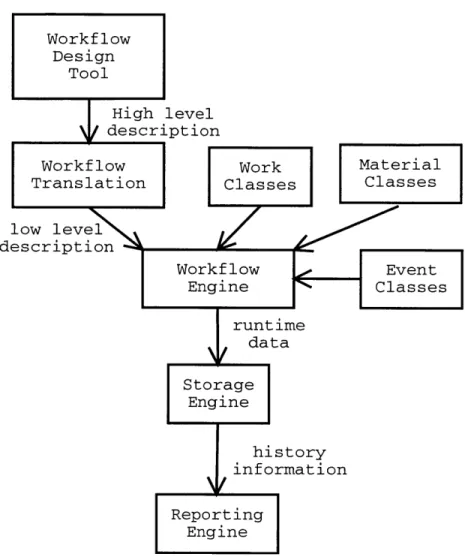
Figure 2-2: Major System Components The user creates a high level description of the process with the Workflow design tool (the GUI). The GUI's translation com-ponent translates the high level description into a low level description that uses only simple primitives of Listeners, Results, and States to process Materials. The user provides the low level description and code to implement the Steps (work classes), Materials, and Events to the Workflow Engine, which enacts the process.
The Workflow Engine relies on the Storage Engine to maintain the State and History data. A reporting component, which we have not implemented, might read the His-tory data from the Storage Engine to generate reports about workflow throughput or status. Workflow Design Tool Wor Tran Ion
Chapter 3
System Implementation
Our Workflow System's implementation consists of components (process design tool, storage, and runtime engine) that interact through a few simple interfaces. The Workflow Description Classes lie at the center of our system. These objects describe a workflow process and all other components depend upon them. The Base Runtime Classes represent the dynamic objects (Materials, Events, Listeners) used by the other system components. The remaining components (storage component, a runtime engine, and a user interface) all interact through the WorkflowDescription classes and the Base Runtime classes. Consequently, the interfaces and implementations of the peripheral components can be changed with minimal effect on the remainder of the system.
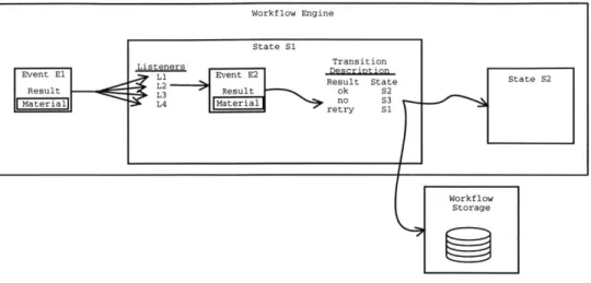
Figure 3-1 shows the flow of data through the Workflow Engine.
3.1
Workflow Description Classes
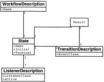
The low level workflow description language's components are shown in figure 3-2. We ignore the high level description system here since many high level description languages could be translated into our single low level language and because only the user interface relies on the high level description.
Workflow Engine
State S1
Event El i Event E2 L
erial
Result State State S2 ResultL2t
MaeralL4 Maeilno S3
Workf low Storage
Figure 3-1: Runtime Dataflow in the Workflow Engine This figure illustrates the flow of data for one Step in a process. The Engine has already read a process description and created its runtime representation of the States in the process. At left is the incoming Event, El, which contains a Material. The Engine has used the Result of El to route it to State S1. At S1, the system invokes each Listener on the Event (and therefore on the Material). One Listener may produce a new Event, E2. The Engine uses the Transition Description associated with S1 to map E2's Result to the next State. For example, a Result of "ok" maps to State S2. Before dispatching
E2 to S2, the Engine uses the Workflow Storage to associate E2 with the Material
and to associate the Material with State S2.
WorkflowDescription WorkflowDescription is the top level object to describe a process. A WorkflowDescription has a Name attribute and contains a collection of States.
State The State class corresponds directly to the concept of a State as a queue of Materials waiting for some action or as a label to describe a Material's sta-tus in the process. A State's Name attribute must be unique among all States in the WorkflowDescription. The State also has boolean Initial and Terminal to indicate whether the State is the first or last in the workflow. A State con-tains a reference to a single TransitionDescription describing the path of Ma-terials that have been processed by the State. Finally, a State contains a set of ListenerDescriptions, at most one of which may describe an ActiveListener (see section 3.2.4). A ListenerDescription specifies the Name of a class to execute when
WorkflowDescription +Name *
State
+Name +Initial +Terminal 1 I 'TransitionDescription +EventClass ListenerDescription +ListenerClass +activeFigure 3-2: UML Diagram of the low-level Workflow description classes. A WorkflowDescription is a collection of State objects with a Name. The WorkflowDe-scription may contain any number of States, but a State must be contained by exactly one WorfklowDescription. A State has a name and boolean attributes to indicate if it is an initial or terminal State in the process. A State may contain any number of ListenerDescription, each of which describes one Listener to be run on Materials in that State. At most one of the Listeners at the State may be marked "active" to indicate that it creates a new Event when invoked.
A non-terminal State must contain one TransitionDescription. Terminal States have
no TransitionDescription. The TransitionDescription indicates the class of the Event object that Listeners at the State may produce. The TransitionDescription also maps the Result of the Events produced to another State.
a Material arrives in this State. A ListenerDescription also contains a set of pa-rameters that can modify the behavior of the Listener code on a per-workflow basis.
A State does not contain the actual Listeners; this would require having working
code for those classes during process design, which may happen before the Listeners have been written.
TransitionDescription A TransitionDescription describes the paths from one State to other States. The TransitionDescription specifies the Class of the Event that will be passed from the SourceState to the next State. All Events contain a
Result, a Material, and a Date. The TransitionDescription maps each Result to the next State.
3.2
Base Runtime classes
All runtime components share the Base Runtime classes. Materials represent the physical or computational objects that the system processes. Events record the results of the work performed by Listeners on these Materials.
3.2.1
Materials
Material classes implement the Material interface. A Material must have
* A unique numeric identifier. The Workflow system uses the identifier internally to track Materials. To keep the History and State for a Material, the system must have access to some globally unique identifier for that Material.
" A creation date. The creation date is primarily useful to end-users or to devel-opers who are debugging the workflow.
Classes that implement the Material interface may have as many other fields as the developer sees fit to represent the physical or computational object.
3.2.2
Events
Events implement the Event interface to record the actions in the Workflow. Every Event has
* A unique numeric identifier. The system uses the identifier to associate the Event with the relevant Materials.
" A Date on which the action took place. In some cases, a single date is insufficient
to describe an Event (e.g. the starting data and ending date of a long running computational process might differ by many days); we use a single date now for
simplicity. Event classes are free to define attributes to allow more temporal information to be stored.
e The Material upon which the action was taken.
* The Result of the action. This is a simple summary (represented as a string) of the outcome or Result such as OK, PRESENT, or RETRY.
Classes that implement the Event interface may have as many other fields as the developer sees fit to represent the physical or computational work they represent.
3.2.3 Storable
Materials and Events share three common behaviors in the context of a workflow system. First, both are passed as inputs and outputs to and from the code that implements the actual work of the process. This work may be done across time and machines. Second, relationships between both types of objects are stored by the workflow system to indicate the History and state of the system. Third, both Events and Materials are assumed to have fields of interest to the user but which the generic system components can ignore.
To recognize these similarities between Events and Materials, both interfaces in-herit from the Storable interface. Storable objects provide two behaviors. First, each Storable object has a unique numeric identifier that the workflow system can use to track the object. Second, a Storable object supports the store and get operations that save its fields to some persistent store and retrieve those fields.
To the runtime components of the workflow system, the methods used to gener-ate unique identifiers and to provide object persistence are largely irrelevant. The system's Engine calls the store method at appropriate times to ensure that objects are stored However, the system does not attempt to access the stored data nor does it use the get method.
3.2.4
Listeners
The work classes implement the actual work of the Workflow. Since our Workflow system is written in Java, we attempt to express their role in standard Java terms. Hence, we call these Listeners attached to a State. The Events received indicate that a Material has entered the State. Implementing Listener, these classes provide an onEvent method that receives the Event generated by the previous Step/Action in the workflow. This input Event is generally the output of another Listener (the one attached to the previous State) or the output of an external program. From the Event, the Listener extracts the Material to be processed.
The decision to define onEvent as taking an Event as input has several important characteristics. First, this approach seems natural to implement; whatever system code for passes Events to Listeners should clearly not depend on the concrete type of the Event. Instead, it should handle any implementation of Event. A Listener does not know at compile time type what type of Event it will receive. While it would be trivial for code to use Java's instanceof operator or a reflection method to determine this information at run-time; however, our design must encourage the development of work classes that are independent (to the greatest degree possible) of the type of Event received and therefore of the preceding Listeners in the workflow. We hope that this independence will make the code written more general such that it can be easily reused in other workflows.
Our system provides a mechanism to parameterize the behavior of the work classes. For each Listener attached to a State, the process designer may provide a list of properties. At run-time, the code performing the action has access to these properties and may modify its behavior accordingly.
We have divided Listeners into two types. The first type of Listener receives Events, but has no effect on the system. This type of Listener is passive (from the system's view). The second type of Listener is active; it receives Events, processes Materials, and then returns a new Event describing that work to the system. A State can have only one Active Listener associated with it, whereas any number of Passive
Listeners may exist for a State. Multiple active Listeners would allow multiple results to be returned, each potentially routing the Material to a different State.
Passive Listeners
Passive Listeners can implement many key functions of the system even though they cannot directly return an Event. A simple example is an observer for an error State that emails interested parties to inform them that the processing of a Material has failed. Passive Listeners might also append items to the work list of a user. More complicated passive Listeners might interact with external databases or programs.
Active Listeners
Active Listeners provide a method to return an Event to the system. An Active Listener can represent any work that can be performed on demand. In general, any purely-computational Step meets this criteria.
External Programs
Not all work is performed by Listeners attached to States. The inherent restriction of a Listener is that it be able to perform its work upon demand- when an Event is passed to it. In many cases, a Listener would have to block until some laboratory or "real world" work is done. Other workflow systems have included protocols, often quite complex, to interact with asynchronous processes or entities (e.g., people).
In our system, we took a simpler approach. Rather than block, the Listeners do whatever work can be performed on demand but return no new Event to the system. Instead, some external program will provide the Event to the system when the work is complete. For example, the passive Listeners at a State might add an item to a work list to indicate laboratory work that needs to be done by a user of the system. The user would run a data entry program that dispatches the relevant Events back to the system. Section 3.6 discusses other uses of external programs in more detail.
3.3
Workflow Storage Component
The storage component provides persistent storage of process definitions, stores the runtime status of process instances, and records the History of process instances. The current implementation of the Storage component uses an SQL database as a persistent store. All database interaction goes through the Java JDBC interfaces to minimize the quantity of RDBMS-specific code. The database schema for our Oracle implementation of the storage component is found in appendix A.
The Storage Component presents a public interface to retrieve process definitions and to query the current State and History of a Workflow Instance.
3.3.1
Process Definition
To store a process definition, the system needs to serialize the objects described in figure 3-2. The tables Workflow, WFState, StateListener, and TransitionDesc store one row per corresponding objects. Properties is a supplementary table to store the properties for Listeners. TransitionResult corresponds to the mapping from a TransitionDescription to States and stores one row per result.
The Class table maps a class name to an internal id. This is used for process definition storage to record the Listeners attached to a State and to record the type of Event expected at a TransitionDescription.
3.3.2
Process Instance Status
The runtime tables store the status of the process instances. StateMap maps a [Ma-terial, Workflow] pair to a State. No Material can be mapped to multiple States in the same workflow.
ClassMap maps the identifier of Storable objects to their class. This table is updated at runtime as Materials are associated with States. The purpose of the in-formation is to be able to recreate objects as necessary. For example, a program might wish to retrieve all of the Materials in a specified State to perform some pro-cessing. The system fulfills this request by examining the StateMap to obtain the
object identifiers for all of the Materials in that State. It can then determine the class of each object and use Java's reflection methods to instantiate an object of that class, providing the identifier as the single argument to the constructor. The exter-nal program could then call the object's get method to retrieve the other fields as necessary.
The append-only table HistoryMap associates Events with Materials to record the History of the Material. All writing to this table occurs while the process is active.
The WorkflowInstance and InstanceMaterialMap tables are not used by the ba-sic workflow implementation. Their purpose will be discussed as part of the versioning implementation (chapter 4).
3.3.3
Process History
Process History, as mentioned, is stored in the HistoryMap table. This table as-sociates a Material with an Event. For efficiency, the Result, Date, and Workflow identifier are also stored. This allows the system to generate statistics about the num-ber of Materials processed in some time frame or the numnum-ber of Events containing Result.
3.3.4
RDBMS Dependencies
The dependencies on the RDBMS implementation are limited to
" The schema. Different database systems have slightly different Data Definition
Languages. Consequently, we must write a schema for each database system. The correct schema must be used when the database is prepared for use with the workflow system. After this one-time event, the different schemas are not relevant.
" The database connection. Different database systems have slight differences in
the code required to make a connection to the database. This problem can be handled in several ways by encapsulating the database dependency in a single class or method, thus insulating all but a small part of the system.