Optimised robot-based system for the
exploration of elastic joint properties
\
M. Frey I R. Burgkart 2 F. Regenfelder 2 R. Riener 3"* 1Institute of Automatic Control Engineering, Technische Universitfit M~nchen, Germany 2Clinic for Orthopaedics & Sport Orthopaedics, Technische Universit~t M~nchen, Germany 3Automatic Control Laboratory, Swiss Federal Institute of Technology (ETH) Zurich, Switzerland
A b s t r a c t - - N u m e r o u s publications provide measured biomechanical data relating to synovial joints. However, in general, they do not reflect the non-linear elastic j o i n t properties in detail or do not consider all degrees of freedom (DOF), or the quantity of data is sparse. To perform more comprehensive, extended measurements of elastic j o i n t properties, an optimised robot-based approach was developed. The basis was an industrial, high-precision robot that was capable of applying loads to the j o i n t and measuring the j o i n t displacement in 6 DOF. The system was equipped with novel, custom-made control hardware. In contrast to the c o m m o n l y used sampling rates that are b e l o w 100 Hz, a rate of 4 kHz was realised for each DOF. This made it possible to i m p l e m e n t advanced, h i g h l y dynamic, quasi-continuous closed-loop controllers. Thus oscillations of the robot were avoided, and measurements were speeded up. The stiffness of the entire system was greater than 4 4 k N m 1 and 2 2 N m d e g 1, and the m a x i m u m difference between two successive measurements was less than O.5deg. A sophisticated CT-based referencing routine facilitated the matching of kinematic data with the individual a n a t o m y of the tested joint. The detailed detection of the elastic varus-valgus properties of a human knee j o i n t is described, and the need for high spatial resolution is demonstrated.
Keywords--Biomechanics, Knee kinematics, Robotics, Joint stiffness, Elastic j o i n t properties
Med. Biol. Eng. Comput., 2004, 42, 674-678
1 Introduction
ONE METHOD to determine the elastic properties of human joints as a function of displacement is to apply load while the resulting displacement is recorded. Several authors have measured such data in vivo (MOORE et al., 1976; RIENER and
EDRICH,
1999; TORZILLI et al., 1981). The main problem has been the moving soft tissue between the fixing of the measurement apparatus and the bones, which made precise measurements difficult to obtain. Furthermore, measurements of both an intact and an injured knee joint is only possible by accident for a single subject, as it is not justifiable to cause injury to a healthy person for research reasons. Hence, many groups have used human cadaver knee joints for biomechanical data acquisition.Early measurement systems used different devices to apply load in different degrees of freedom (DOF) in a hand-operated manner (MARKOLF et al., 1976) or with weights (BLANKEVOORT et al.,
1988). The load was measured with strain gauges, and the position was measured with externally fixed potentiometers (MA~KOLV et al., 1976) or with a camera system
(BLACHARSKI
e t al., 1975). inCorrespondence should be addressed to Martin Frey; emaih martin'frey@paralab'balgrist'ch
*Also with Spinal Cord Injury Center, Universffy Hospital Balgrist, Zurich, Switzerland
Paper received 23 December 2003 and in final form 26 April 2004
MBEC online number: 20043913
© IFMBE: 2004 674
the meantime, more advanced, partly automated set-ups have been developed. Single DOF were driven by hydraulic (PIZlALI and RASTEGAR, 1977) or electric (BEERS et al., 1990; DURSELEN et al.,
1995; FUKUBAYASHI et al., 1982) actuators. However, these systems were limited in flexibility or in the number of DOF that could be actuated or measured. Furthelmore, it was hard to guarantee that there were no constrained loads applied to the joint. FUJIE et al. (1993) and W o o et al. (2000) used an industrial robot* in combination with a universal force torque sensor (FTS)
(FUJIE
e t al., 1995) to measure elastic joint properties, in the meantime, other working groups picked up this idea. NEMECet al. (2000) used a Riko 106 robot to test the kinematics of
synovial joints. HURSCHLER et al. (2001) used a KUKA KR 15 robot to simulate arm forces while testing the shoulder joint. These set-ups were fully automated and able to move a joint and measure the load in 6 DOF simultaneously. Unfortunately, even modern industrial robots do not have a powerful control unit. Thus the sampling rate is very low (e.g. Stfiubli RX 90-B, year of manufacture 2001, maximum sampling rate 62.5Hz). As a result, oscillations occur during measurement of quite stiff joints, or if the measurements take a long time.
The aim of this work was to develop an optimised robot based system that would enable fast, accurate and comprehensive measurements of elastic joint properties. For this purpose, new control hardware and software was developed. No oscillations
*Unimate Puma Model 762
should occur during the measurements, and various measure- ment protocols have been be realised.
2 Material and m e t h o d s 2.1 Set-up
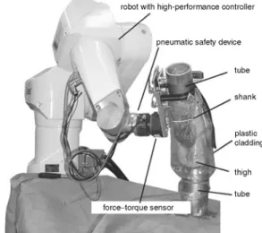
The key element of the experimental set-up was an industrial, high-precision robot t, which is known as orto Marquet's surgical robot 'Caspar'. it is able to apply static forces of up to 120 N and torques of up to 10Nm. it is equipped with a pneumatic safety device ~ and a 6 DOF force torque sensor**.
The adjacent bones of a human cadaver joint were osteoto- raised 20 cm above and below the knee joint line. They were embedded into aluminium tubes with methylmethacrylat, and each bone was additionally fixed with three screws. Plastic cladding enclosed the cadaver to avoid dehydration. The tube with the thigh was mounted on the robot base (RB) (Fig. 1). The shank was attached to a plate that could be fixed to or dismantled from the FTS within seconds by quick-release skewers. The position of the cadaver leg relative to the robot was chosen such that the measurements were not constrained by singular constel- lations, which occur if at least two robot joints are aligned. This would have resulted in a reduction in the number of DOF, thus restricting the robot's mobility. The ethics committee of the university approved the study using human cadavers.
2.2 Control hardware
The robot was equipped with a novel, real-time, Linux-based controller developed in our group
(HOOGEN
et al., 2002). it runs on a Pentium IV with 1.9 GHz. The interface to the robot was realised with adequate PCI cards for the FTS signal, for the signals of the robot joint encoders and for the output signals that were used to control the motor currents of the robot joints. Thus the sampling rate could be increased by a factor of 64 up to 4 kHz for each channel. This enabled us to implement highly dynamic, quasi-continuous control strategies.2.3 Co-ordinate systems
The world co-ordinate system (CS) i 0 (index 0) was located in the RB, and the end effector (EE) CS IEE (index EE) was locked at the end of the robot arm (Fig. 2). The shank CS i s and the thigh CS i T were fixed to the cadaver. They were matched in full extension ( i s = iT). The choice of the co-ordinate system was based on the definition of GROOD and SUNTAY (1983), recommended by the ISB (Wu and
CAVANAGH,
1995). Modifications were made to obtain an orthogonal CS, and the descriptions of the axes were changed.2.4 Referencing routine, displacement and load calculation For referencing, the thigh and the shank were fixed, at full
B extension, by an external clamp. The pose of the shank CS Ts
B
and of the thigh CS TTwith respect to the CT base (index B) were estimated by an experienced orthopaedic surgeon in a segmented and 3D reconstructed CT scan of the cadaver joint. Three artificial landmarks at the tubes clearly defined the reference CS eTR with respect to the CT base. They were also located by a measuring device that was mounted on the robot. This resulted in the pose of
0
the reference CS with respect to the robot base TR. Thus the
0 0 R B 0 B 1 B
poses of the thigh CS TT= TR T , . TT= TR ( TR)- " TT
0 0 /Y 1 B ,
and of the initial shank CS Ts(to) = TR. ( TR)- . Ts with respect to the RB were clearly determined.
tSt~ubli RX90-B, St~ubli AG, Switzerland ~IPR GmbH, G e r m a n y
**JR3 Inc., USA
robot with high-performance controller
/
pneumatic safety device / • ~ ' /.~,, ~ ~ ) - - tube ~" I ~ ' ~ . .... • / ~ ' : ~ ~ shank
t /
/
thigh
] ~ f - ? ~ ~ / . ~ " ~ tube Jk ~ '! " f . . . . torqu .. . . I ~ " J H r , "- - iVi/, / ~.Fig. 1 Robot-based system
Now the robot was attached to the shank, and the initial EE position °TEE (to) with respect to the RB was calculated from the robot kinematics. Then, the clamp fixing the aluminium tubes was dismantled. The pose of the shank °Ts with respect to the RB was given by °Ts= °TEE. EETo(to)" °Ts{to)= °TEE" (0TEE(t0))--1-°Ts(to) when the robot was moved. The actual displacement of the knee joint rTs = rTo °Ts= (°Tr)-i - °Ts was characterised by the pose of the shank relative to the thigh.
The displacement representation rTs was transformed into a medical, non-orthogonal representation. The medical co- ordinates (MCs) were described by the FE rotation about, and the ML translation along, the x-axis of Zr. Then the VV rotation was performed about, and the AP translation was performed along, the actual flexed/-axis. Finally, the IE rotation and the PD translation were executed about and along the actual flexed and VV rotated z"-axis.
The FTS was located at the robot EE. According to the pose of
T T 0 0 1
the EE with respect to the thigh TEE = TO" TEE = ( TT)- " °TEE the f0rcefEE is transformed to I T byfT = TREE "fEE and the torque tEE is transformed by t r = TREE. tEE . (tEE+ I r i ~ E E X fEE). The matrix TREE was the rotation matrix of TTEE , and ZTI~EE was the vector from the centre of I T to the centre 0fiEE. Then, the forces and torques were transformed to MCs. Now, load and displacement were represented in MCs that were used for control.
2.5 Control strategy
it is possible to measure elastic joint properties in two principal ways: first, by moving the leg to a certain position and measuring the produced load, and, secondly, by applying a predefined load and measuring the caused displacement.
Fig. 2
E E T s , ~ \ S Z
i "? S
" / q ' \ . . . . T
I
[-gT]-
Fig. 3 Closed-loop position controller
The first method is optimum to measure with predefined position step width or regions with very low elasticity, e.g. the internal-external rotation DOF near zero load condition. The leg would rise to a large internal or external angle i f a small, perhaps parasitic load were applied. Thus, it m a y be necessary to fix the joint to a certain position. Therefore a closed-loop position control was required, it was realised b y a speed limited, closed-loop integral controller in MCs with a quite high gain P~ and a subsidiary robot joint-based state-space position-velocity control (Fig. 3). The transformation between robot joint space q and the MC x was made with the state-dependent, non-linear Jacobean matrix Jmed that was calculated from the robot kinematics and the
transfolmations mentioned in Section 2.4.
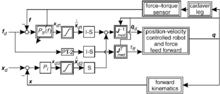
The second method is used to avoid constrained loads in single DOF or to measure with a predefined load step width. This method requires a closed-loop force control. The actual l o a d f and the desired loadfd, both given in MCs, were compared. The difference was the input for an adaptive integral controller and the subsidiary robot joint-based position-velocity control mentioned above (Fig. 4). The gain o f the outer control loop was on-line adapted as a function o f the actual force. Additionally, there was a force feed-forward that was smoothed b y a second-order filter (PT-2).
As there are large variations in the elastic properties among the single DOF o f the knee joint, some DOF have to be position- controlled others and have to be load-controlled. This was realised b y a hybrid closed-loop, load-position control (Fig. 5). it was a combination o f the position controller in Fig. 3 and the force controller in Fig. 4. The choice o f position or load control was made b y the diagonal selection matrix S (S 0. = 0, if i 5&j).
The signal o f the position control loop was processed to the inner loop ifSii = 1. Otherwise, ifSii = 0, the output o f the outer load
control loop was passed to the inner loop. Thus each DOF could be either load or position controlled.
2.6 Accuracy
The relative position error in Cartesian space was specified to be lower than 0.02mm. The stiffness o f the set-up, including mounting device and force sensor, was measured. Therefore an aluminium tube was fixed to the RB, and the robot was attached to the tube. Load was applied to the tube, and the displacement was recorded. The resulting transverse stiffness
Fig. 4 Closed-loop load controller
676 forcetorque I I II s e n s o r i1~11 leg IC f x I position-velocity dl Xdl qd
I r ~ iiJ i I I I ~ ml~J~ I I controlled robot II q
I " ~ I ~ T II and force II
I ~ 1 ~ I feed forward II
kinematics Ir
Fig. 5 Hybrid closed-loop load-position controller
was between 4 4 k N m -1 and 1 8 8 k N m -1, depending on the robot constellation. The rotary stiffness was higher than 22 N m d e g - 1.
2.7 Protocol
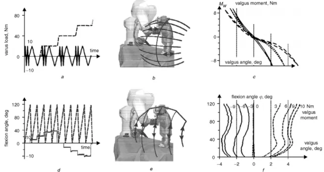
As an example, the protocol o f measuring the elastic varus- valgus properties as a function o f the flexion angle is presented. The flexion DOF was position controlled, and the varus DOF was load controlled. While one or the other was varied, the other DOF was fixed to a certain value. The fixed DOF could be the flexion angle (top o f Fig. 6) or the varus moment (bottom o f Fig. 6). Varus load varied between - 1 0 N m and 10Nm, and the flexion angle varied between hyperextension ( - 5 °) and fifll flexion (120 °). All translatory DOF were zero force controlled to avoid reactive forces. The internal-external rotation DOF was fixed to the zero rotation angle that was recorded d u t n g initialisation o f the cadaver.
The movements with fixed flexion DOF were comparable with the execution o f a varus-valgus stress test
(RITCHIE
e t al., 1994). The measurements resulted in a hysteresis curve for each flexion angle (Fig. 6c). The measurements with fixed valgus loads resulted in level curves o f the elastic valgus properties (Fig. 6J). Fig. 6fdisplays the flexion-dependent valgus displace- ment at a constant valgus load.3 Results
After testing and optimising o f the experimental set-up with five animal knee joints, the elastic characteristics o f three fresh frozen human knee joints were analysed. Therefore individual properties o f the intact, as well as the pathological, knee joint were determined in 6 DOF and with high spatial resolution, to be applicable for the Munich knee joint simtflator (RIENER et al.,
2004; FREY et al., 2003a).
As an example, the detection o f the passive elastic varus- valgus properties as a function o f the knee flexion angle is described. Approximately 30 min were required to run the basic protocol. Both the displacement and load data were recorded in 6 DOF at flexion angles o f - 5 °, 0 °, 10 °, 20 °, 30 °, 40 °, 60 °, 80 °, 100 ° and 120 °. At each flexion angle, the varus load was increased up to 10 Nm, then decreased to - 10 N m and again increased up to 0 N m in steps o f 1 Nm. The setting o f the protocol and two cycles o f preconditioning at each flexion angle were also included within this time frame.
Regardless o f the relative accuracy o f the used robot, the point o f interest is the repeatability o f the measurements performed. To analyse this aspect, the protocol mentioned above was completed twice with varus load increments o f 0.25 N m and 0.5 N m (Fig. 7). in the first measurement, the robot EE was mounted medially o f the tibia, and, in the second measurement, it was mounted frontally. The m a x i m u m deflection between the two measurements was 0.25 ° at the m a x i m u m load o f 10Nm. Medical & Biological Engineering & Computing 2004, Vol. 42
80 40 f r
II Vll Vll Vll V "
10 a 8: 8 valgus moment, Nmi "%'~;2'
i i i i i • " ~ % i I I I N " valgu angle, eg o Fig. 6 120 I I I • 120 I II ii / , 1 I I .I tl "1 ,I |1 II ~i I I 80 " i ; l I I ; l El | ! 31 11 I I ! i , I • ! I = t I q t 80 o2 4 , 1 1 1 , 1 1 1 , j . l l l l l . l , I t | I . i I| I I I , i t | ~ | , I I I t i f , = ' 1 40 1.' I; /.i-l-~l: II I_I II ~ I H i# i! if t "~ R I 1~ | | i 4 0 % 1 0 0 d eflexion angle (?, deg i ~ 9 1 Y 6 \ 0 3,;
6!/'9//lO
Nm \ ~ ! \ ~ . / ~ / / valgus1) i / |
t / ],t m o m e n t t l i t t ~ , I/t(/ i(, /
',, " i~ II I b I I~l valgus | | t'i t r , " * / / ~ , f f angle, degi i
4 2 2 4
f
(a), (d) Measurement protocols and (c 9, (f) resulting curves. Protocol with fixed flexion angle is displayed on top," protocol with fixed varus load is displayed at bottom. (a) (---) Flexion angle, deg; (--) valgus moment, Nm. (c) Flexion angle." (--) Odeg; (---) 4deg; (--) lOOdeg;
This was in the same range as the error caused by the pose- dependent stiffness of the set-up.
For all cadaver legs, highly non-linear and non-symmetric characteristics of the elastic varus-valgus properties were measured. At flexion angles larger than 60 °, there was a sharp bend close to zero load (Fig. 7a). A possible explanation is that the lateral femur condyle lifts off the lateral tibia plateau when varus load is applied, as the lateral collateral ligament is relaxed at 80 ° of knee flexion
(BRANTIGNAN
and VOSHELL, 1941). During valgus load, the lateral femoral condyle is then in contact with the tibia plateau, with simultaneous tensioning of the medial collateral ligament. Thus the elastic stiffness increases with a high slope.The protocol was processed again, but with a spatial resolu- tion of 2 Nm. The measured points were interpolated with cubic splines. The resulting curve is almost symmetrical (Fig. 7b), as is reported by MARKOLF et al. (1976). Details such as the sharp bend in the varus-valgus characteristics are lost as a result of the low resolution.
4 D i s c u s s i o n
The following outstanding aspects of the presented robot- based set-up for the detection of passive elastic synovial joint properties should be emphasised.
8 -
4 -
0 -
- 4 -
-8-
h, valgus moment, Nm valgus moment, Nm
/ i nterpolation
~/ 1 ~ valgus angle, deg t, I--.1 . . % ....
valgus angle, deg
Fig. 7 Measurement of varus-valgus stiffhess. Flexion angle 80 °.
(~--~) Frontally attached," (o ... o) medially attached
First, the novel control hardware of the robot should bring benefits from all the advantages associated with the use of high-precision industrial robots. High position accuracy, a high degree of stiffness and the ability to move the EE in 6 DOF are applicable at a sampling rate increased by a factor of 50-100 up to 4 kHz.
Secondly, previous robot based set-ups have used sequential control strategies (FUIJE et al., 1993; RUDY et al., 1996). Within these strategies, the desired position is calculated by an outer loop and processed to a closed-loop position controller, if the desired position is reached, the next desired position is calcu- lated. Between two steps of the outer loop, it is not possible to interfere with the movement of the robot. Furthermore, the sampling rate of the outer loop is well below 100Hz. This causes stability problems during force control (LAURENCE, 1988; COLGATE and BROWN, 1994).
in contrast, the set-up presented uses a quasi-continuous closed-loop controller that has a time delay that is only 0.25 ms. Thus it behaves like a continuous controller that reacts to the applied force without appreciable delay. Because of the high speed of the new controller, it is possible to perform numerous measurements with a single cadaver and with high spatial resolution, in spite of the limited time due to the disaggregation of the cadaver. Furthermore, high spatial resolution facilitates the recognition of details, as shown in the results. Thus more accurate and even new insights into joint kinematics can be obtained when joints are analysed with high spatial resolution.
Thirdly, the sophisticated initialisation routine enables the cadaver leg to be matched with the joint CSs, which are defined in the 3D reconstructed CT data. This enables kinematics and anatomy to be aligned on-line during the measurements or afterwards, when the recorded data are analysed. Thus it is now possible to correlate changes in the anatomy, e.g. after an operation, with changes in the kinematics. This expands the capabilities to refining operative techniques and enables exact analyses of the physiological biomechanics and pathological changes.
Fourthly, the measurement protocol can be easily adapted to any application. No modification of the mechanical set-up is necessary, as the protocol is specified in the software, and both the control hardware and software are able to move the EE and to record the position and the load in 6 DeF.
The collected data form the basis on which to generate a comprehensive dynamic biomechanical model o f the intact and the A C L ruptured knee joint. The m o d e l describes the joint m o v e m e n t as a function o f the applied load during a physical examination with clinical knee joint tests.
Thus the set-up is designed to measure elastic joint properties under load conditions that usually occur during an examination o f the knee joint b y an orthopaedic surgeon (FREY et al., 2003a; b). A s the m a x i m u m p a y l o a d o f the robot is limited, it is not possible to simulate the loads that typically appear during standing and walking. However, the methods are transferable to any industrial robot with higher payload. Then, we must be aware o f the fact that the accuracy decreases with increasing payload, in this case, the presented control strategy becomes even more important, as stability problems increase with lower sensor accuracy and increasing measurement noise.
The use o f a 6 D O F industrial robot and o f a 6 D O F FTS in combination with novel control strategies, with a routine to match anatomy and biomechanics and with m o d e m tools for computer-based data analysis, will enhance the examination o f elastic joint properties.
Acknowledgments" The author w o u l d like to thank J. Hoogen, G. Schmidt, F. Freyberger, T. Pr611 and M. Buss for their assistance in this study.
This w o r k was supported b y the German Ministry for Education & Research within the project network on 'Virtual Orthopedic Reality (VOR)', project number 01 IR A15.
References
BERNS, G. S., HULL, M. L., and PATTERSON, H. A. (1990): 'Imple- mentation of a five degree of freedom automated system to determine knee flexibility in vitro', Trans. ASME, 112, pp. 392-400 BLACHARSKI, P. A., SOMERSET, J. H., and MURRAY, D. G. (1975): 'A three-dimensional study of the kinematics of the human knee',
J Biomech., 8, pp. 375-384
BLANKEVOORT, L., HUISKES, R., and DE LANGE, A. (1988): 'The envelope of passive knee joint motions', J Biomech., 21, pp. 705-720 BRANTIGNAN, O. C., and VOSHELL, A. E (1941): 'The mechanics of the ligaments and menisci of the knee joint', J. Bone Joint Surg., 13, pp. 44-66
COLGATE, J. E., and BROWN, J. M. (1994): 'Factors affecting the z-width o f a haptic display'. Proc. IEEE 1994 Int. Conf. Robotics & Automation, San Diego, CA, pp. 3205-3210
DURSELEN, L., CLAES, L., and KIEFER, U. (1995): The influence of muscle forces and external loads on cruciate ligament strain', Am. J.
Sports" Ned., 23, pp. 129-136
FREY, M., PR(3LL, T., RIENER, R., and BURGKART, R. (2003a): 'Making biomechanics sensible'. Proc. Workshop on Computer Simulation in Biomechanics (ISCSB), Sydney, Australia
FREY, M., PROLL, T., RIENER, R., and BURGKART, R. (2003b): 'Vazus- valgus stiffness model of the knee identified by a robot based approach'. Proc. Anniversary of International Society of Biome- chanics (ISB), Dunedin, New Zealand
FUJIE, H., MABUCHI, K., WOO, S. L.-Y., LIVESAY, G. A., ARAI, S., and TSUKAMOTO, Y. (1993): 'The use of robotics technology to study human joint kinematics: a new methodology', J Biomed. Eng., 115, pp. 211-217
FUJIE, H., LIVESAY, G. A., WOO, S. L-Y., KASHIWAGUCHI, S., and BLOMSTROM, G. (1995): 'The use of a universal force-moment sensor to determine in-situ forces in ligaments: a new methodo- logy', J. Biomed. Eng., 117, pp. 1-7
FUKUBAYASHI, T., TORZILLI, P. A., SHERMAN, M. E, and WARREN, R. E (1982): 'An in vitro biomechanical evaluation of anterior-posterior motion of the knee', J. Bone Joint Surg., 64-A, pp. 258-264 GROOD, E. S., and SUNTAY, W. J. (1983): 'A joint coordinate system for
clinical description of three-dimensional motions: application to the
knee', J Biomech. Eng., 105, pp. 136-144
HOOGEN, J., PONIKVAR, M., and SCHMIDT, G. (2002): 'A robotic haptic interface for kinaesthetic knee joint simulation'. Proc. 1 lth
678
Int. Workshop on Robotics in Alpe-Adria-Danube Region, Balatonfuret, Hungary
HURSCHLER, C., W1JLKER, N., WINDHAGEN, H., PLUMHOFF, P., and HELLMERS, N. (2001): 'Medially based anterior capsular shift of the glenohumeral joint-passive range of motion and posterior capsular strain', Am. J. Sports" Ned., 29, pp. 346-353
LAURENCE, D. A. (1988): 'Impedance control stability properties in common implementations'. Proc. IEEE Int. Conf Robotics" &
Automation, Philadelphia, Pennsylvania, pp. 1185-1190
MARKOLF, K. L., MENSCH, J. S., and AMSTUTZ, H. C. (1976): 'Stiffness and laxity of the knee--The contributions of the support- ing structures', J Bone Joint Surg., 58-A, pp. 583-593
MOORE, T. M., MEYERS, M. H., and HARVEY, J. E (1976): 'Collateral ligament laxity of the knee. Long-term comparison between plateau fractures and normal', J. Bone Joint Surg., 58, pp. 594-598 NEMEC, B., VESELKO, M., RANDL, T., and AL MAWED, S. (2000): 'The
use of robotics technology for kinematic test of synovial joints in medicine'. Proc. 9th Int. Workshop on Robotics in Alpe-Adria- Danube Region, Maribor, Slovenia, pp. 251-256
PIZIALI, R. L., and RASTEGAR, J. C. (1977): 'Measurement of the nonlinear, couplet stiffness characteristics of the human knee',
J. Biomech., 10, pp. 45-51
RIENER, R., and EDRICH, T. (1999): 'Identification of passive elastic joint moments in the lower extremities', J. Biomech., 32, pp. 539-544 RIENER, R., FREY, M., PROLL, T., REGENFELDER, E, and BURGKART, R. (2004): 'A novel mixed-reality approach for the enhancement of medical education and training', IEEE Trans. Inform. Technol.
Biomed., 8, pp. 208-216
RITCHIE, J., MILLER, M., and HARNER, C. D. (1994): 'History and physical evaluation', in Fu, E H., HARNER, C. D., and VINCE, K. G.: 'Knee surgery, Vol. 1' (Williams & Wilkins, Baltimore, 1994) RUDY, T. W., LIVESAY, G. A., WOO, S. L.-Y., and Fu, E H. (1996): 'A
combined robotic/universal force sensor approach to determine in situ forces of the knee ligaments', J. Biomech., 29, pp. 1357-1360 TORZlLLI, E A., GREENBERG, R. L., and INSALL, J. (1981): 'An in vivo biomechanical evaluation of anterior-posterior motion of the knee',
J Bone Joint Surg., 63-A, pp. 960-968
Woo, S. L.-Y., DEBSKI, R. E., VANGURA, A. J., WITHROW, J. D., VOGRIN, T. M., WONG, E. K., and Fu, E H. (2000): 'Use of robot technology to study the biomechanics of ligaments and their replacements', Operat. Techniques" Orthop., 10, pp. 87-91 Wu, G., and CAVANAGH, P. e. (1995): 'ISB recommendations for
standardization in the reporting of kinematic data', J. Biomech., 28, pp. 1257-1261
Authors" biographies
MARTIN FREY received the Dipl.-Ing. from Universitfit Kaxlsruhe (TH). After three years as a research assistant at TU Munich he became a member of the Rehabilitation Engineering Group at ETH Zurich in May 2004. His research interests axe virtual reality and haptic display technologies.
RAINER BURGKART, MD had two research fellowships at Duke University/NC (1990-91 and 1998-99). Since 1997 he has been working as am Assistant Professor (Oberaxzt) in Orthopaedic Surgery in the Orthopaedic Department of the Technical University of Munich. His current research interests involve innovative surgical interventions with navigation/robotics, biomechanics, simulation technology, haptic display technologies and advanced teaching devices.
FELIX REGENFELDER studied human medicine in Munich. From 2001 to 2003 he worked for the VR project as am assistant at the orthopaedic clinic of the TU Munich. He is now a resident in the surgical department in Rotenburg, Fulda.
ROBERT RIENER received the Dipl.-Ing. and the Dr.-Ing. from the TU Munich in 1993 and 1997, respectively. After postdoctoral work at the Politecnico Milan, he pursued his habilitation in Biomechatronics at TU Munich. Since 2003 he has been Assistant Professor for Rehabi- litation Engineering at ETH and University Hospital Balgrist, Zurich. His research interests involve neuroprosthetics, virtual reality, and rehabilitation robotics.