HAL Id: hal-02380798
https://hal.archives-ouvertes.fr/hal-02380798
Submitted on 26 Nov 2019
HAL is a multi-disciplinary open access
archive for the deposit and dissemination of
sci-entific research documents, whether they are
pub-lished or not. The documents may come from
teaching and research institutions in France or
abroad, or from public or private research centers.
L’archive ouverte pluridisciplinaire HAL, est
destinée au dépôt et à la diffusion de documents
scientifiques de niveau recherche, publiés ou non,
émanant des établissements d’enseignement et de
recherche français ou étrangers, des laboratoires
publics ou privés.
A Geometry-aware compression of 3D mesh texture
with random access
Navid Mahmoudian Bidgoli, Thomas Maugey, Aline Roumy, Fatemeh Nasiri,
Frédéric Payan
To cite this version:
Navid Mahmoudian Bidgoli, Thomas Maugey, Aline Roumy, Fatemeh Nasiri, Frédéric Payan. A
Geometry-aware compression of 3D mesh texture with random access. PCS 2019 - Picture Coding
Symposium, Nov 2019, Ningbo, China. pp.1-5. �hal-02380798�
A geometry-aware compression
of 3D mesh texture with random access
Navid Mahmoudian Bidgoli
1, Thomas Maugey
1, Aline Roumy
1, Fatemeh Nasiri
1, Fr´ed´eric Payan
21
Inria, Univ Rennes, CNRS, IRISA, France
2
Universit´e Cˆote d’Azur, CNRS, I3S, Sophia Antipolis, France
Abstract—A 3D mesh object is usually represented as a combination of several entities including geometrical information (i.e., the triangles and their position in space) and a texture atlas/map (i.e. a giant 2D image containing all the texture information that is mapped to the 3D object at the rendering stage). This atlas is usually compressed using a conventional 2D image coder, thus without taking into account the geometrical information. Moreover, the whole image is usually decoded even though only a subpart of the mesh is observed by a user. In this paper, we propose a novel approach to compress a texture atlas of a 3D model that enables random access during decoding, and nevertheless takes into account the correlation driven by the geometrical information. The experimental results demonstrate the benefits of the proposed coder.
Index Terms—Random access, 3D mesh, texture map/atlas
I. INTRODUCTION
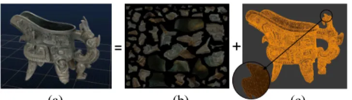
As shown in Fig. 1, a 3D model or object is usually rendered thanks to the combination of geometrical and textural informa-tion. This can be complemented by other types of information depicting for example the light reflection or granularity of the surface. Geometrical information is usually represented as a triangle mesh, defined by a list of triangles positioned in 3D space, and connected by their common edges. Efficient ways of compressing these meshes have been investigated in [1]. The textural information generally consists of a giant image, called texture map or atlas, describing the whole texture information that is mapped onto the 3D shape at the rendering stage. The correspondence between the texture and the triangles is also described in the mesh file. Texture images are usually coded as still images, with for instance JPEG [2] or even HEVC Intra [3]. This is however inefficient for the two following reasons. First, a texture image is usually defined as an atlas of texture patches, with a flat/smooth background (see Fig. 1(b)). Even if optimizations of the patching arrangement have been proposed to lower the background size [4], [5], [6], [7], the projection of the texture content onto a 2D image introduces unavoidable artificial edges, and this leads to a rate overhead, when the encoding is performed with a regular image coder. Second, the atlas encoder inherits its property from conventional coder, i.e., the whole image has to be decoded. Nevertheless, this is not desirable since only a subpart of the 3D model, and therefore part of the atlas, is usually observed at a given time during
This work was partially supported by the Cominlabs excellence laboratory with funding from the French National Research Agency (ANR-10-LABX-07-01) and by the Brittany Region (Grant No. ARED 9582 InterCOR).
the rendering. It would be much more efficient in terms of rate or memory load if only the needed part of the model could be decoded, as pointed in [8]. The question of random accessibility has been tackled for triangle meshes in [9]. In this work, we consider the problem of random accessibility for the texture information associated to such meshes.
A geometry-aware atlas coder has been proposed in [10] to circumvent the first limitation. This coder takes into account the geometry information at several key stages of the com-pression algorithm, i.e. intra prediction, block scanning and transform. This allows to drastically improve the compression performances. However, random access is not considered and the transmission of the whole image is still necessary. In this work, we propose a novel interactive coding scheme that is adapted to the random access of a user, and nevertheless takes into account the correlation between blocks by using some geometrical information. Instead of relying on a predictive coding approach [11], where the correlation exploitation re-quires the blocks processing/compression order to be fixed, we develop a coder based on the incremental entropy code [12] that can exploit these correlations, whatever the block order processing is. As a consequence, the block decoding order can be decided at the decoder side, once the request is known, such that only the visible blocks are transmitted. In other words, the proposed coder brings random access ability with a reasonable storage overhead compared to [10], but it significantly reduces the transmission rate. Even better, the transmission efficiency is as if the encoder already knew which part would be requested by the user, and can thus be considered as optimal.
(a) (b) (c)
Fig. 1. Decomposition of a 3D model (a) into its texture atlas (b) and its triangular mesh (c).
II. ATLAS CODING WITH RANDOM ACCESS
In this section, we formalize the problem of atlas com-pression with random access at the decoder. As in most conventional image coders, the atlas is divided into blocks
3D Model
User’s navigation path
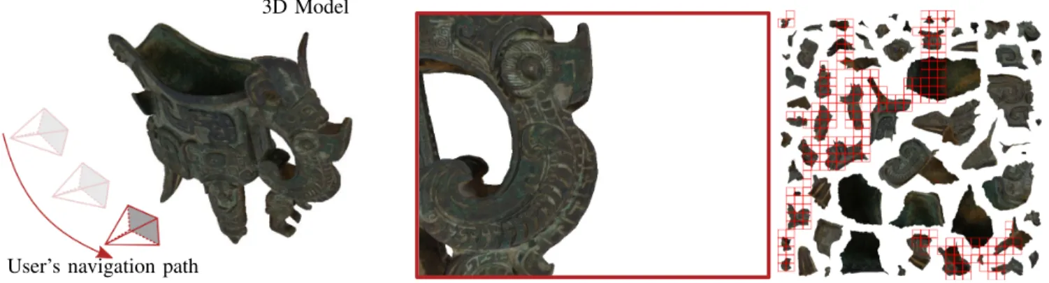
Fig. 2. Example of user’s navigation around the 3D model (left), what he observes at a given instant (center), and the corresponding visible blocks V (in red) in the atlas (right). For better visibility of the blocks, the black background area is turned into white in the atlas.
of dimension B × B that are represented as vectors ai of size
B2× 1 (vectorized in the natural reading order). Let us denote
by N the number of blocks, and let us represent the atlas as a matrix of size B2× N , A = [a
1. . . aN], where the blocks
are organized in the reading order.
The atlas compression with random access is split into two steps. First, the atlas is compressed offline, i.e., it is coded once for all, independently from any user’s observation behavior. This offline encoding operation is denoted by a function f . The entity f (A) is called the stored information, and the storage cost S is measured by S = |f (A)| in which |.| denotes the size of stored data.
When observing a 3D model, only a part of the mesh, and thus of the texture, is visible. This is illustrated in Fig. 2. Let us denote by V the set of block indices that are visible by a user. Given the set V, the second step of the compression is called the online extraction, and is denoted by gV. The entity
gV(f (A)) is called the extracted information and corresponds
to an extractable subset of the stored information that is sufficient to recover the blocks whose index are in V. The extraction cost is measured by EV = |gV(f (A))|. Here, we
emphasize that due to rendering delay constraint, decoding the atlas and reencoding the request can not be performed. The set of extractable information has to be carefully prepared in advance, and this is what makes the interactive compression challenging. For example, when the atlas is encoded with conventional image coders, there is no extractable information but the whole image itself. In other words, with conventional coders one has ∀ V, EV= S. This looks suboptimal, and one
can expect from an efficient interactive coder that EV ≤ S.
This is what we propose in the next section.
Once extracted, the decoder recovers a lossy version of the blocks {˜ai}i∈V. The coding distortion DV is evaluated with
a mean-squared error calculated in the rendered view domain between original view and the view generated with the lossy version of the atlas.
The goal of interactive coding is to minimize each of the elements of the triple (S, EV, DV). Developing such a coder
is particularly challenging for atlases. Indeed, minimizing S implies to jointly compress the ai, and this inevitably
introduces dependencies between them, which makes their partial extraction nearly impossible. In the next section, we explain how we perform the joint compression of the ai such
that only a subset of them can be decoded.
III. PROPOSED INTERACTIVE CODER
In our proposed coder, as in the conventional ones, the blocks ai are coded individually taking into account the
correlation with the neighborhood. Let ai ∼ aj denote the
fact that block aiand aj are adjacent. Two texture blocks are
said to be adjacent if they correspond to two texture pieces that are side by side onto the surface of the 3D model. Let us define the neighborhood of the block with index i as the set of adjacent block indices, N (i) = {j | ai∼ aj}. In [10] as in all
conventional coders, the set of blocks whose index are in N (i) and that are already coded are used to generate a prediction [11], denoted by ˆai. A residue ai− ˆai is then computed and
coded with an arithmetic coder. This efficient compression strategy has however one main drawback: it imposes that the coding order at the encoder is the same as the coding order at the decoder, which contradicts random accessibility.
Instead, we propose to generate a set of several predictions ˆ
ak
i corresponding to different neighbors. More precisely, these
neighbors correspond to different decoding orders that might appear at the decoder side, depending on user’s access. In fact, each ˆak
i corresponds to a prediction generated with blocks
whose indices are in a given subset Nk(i) ⊂ N (i). Each
subset Nk(i) corresponds to a possible decoding order, which
depends on the user’s observation of the 3D model. Thanks to an incremental coder [12], we encode the block ai based on
the different predictions ˆaki such that only the information, needed to complement the ˆaki generated at the decoder, is extracted and sent to the decoder. Here we give more details on the different aforementioned steps. The proposed coder builds upon [10], and adds to it the random accessibility at the decoder side. For the sake of clarity, some useful information from [10] are recalled in the following.
3 4 1 2 1 2 3 4
Fig. 3. The mesh topology enables to retrieve the neighborhood information between triangles 1, 2, 3 and 4, and thus between blue and red blocks, even though they are spread over several patches in the atlas. For blue block i, the two red blocks are in its neighbor set N (i).
A. Neighborhood construction and prediction generation Let us consider a block ai. The neighborhood construction
consists in finding the set N (i) of the adjacent block’s indices. In a classical 2D image, N (i) is simply composed of the 4-connected neighbor indices placed on the previous/next column/row. As discussed in our previous work [10], for some blocks, some textural information that are neighbors in the 3D model can be split into distant blocks in the atlas. Thanks to the mesh topology, we retrieve this proximity and describe it in N (i) in addition to its 4-connected neighbors. This is illustrated in Fig. 3. At the decoder, the user decodes the set of blocks whose index are in V. They are decoded in a given order σ : V → [1, |V|] (see Sec. III-C). For a given request V, the set of blocks available for generating the predictions is NV(i) = {j ∈ N (i) | σ(i) < σ(j)}, i.e., the set of blocks
already decoded. Some reference pixels from the {aj}j∈NV(i)
are put at the border of the block and forward propagated in an optimized directional order.
Considering all the requests V, a set of K scenarios are conceivable at the decoder (with K << |V| since many requests have a common NV(i)). These scenarios lead to K sets Nk(i) and thus K predictions ˆak
i.
B. Graph transform and incremental coding
In order to compact the signal energy on a sparse basis, a transformation is then performed on each block ai and on
each predicted block ˆaki. Blocks of the texture image differ from classical 2D image block because a block may lie on a patch edge, and hence only a subset of pixels is informative. Therefore, it was proposed in [10] to perform a graph-based transform [13] in place of the regular 2D DCT.
One novelty of the proposed coder is to replace the con-ventional arithmetic coder by an incremental coding that can
handle any prediction ˆak
i at the decoder. More precisely, a
codeword is built that can be seen as information (or parity bits) needed to correct the prediction and reconstruct the current block. Interestingly, this codeword is incremental. This means that the codeword can correct the worst prediction, but if the decoder has generated a better prediction, the sufficient bits to decode are extracted from the codeword. In [12] it was shown that theoretically the amount of bits sent to the decoder is the same as predictive coding, i.e. as if the navigation was known by the offline encoder. In practice, we use LDPC codes [14] applied on the quantized and binarized coefficients of the graph-based transform.
C. Geometry-aware decoding order
At the decoder side, only a subset V of the blocks are needed to be transmitted to the decoder. These blocks must be decoded in a smart order σ such that when decoding a block ai, the set of previously decoded neighboring blocks
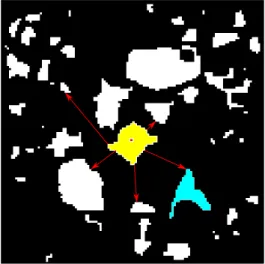
is as large as possible in order to generate the best possible prediction. Finding the optimal scanning order is however an NP-hard problem. We rather propose the approach illustrated in Fig. 4. The first block to be decoded is the access block (in red in Fig 4), which is one block coded in a standalone fashion, meaning that it is encoded independently and thereby can be decoded independently from its neighbors. The assumption, here, is that the navigation always starts at a position where this block is visible. This is without loss of generality because several access blocks can be introduced if several starting points are conceivable. Once this block is decoded, the whole patch where it belongs is decoded (in yellow in Fig 4), by exploring the blocks in a snake fashion so that there is always at least one neighboring block already decoded. Once this patch is entirely decoded, the algorithm explores the other patches where neighboring blocks are present (red arrows in Fig. 4). Then neighboring patches are decoded and so forth, until all requested blocks in V are decoded.
For the later requests of the same user some blocks are already in memory. In that case, instead of starting by the access block, the decoding order begins with any of these blocks in memory and then proceeds as explained above.
IV. EXPERIMENTAL VALIDATION
In this experimental section, we compare our interactive coder with two baselines. The first one, called Whole At-las (WA), encodes the whole atAt-las taking into account the geometry as in [10]. This method is very competitive for compression, and thus minimizes the storage S, but requires, for every user’s request, to transmit the entire atlas. Another baseline is called All Intra (AI), and corresponds to a method that is interactive, but is not able to take into account the correlation between the blocks. In other words, the method AI encodes each block independently as JPEG [2] does. For a fair comparison, the graph-based transform is performed in the method AI (as in ours and WA) by taking into account the geometry.
Fig. 4. Proposed scanning order. The non-black blocks are the ones requested by the client. First, a patch to be decoded is selected (here in yellow). This patch is the first to be decoded because some blocks of this patch either are already available at the decoder (previous request), or can be easily predicted (from a previous request). If this is not the case, an arbitrary patch is selected and the decoding starts at a so called access block (in red) that can be decoded independently of the other blocks. The the whole yellow patch is decoded. Then, the scanning will explore all the patches that are neighbors to the yellow one on the mesh surface, starting for example by the blue one.
(a) (b)
Fig. 5. 3D models used for experiments. (a) Model Ewer. (b) Model Tombs
We used two 3D objects in our experiments, named Tombs [15] and Ewer [16], with atlas image size of 8192x8192 and 4096x4096 respectively. The objects are depicted in Fig. 5. We compress these two models with the three coding schemes leading to three storage costs: Sours, SWA and SAI. We also
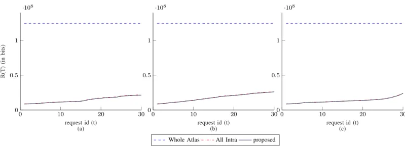
simulate three user navigations around each model, each last for 30 requests corresponding to successive changes of camera orientations and positions. At each instant we record the rate that is needed to satisfy user’s request, leading to three transmission costs rours(t), rWA(t) and rAI(t). In Figs. 6
and 7, we plot the accumulated transmission rates at a PSNR of 38dB for the two models during successive requests, i.e.
R(T ) =
T
X
t=1
r(t).
Similar behaviors were observed for other PSNR values. We can see that our scheme outperforms the schemes AI and WA for two reasons. First, our scheme always has the smallest transmission cost (for the same quality), which demonstrates
the great compactness of the compression. Second, we can see that Rours(t) evolution is smooth with the request which
shows that our scheme transmit what is needed at every instant, and not everything at the beginning of the navigation as the scheme WA does. This is also the case for the scheme AI, but with a higher rate.
The rate results demonstrate the benefits of our approach. This comes however with a small storage size overhead. In order to evaluate its impact, we rely on a comparison methodology proposed in [17], where the Bjontegaard metric is computed on the curve (P SN R, R + λS), for different values of λ. Results are shown in Table I. We can see that when λ = 2, meaning that storage matters more than transmission, the best method is the WA. In other words, both All Intra and the proposed method have a small storage overhead compared to WA, but for smaller λs, i.e., when a trade-off between storage and transmission is desired (transmission cost is becoming important), our method performs better than baselines.
V. CONCLUSION
In this paper, we proposed a new coder for mesh texture that enables interactivity. By replacing classical predictive coding scheme, by an incremental coding, and by adapting the intra-prediction and the block scanning order, we have enabled our coder to transmit only what is requested by a user when looking at the 3D model from some points of view. The experiments demonstrate that, with a reasonable storage overhead, the transmission rate is optimal because only the useful information is sent to the users.
REFERENCES
[1] A. Maglo, G. Lavou, F. Dupont, and C. Hudelot, “3d mesh compression: survey, comparisons and emerging trends,” ACM Comput. Surv., vol. 47, no. 3, pp. 1–39, Feb. 2015.
[2] G. K. Wallace, “The jpeg still picture compression standard,” IEEE transactions on consumer electronics, vol. 38, no. 1, pp. xviii–xxxiv, 1992.
[3] M. A. Saleh, H. Hashim, N. M. Tahir, and E. Hisham, “Review for high efficiency video coding (HEVC),” in 2014 IEEE Conference on Systems, Process and Control (ICSPC 2014), Dec 2014, pp. 141–146. [4] L. Balmelli, G. Taubin, and F. Bernardini, “Space-optimized texture
maps,” in Computer Graphics Forum, vol. 21, no. 3. Wiley Online Library, 2002, pp. 411–420.
[5] M. S. Floater and K. Hormann, “Surface parameterization: a tutorial and survey,” in Advances in Multiresolution for Geometric Modelling, N. A. Dodgson, M. S. Floater, and M. A. Sabin, Eds. Berlin, Heidelberg: Springer Berlin Heidelberg, 2005, pp. 157–186.
[6] L. Velho and J. Sossai Jr, “Projective texture atlas construction for 3d photography,” The Visual Computer, vol. 23, no. 9-11, pp. 621–629, 2007.
[7] Y. Yang and Y. Zhang, “A high-realistic texture mapping algorithm based on image sequences,” in 2018 26th International Conference on Geoinformatics. IEEE, 2018, pp. 1–8.
[8] G. Simon, “Texture images are not regular images:how to leverage geometry information?” IEEE MMTC Review-Letter, vol. 10, no. 2, p. 3, Apr. 2019.
[9] A. Maglo, I. Grimstead, and C. Hudelot, “POMAR: Compression of progressive oriented meshes accessible randomly,” Computers & Graphics, vol. 37, no. 3, pp. 743–752, Feb. 2013. [Online]. Available: http://doi.acm.org/10.1145/2693443
TABLE I
WEIGHTEDBDAVERAGED OVER ALL USERS RELATIVE TO WHOLE ATLAS APPROACH
λ = 2 λ = 0.1 λ = 0.01 λ = 1e−3 λ = 1e−4 All Intra Proposed All Intra Proposed All Intra Proposed All Intra Proposed All Intra Proposed Ewer 5.13 7.28 -2.10 -1.17 -18.18 -19.95 -24.42 -27.25 -25.23 -28.20 Tombs 1.17 3.38 -18.10 -16.51 -60.93 -60.74 -77.56 -77.92 -79.71 -80.15 Average 3.15 5.33 -10.10 -8.84 -39.55 -40.35 -50.99 -52.59 -52.47 -54.17 0 10 20 30 1 2 3 ·10 7 request id (t) (a) R(T) (in bits) 0 10 20 30 1 2 3 ·10 7 request id (t) (b) 0 10 20 30 1 2 3 ·10 7 request id (t) (c)
Whole Atlas All Intra proposed
Fig. 6. transmission rate evolution over the user’s navigation for model Ewer at PSNR 38dB. (a) User 1. (b) User 2. (c) User 3.
0 10 20 30 0 0.5 1 ·108 request id (t) (a) R(T) (in bits) 0 10 20 30 0 0.5 1 ·108 request id (t) (b) 0 10 20 30 0 0.5 1 ·108 request id (t) (c)
Whole Atlas All Intra proposed
Fig. 7. transmission rate evolution over the user’s navigation for model Tmobs at PSNR 38dB. (a) User 1. (b) User 2. (c) User 3. Note that our proposed method is still better than all Intra method, but due to the scale of Y axis it is less visible.
[10] F. Nasiri, N. M. Bidgoli, F. Payan, and T. Maugey, “A geometry-aware framework for compressing 3d mesh textures,” in ICASSP 2019-IEEE International Conference on Acoustics, Speech, and Signal Processing. IEEE, 2019.
[11] T. Nguyen and D. Marpe, “Performance analysis of HEVC-based intra coding for still image compression,” in 2012 Picture Coding Symposium, May 2012, pp. 233–236.
[12] A. Roumy and T. Maugey, “Universal lossless coding with random user access: the cost of interactivity,” Quebec, Canada, Sep. 2015. [13] D. I. Shuman, S. K. Narang, P. Frossard, A. Ortega, and P.
Van-dergheynst, “The emerging field of signal processing on graphs: Ex-tending high-dimensional data analysis to networks and other irregular domains,” IEEE Signal Processing Magazine, vol. 30, no. 3, pp. 83–98,
May 2013.
[14] F. Ye, E. Dupraz, Z. Mheich, and K. Amis, “Optimized rate-adaptive protograph-based ldpc codes for source coding with side information,” IEEE Transactions on Communications, pp. 1–1, 2019.
[15] A. Laurent, “Fethiye tombs, Turquie 3D Model,” 2016. [Online]. Available: https://sketchfab.com/search?q=fethiye-tombs-turquie/ [16] Smithsonian Institution, “Ewer with Birds, Snakes,
and Humans.” [Online]. Available: https://3d.si.edu/explorer/ ewer-with-birds-snakes-and-humans#downloads/
[17] N. Mahmoudian Bidgoli, T. Maugey, and A. Roumy, “Evaluation frame-work for 360-degree visual content compression with user-dependent transmission,” in 2019 IEEE International Conference on Image Pro-cessing (ICIP), Sep. 2019.