A Procedural 3D Modelling and Animation
System Based on Lua
Ben Porter, Jon McCormack
∗, James Wetter and Alan Dorin
Centre for Electronic Media Art
Faculty of Information Technology, Monash University
Caulfield East 3145, Victoria, Australia
May 1, 2012
Abstract
We describe a flexible, script-based system for the procedural gen-eration and animation of 3D geometry. Dynamic triangular meshes are generated through the real-time execution of scripts written in the Lua programming language. Tight integration between programming envi-ronment, runtime engine and graphics visualisation enables a workflow between coding and visual results that encourages experimentation and rapid prototyping. The system has been used successfully to generate a va-riety of complex organic forms and animations including flowers, Haeckel-inspired submarine life, and abstract organic shapes. We use examples in each of these areas to detail the main features of the system, which include a set of flexible 3D mesh operations integrated with a Lua-based L-system interpreter that creates geometry using generalised cylinders.
1
Introduction
Modern games and cinematic effects often require detailed natural forms, such as fauna and flora, to be generated as part of a simulated environment. Mod-elling these complex forms presents an enormous challenge for the CG artist. A successful approach is procedural modelling, where the artist supplies a proce-dure that the computer executes to build and animate a geometric model [4]. Typically the artist specifies form and behaviour at a high-level and the com-puter “fills in the details”, generating the necessary geometric and behavioural complexity automatically.
(Sidebar) Script-based Modelling and Animation The recent prolif-eration of code-based creative systems suggests that programming is now increasingly embraced by artists and designers as a creative medium [1, 2, 4]. These systems, ideal for procedural modelling, have enabled many new and artistically interesting results, e.g. [3]. They are successful because they
(a) (b) (c)
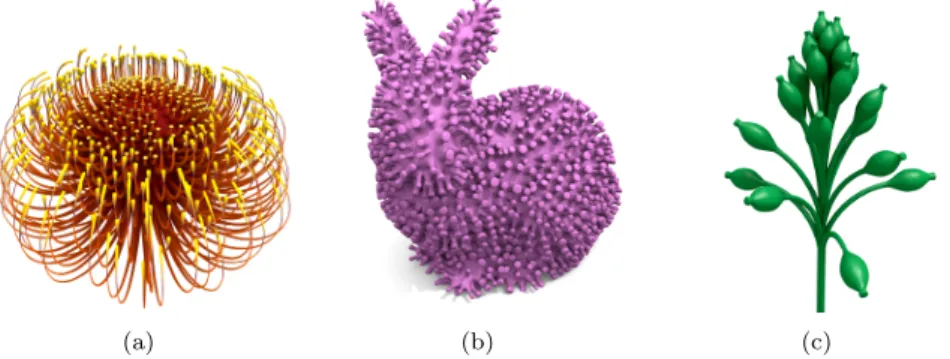
Figure 1: Example models created with the software described in this paper. (a) A Waratah (Telopea) flower created with the extrusion script described in Section 3.1. (b) A stalk-covered rabbit generated by applying the extrusion script to the Stanford Bunny model. (c) A Calcispongiae design modelled with timed L-systems, generalised cylinders, and Lua scripting.
combine the flexibility of programming with a specialised palette of cus-tom functions and support libraries. They hide the underlying complexity of library functionality from the user, presenting a simple, but powerful interface that makes design and experimentation easy.
Professional animation packages support scripting languages too, using either a custom language (e.g. Maya’s MEL, Cinema 4D’s COFFEE ) or a general purpose language, such as Python or Java. General purpose lan-guages have the advantage of a broad user community, extensive use and testing, good documentation, examples, and potentially, user familiarity. Ir-respective of their origins however, when employed in 3D graphics systems these languages must balance programming functionality with the interac-tive modelling and animation components of the software, where scripting is just one feature of many. So while they typically support the creation and manipulation of 3D models, a procedural approach is not necessarily their main focus. For example, the scripting of meshes with changing topologies is not readily supported in a number of systems. This makes the flow of ideas between script and dynamic form less effective than it could be.
References
[1] Zach Lieberman, Theodore Watson, and Arturo Castro. Open Frame-works, 2012. (accessed April 11, 2012).
[2] Casey Reas and Ben Fry. Processing: A Programming Handbook for Visual Designers and Artists. MIT Press, August 2007.
[3] Casey Reas and Chandler McWilliams. Form+Code in Design, Art, and Architecture. Princeton Architectural Press, 2010.
Lua. In Randy Adams, Steve Gibson, and Stefan Mller Arisona, edi-tors, Transdisciplinary Digital Art: Sound, Vision and the New Screen, volume 7 of Communications in Computer and Information Science (CCIS). Springer, Berlin, 2008.
This paper describes Fugu, a new script-driven 3D modelling system devel-oped by the authors. Fugu permits flexible, procedural modelling of dynamic geometric meshes. It supports the generation, manipulation and animation of 3D form using scripts written in the programming language Lua [6], with the specific goal of easily creating the complex organic features found in natural forms. The system is simple: a modelling program is a single Lua module, and the user interface provides the means to program and execute the code, then visualise and interact with the resulting model cohesively.
We will illustrate Fugu’s approach to modelling using examples that high-light different aspects of its functionality and features. Fugu is designed to support multiple levels of model representation and control using the modular-ity provided by Lua. The goal is to provide a tool that allows easy definition and manipulation of a multi-representation model (for example, mesh and armature representations) within a single script.
After describing the operational and interface basics of Fugu in the next section, we will illustrate different aspects of its functionality in Sections 3.1 and 3.2, before discussing the effectiveness of our approach and looking at how the system could be further developed in Section 4.
2
Fugu
The basis of modelling in Fugu is a Lua script that generates and manipu-lates 3D triangular meshes via discrete simulation. Lua is a powerful, efficient, lightweight scripting language, frequently used in computationally demanding real-time applications such as games and multimedia environments [11]. We chose Lua because of its simple syntax, extensible semantics and the ease with which it can be embedded in other software.
Lua scripts interface to a dynamic 3D runtime engine, written in C++, which handles the generation and display of geometry, along with the Fugu user interface (Section 2.1). Fugu scripts are single file Lua modules contain-ing module-scoped variables and two special callback functions, setup() and update() (Section 2.2). An array of functions and libraries (Section 2.3) are exposed to the scripting system to manipulate and control this runtime engine.
2.1
Interface
Fugu’s interactive, code-oriented interface consists primarily of a code pane (Figure 2, left) and a 3D view (Figure 2, right). The design will be familiar to anyone who has used other popular creative-coding systems such as Processing (see Sidebar: Script-based Modelling an Animation). Users can edit a script, press PLAY and see its effect immediately. They can also interact with the generated model while the simulation is running.
The code pane supports standard code editing functionality including syntax highlighting, line numbering, and multi-file editing with tabs. The 3D view uses a trackball-style manipulation of the scene viewport, and viewing modes range from wireframe to ambient occlusion shaded and textured modes. Additionally the user can select smoothly subdivided versions of the geometry (using But-terfly subdivision [3]). A console window at the bottom of the screen presents script syntax and run-time errors.
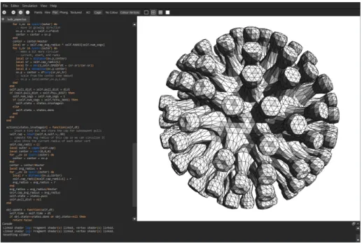
Figure 2: A screenshot of Fugu showing the code pane with syntax colouring (left), 3D interactive view of the model the script generates (right) and the console window for syntax and runtime error reporting (bottom).
2.2
Script Format
A Fugu script is a single file of Lua code written in the form of a Lua module. When a script is loaded, Fugu looks for two special functions in the module: setup() and update().
The setup function is run once at the start of a simulation to specify initial conditions and create any initial meshes. For example, the setup function of Listing 1 creates a new spherical mesh, stores it in a module-scoped variable m, then adds the mesh to the Fugu universe (see Section 2.3).
The update function is called repeatedly and at regular intervals from the time the user presses the PLAY button. Updating continues until the PAUSE button is pressed. The update function receives a parameter specifying the time elapsed since the last update, dt. In Listing 1, the update function iterates over all the vertices in the mesh m and modifies their positions every time step.
Listing 1: An example Fugu script. The setup function creates a spherical mesh. During each update, all the vertices of this mesh are perturbed by a sine function that varies over time and local vertex position.
m o d u l e(... , p a c k a g e . s e e a l l ) l o c a l m f u n c t i o n s e t u p () m = s p h e r e () fgu : add ( m e s h n o d e ( m )) end f u n c t i o n u p d a t e ( dt ) for _ , v in i p a i r s( v e r t e x l i s t ( m )) do v . p = v . p + v e c 3 ( 0 , 0 . 0 1 * sin ( v . p . x + fgu . t ) ,0) end end
2.3
Geometric Modelling Functionality
In addition to the standard Lua library, Fugu provides access to a range of func-tions and datatypes that support 3D mesh modelling. Fugu’s primary object is the 3D triangular mesh, composed of vertices, edges, and triangles. Fugu simplifies working with mesh geometry by facilitating mesh creation and ma-nipulation through an extensive set of functions and datatypes. A summary, classified according to type, is given below.
The universe is a simple scene graph for organising multiple mesh ob-jects and their display. The userdata universe object fgu, contains all the objects of the scene and provides two member functions add(n:node) and make child of(parent:node, child:node) which allow a script to add a node to the universe and to anchor a node’s position to another node respectively. There are two types of nodes: abstract nodes which can be used as invisible an-chors (e.g., as a pivot for an object), and mesh nodes, which transform meshes in the scene. Mesh objects must be wrapped in a meshnode datatype before they are added to the universe (Listing 1).
Affine transformations (stored as homogeneous matrices) transform nodes in the scene graph, or can be applied directly to a mesh to permanently trans-form its geometry. Fugu provides a shorthand for the standard geometric transformation matrices: T(t:vec3) translates a point by the given vector; S(s:vec3) scales by the vector s; R(rad:double, axis:vec3) rotates a point a number of radians around the specified axis; and, Rv(a:vec3,b:vec3) rotates vector a to align with vector b.
A number of mesh creation functions are provided. Standard primitives are created using cube(), sphere(), icosahedron(), etc. The iso(r:int, f:function) function generates an isosurface mesh by sampling the function f using the marching cubes algorithm within a 2x2x2 cube with resolution r. For instance, a sphere could be generated with the following statement:
iso (16 , f u n c t i o n( x , y , z )
r e t u r n d i s t a n c e ( v e c 3 ( x , y , z ) , v e c 3 (0 ,0 ,0)) - 1 end)
be loaded from files (in the popular .obj format), useful for applying functions to pre-built geometry (such as the Stanford Bunny in Figure 1 (b)).
The creation of generalised cylinders—geometric surfaces defined by con-necting a series of cross-section curves distributed along a carrier curve [1]—is also supported. A triangular mesh approximating the surface is constructed from the generalised cylinder, using a novel curve-morphing technique [12].
Cylinders are defined using a Logo-inspired turtle interface, in which a co-ordinate reference frame, the turtle, is created and transformed through space, tracing out cross-sections and carrier curves [8]. The turtle’s member functions change its position and orientation, these include move(d:double), roll(a:double), pitch(a:double) and yaw(a:double). Cross-section and carrier curves are modelled as piecewise cubic B´ezier curves, the control points of which are added by the turtle as it moves through space, using add point(). After defining the cylinder, the member function mesh() creates and returns a triangular mesh version of the cylinder, on which additional mesh-based oper-ations can then be performed. The example in Figure 7 illustrates a complex organic form created in Fugu with generalised cylinders.
(Sidebar) Mesh Implementation: Rather than design yet another mesh representation and manipulation library of our own, we used VCGLib to provide the mesh functionality required in Fugu. VCGLib is a comprehen-sive C++ template library that provides a flexible framework for creat-ing and manipulatcreat-ing triangular meshes (http://vcg.sourceforge.net). Using VCGLib permitted rapid development, allowing us to focus on de-signing new geometric operators and manipulators, leaving VCGLib to take care of mesh representation and geometric integrity. Additionally, VCGLib provides many useful operations, such as Loop subdivision, and has been extensively used and tested in the popular program MeshLab (http: //meshlab.sourceforge.net/). Two alternative libraries, CGAL (http: //www.cgal.org) and OpenMesh (http://www.openmesh.org), provide similar functionality and were considered for our application. CGAL is oriented towards meshes with a fixed topology and is more focused on guar-anteeing correctness of algorithms with its precise kernels, rather than being an efficient real-time format. OpenMesh is a polygonal mesh library based around a half-edge data structure and associated operations. In retrospect OpenMesh may have been a better choice due to its simpler API and more liberal license than VCGLib (LGPL vs GPL).
The lowest-level of mesh manipulation occurs on vertices and faces. Fol-lowing the design inherited from our mesh representation library, VCGLib (see sidebar Mesh Implementation), edges are manipulated implicitly by modi-fying vertices and faces. The vertexlist(m:mesh) function provides access to a mesh’s vertices as a Lua array. A vertex is a user-data object, and has a number of attributes including a position, p, colour, c, and normal, n. List-ing 1 illustrates one way a vertex position can be modified in a script. Should a script retain a reference to a vertex for some time, there is the possibility the reference may become invalid if the vertex is deleted by another part of the script. To protect against such issues, vertices (and faces) are modelled as proxies (see sidebar Proxies). Faces have a similar set of functions, for
exam-ple facelist(m:mesh) returns a list of faces in the mesh, face.n returns the normal of a face, and face:v(i) returns the i’th vertex of the face.
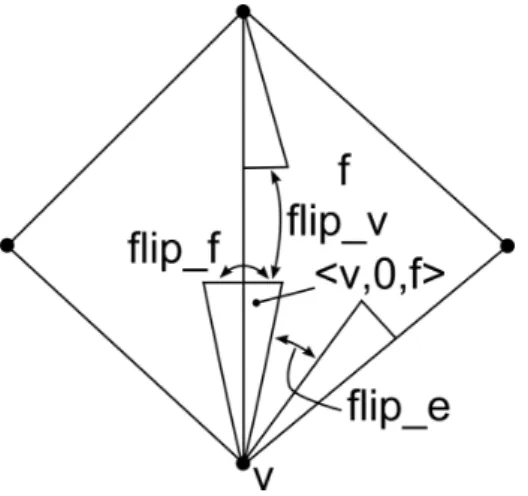
Figure 3: Using a pos to navigate a mesh. This figure shows two faces of a mesh and four pos’es, drawn as triangles connecting the vertex, edge and face referenced by each pos. From the pos <v,0,f> (indicated in the figure), we can move to the vertex above it with flip v, the opposing edge within the face with flip e, or to the adjacent face with flip f. If the mesh is fully connected we can reach any position on the mesh using a sequence of these operations.
When modifying mesh geometry or vertex positions, normals may need to be recalculated to ensure correct shading and display. This is performed auto-matically between update calls or by calling mesh:sync() explicitly.
Fugu provides a simple mechanism for navigating around a mesh: the pos object, which models a cell-tuple [2]. A pos is a <vertex,edge,face> tuple, where vertex and face are the data structures introduced above, and edge is either 0 or 1 (referencing one of two possible edges). A pos uniquely identifies a position on a mesh and provides a set of member functions (flip v(), flip e(), and flip f()) for navigating it over the mesh (see Figure 3). Many of the functions in Fugu return a pos or a list of pos’es. Given a pos, p, the vertex or face it points to can be retrieved as p.v and p.f.
(Sidebar) Proxies: Fugu is designed to allow multiple scripts to run simul-taneously so that, for example, a physics script could simulate the effects of soft-body dynamics on a developing flower, while a sprouting script could be sprouting florets from that flower’s surface. For simplicity we assume that scripts are not running truly concurrently, but rather that they have update() functions that are called sequentially. However, what happens when a script stores a reference to a vertex, and another script deletes that vertex? To safeguard against accessing an invalid object, vertices and faces are stored by proxy. This adds a safe layer of indirection, and offers a valid() function to check if the element targeted for access still exists. VCGLib also shuffles vertices and faces around in memory as elements are deleted, for space efficiency – another reason that necessitates this safety
mechanism. The vertex and face proxies implemented in Fugu also ensure they are updated to point to valid memory locations.
A number of mesh operations for assisting with modelling are provided. Accessor functions return sets of elements: loopv(v:vertex), for example, returns an ordered list of vertices that loop around v, and nearbyv(v:vertex, n:int) returns a list of vertices that are n edges or less away from v. Other functions, such as mesh:smooth subdivide(levels:int) operate on an entire mesh. VCGLib provides a large number of these functions, several of which we expose as Lua functions.
Local operations, such as inset(v:vertex,s:double) (demonstrated in Section 3.1), insets the faces surrounding a vertex and scales them by a given amount, s. extrude(v:vertex, d:vec3, m:double) extrudes the faces sur-rounding a vertex v in direction d, by magnitude m. Given a list of vertices, vl, and a plane defined with position p and normal n, flattenvl(m:mesh, vl:list, p:vec3, n:vec3) flattens all the vertices in the list to lie on that plane.
Mathematics functions include trigonometric functions, linear algebra, Per-lin noise and a variety of interpolative functions. Datatypes for 3D vectors, ho-mogeneous matrices, and quaternions are available as the userdata types vec3, mat4, and quat respectively. Lua’s operator overloading features allow standard mathematical operators (addition, multiplication, etc.) to work on these new types (see Listing 1).
A set of geometric functions are available to assist with performing ge-ometric queries, collision tests, etc. For example, the function distribute points sphere(n:int) returns n equally distributed points on a sphere and perp(v:vec3) returns a normalised vector perpendicular to v.
A number of utility functions for manipulating Lua structures are provided, most of which are adopted from the Underscore.lua library (http://mirven. github.com/underscore.lua/). These functions provide a simplified syntax for iterating over Lua tables and performing functional programming. For exam-ple, the each(t:table, f:function) utility function applies f to each member of t.
Higher-level functions are implemented directly in Lua, while lower-level, CPU intensive functions are implemented in C++. The support library, Lu-abind, was invaluable in allowing easy binding between C++ datatypes and variables and Lua. Our goal is to eventually provide enough functionality so that most mesh operations can be coded purely on the Lua-side, allowing user-created libraries to be easily shared amongst the user community.
Having now described the basics of Fugu operation, along with its principal functions and datatypes, we will illustrate how these features can be used to model 3D form using a series of examples.
3
Example Applications
In this section we describe two applications that highlight the different mod-elling features available within Fugu. The first example demonstrates a mesh
operation for creating continuous animated extrusions. This compound extru-sion operation (implemented as a Lua function that combines several lower-level operations) is used to generate a variety of tubular organic structures over ex-isting meshes. The example also illustrates the general structure of a Fugu script and key mesh-level operations. The second example describes a timed system simulation, based on Calcispongiae development. Unlike previous L-system modelling tools, the geometry generated by the L-L-system’s development can be subject to further modification using Fugu’s mesh operations.
3.1
Extrusion
Extrusion is a fundamental operation in 3D mesh modelling that involves the translation of a group of triangles, typically along their normal, to generate a new form over the region that is swept out. A continuous extrusion can be used to animate the outward growth of a limb, spike, or thorn. This section illustrates how continuous extrusions are modelled and applied over arbitrary meshes in our system. By changing extrusion parameters a variety of different effects can be achieved.
The extrude(v:vertex,dir:vec3,m:double) function extrudes a set of faces adjacent to a specified vertex, along a supplied direction by amount m. To effectively model continuous growth, discontinuities in the surface geometry must be minimised as it undergoes extrusion. One method of achieving this is to use very small extrusion steps. However, in the model described below, we use the function, inset, which performs a zero-distance extrusion, followed by scaling of the end faces.
A continuous extrusion operator can be modelled with a move phase, during which the vertices of the extrusion are translated continuously in a specified direction; and an inset phase, where the faces at the end of the extrusion are inset, forming a new cap to translate. It is useful to consider growth as a single entity, so to model this in Lua we create a Lua object with an internal state and an update function that is responsible for performing the extrusion. This update function returns false when the extrusion is complete, and true otherwise. The internal logic is modelled using a state machine with three states: move, inset, and done. The script for this object is shown in Listing 2.
The inset state executes the inset function (Listing 3) and then returns the machine to the move state. This function doesn’t change self.v (the vertex currently being extruded), which always refers to the vertex at the end of the extrusion. Additionally, the inset function returns the cap: a fan of pos’es (cell-tuples) iterating over the faces located at the active end of the extrusion. This is used in the move state to access the vertices surrounding self.v.
While in the move state, the extrusion shifts self.v by a small amount in the normal direction, then moves the adjacent vertices extracted from self.cap using the function capov(cap:list), which, for a given pos-fan, returns the outer vertices as a Lua array. The vertices are first moved in the extrusion direction, and then scaled from the center so that they shrink. The final step calls flattenvl(m:mesh,vl:list,p:vec3,n:vec3), which flattens the end cap vertices in the list vl, so they sit on the plane defined by position p with normal n. If the vertices have been shifted more than SEG LENGTH, then the state is either changed to inset to generate a new segment, or to done if the required number of segments have been generated. Figure 4 illustrates these stages in
Listing 2: This function creates a Lua object which, by repeatedly calling its update member function, will create an extrusion at the supplied vertex. f u n c t i o n n e w _ s p i k e ( t h e _ m e s h , t h e _ v e r t e x ) - - the p o s s i b l e s t a t e s l o c a l s t a t e s = { m o v e = 1 , i n s e t = 2 , d o n e = 3 } - - c o n s t a n t s for the o p e r a t i o n l o c a l S P E E D = 4 l o c a l S E G _ L E N G T H = .1 l o c a l N U M _ S E G S = 5 l o c a l S H R I N K = .8
- - c r e a t e the o b j e c t and its i n i t i a l i n s t a n c e v a r i a b l e s
l o c a l obj = { m = t h e _m e s h , v = t h e _ v e r t e x , n = t h e _ v e r t e x . n , seg = 1 , d i s t a n c e = 0 , cap = nil, s t a t e = s t a t e s . m o v e } - - d e f i n e the a c t i o n s l o c a l a c t i o n s = {} a c t i o n s [ s t a t e s . m o v e ] = f u n c t i o n( self , dt ) ... end a c t i o n s [ s t a t e s . i n s e t ] = f u n c t i o n( self , dt ) ... end
- - the u p d a t e f u n c t i o n e x e c u t e s the a c t i o n b a s e d on its s t a t e
obj . u p d a t e = f u n c t i o n( self , dt ) if s e l f . s t a t e == s t a t e s . d o n e t h e n r e t u r n f a l s e e l s e a c t i o n s [ s e l f . s t a t e ]( self , dt ) r e t u r n t r u e end end - - r e t u r n the new o b j e c t r e t u r n obj end
Listing 3: The two actions corresponding to the inset and move phases. a c t i o n s [ s t a t e s . i n s e t ] = f u n c t i o n( self , dt ) s e l f . cap = i n s e t ( s e l f . m , s e l f . v , . 9 9 ) s e l f . s t a t e = s t a t e s . m o v e s e l f . d i s t a n c e = 0 end a c t i o n s [ s t a t e s . m o v e ] = f u n c t i o n( self , dt ) l o c a l d i st = S P E E D * dt s e l f . v . p = s e l f . v . p + s e l f . n * d i s t if ( s e l f . cap ) t h e n l o c a l o u t e r = c a p o v ( s e l f . cap ) l o c a l c e n t e r = v e c 3 (0 ,0 ,0) for _ , ov in i p a i r s( o u t e r ) do ov . p = ov . p + s e l f . n * d i s t c e n t e r = c e n t e r + ov . p end c e n t e r = c e n t e r /# o u t e r for _ , ov in i p a i r s( o u t e r ) do ov . p = c e n t e r + ( ov . p - c e n t e r )* S H R I N K end f l a t t e n v l ( s e l f . m , outer , s e l f . v . p , s e l f . n ) end s e l f . d i s t a n c e = s e l f . d i s t a n c e + d i s t if ( s e l f . d i s t a n c e > S E G _ L E N G T H ) t h e n s e l f . seg = s e l f . seg + 1 if ( s e l f . seg <= N U M _ S E G S ) t h e n s e l f . s t a t e = s t a t e s . i n s e t e l s e s e l f . s t a t e = s t a t e s . d o n e end end end
the extrusion process.
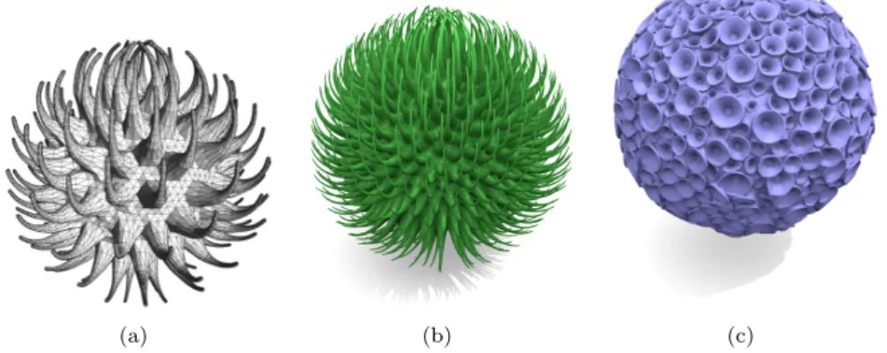
Useful modifications to the continuous extrusion operation include rotating the end cap each segment, making the end cap more circular (to reduce the effect of starting conditions), and creating heterogeneous forms by modifying the extrusion object parameters based on vertex height (see Figure 1 (a) and Figure 3.1 (a,b)). By extruding outwards and then inwards, we can create more interesting shapes, such as suckers (Figure 3.1 (c)). This extrusion operation is general enough to be performed on any smooth manifold mesh. Figure 1 (b) illustrates the operation on the Stanford Bunny, for example.
3.2
Generalised Cylinders
In addition to mesh modification functions, Fugu contains a number of mesh generation methods, the most sophisticated of which is the generalised cylinder. In this section we demonstrate how we can easily model timed, parametric L-systems in Lua and use them to drive Fugu’s generalised cylinder routines,
Figure 4: A sequence generated by applying the new spike operation in Listing 2 to vertex v. The sequence alternates between moving the vertex (and its neighbours) and insetting a new set of faces on the end of the protrusion. The variable outer in Listing 3 refers to the vertices at the end of the cap (as shown).
(a) (b) (c)
Figure 5: (a, b) Forms created by growing tapered extrusions out of a sphere. The spikes curve to orient towards a point above the sphere. (c) The suckers on this object are generated by extruding outwards and then inwards. A collision routine ensures that the suckers only grow until they touch a neighbouring sucker.
Listing 4: Creating a parametric L-system in Lua. a x i o m = ’ B (2) A (4 , pi +1) ’ r u l e s = { ’ A ( x , y ) : y <= 3 - > B ( x ) A ( x *2 , x + y ) ’, ’ B ( x ) : x < 1 - > C ( n o i s e ( x )) ’, ’ B ( x ) : x >= 1 - > B ( x -1) ’ } l s y s = n e w _ l s y s t e m ( axiom , r u l e s )
creating animated growth of organic forms. We then show how this geometry can be manipulated further, by combining the L-system model with the extrusion model introduced in the previous example.
3.2.1 Modelling L-systems with Fugu
L-systems, introduced by Lindenmayer [7], are string rewriting grammars com-monly used to model the development of cellular structures, herbaceous plants and trees [10]. Parametric L-systems represent models as symbolic strings with associated scalar parameters, which develop from an initial symbol string (an axiom) according to a set of rewrite or production rules. To obtain geome-try from an L-system, the produced string must be interpreted by a geomegeome-try building mechanism.
Lua tables are a convenient and efficient data structures for storing an L-system string and specification, but from a user perspective they are too verbose. Therefore, we allow a user to define an L-system using Lua strings (and arrays of strings), which are parsed using Lua’s string matching library (see Listing 4). The function new lsystem creates an L-system object containing the cur-rent string (a table of symbols and a table of associated parameters) and the production rules. For example, the first L-system string contained in the object, lsys, in Listing 4 would be represented as a table with contents:
s y m b o l s = {’ B ’,’ A ’} ,
p a r a m e t e r s = {{’ 2 ’} ,{’ 4 ’,’ pi +1 ’}}
Production rules are also stored using Lua tables. The third rule in Listing 4 would thus be a table containing the following:
p r e d = ’ B ’
p a r a m e t e r s = {’ x ’} c o n d i t i o n = ’x >=1 ’
s u c c = {’ B ’}
s u c c _ p a r = {{’x -1 ’}}
The L-system object has a member function, derive(), which produces a derivation string by iterating through the current string and, for each sym-bol, checking if both the rule predecessor symbol matches and the production conditions are met. If this is the case, the symbol is replaced according to the matched rule.
Parameters and conditions are stored as strings so they can be evaluated dynamically by the Lua interpreter as production rules are matched and applied. This has the benefit of allowing any valid Lua expression (including Lua or Fugu
functions) to be used in a parameter expression or condition; for example, the second rule in Listing 4 illustrates the use of Fugu’s noise function.
At this stage the L-system is purely symbolic, it is then interpreted to gener-ate mesh geometry using the turtle interpretation provided by Fugu’s generalised cylinder functionality (Section 2.3).
3.2.2 Timed Development
Parametric L-systems provide a discrete-time model of development, making continuous temporal development difficult. To overcome this limitation, timed parametric L-systems were introduced [10]. Timed L-system symbols are as-signed an age – a continuous variable representing the time the symbol has been active in the derivation string. This variable also determines when a pro-duction rule should be applied to its associated symbol. A symbol’s age can also be used to drive other animation parameters, such as a primitive’s scale or length [10, Chapter 6].
Our Lua-based implementation of parametric L-systems can be easily ex-tended to include timed symbols. The L-system object stores an additional table with the age of each developing symbol in the produced string. Addition-ally, production rules may include a terminal age, and a minimum age of the predecessor in order for the rule to be applied.
Timed, parametric L-systems can be used to generate animated meshes. A Fugu script first defines an system object in its setup function. The L-system’s member function derive(dt:double) is then called within the script’s update function. The derive function updates each active symbol’s age by dt, and then applies the appropriate production rules as necessary. Once the state of the L-system has been updated, it is re-interpreted to generate a new mesh. Using this method, we designed a timed, parametric L-system in Fugu to produce a form inspired by Calcispongiae [5]. The result is an animated sequence of geometric models with smooth and fluid continuous development. Figure 6 shows a sequence of still images from this development. The appendix contains details of the L-system used.
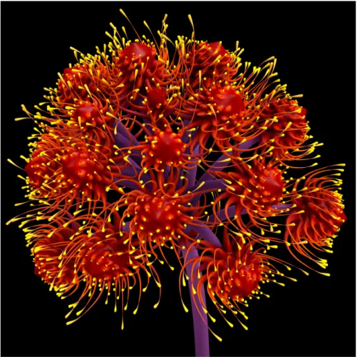
The L-system generates a triangular mesh, which can then have other mesh operations applied to it. Trivially we can just return the plain mesh and operate on it, but more interesting behaviour can be modelled if information is shared between the L-system model and Lua. For the model shown in Figure 7, we used texture coordinates assigned to the generalised cylinders to control the placement and properties of extrusions grown on the mesh.
As these examples show, the procedural flexibility of scripts, combined with powerful mesh manipulation and development functions makes the specification of complex models relatively easy.
4
Conclusions
The benefits of procedural design are well known, but the accessibility of ad-vanced procedural modelling tools to artists has, until recently, been limited. With new code-based creative tools such as Fugu, this goal becomes increas-ingly viable. However, there are many additional features that could extend the capabilities of our system to increase its versatility.
Figure 6: A growth sequence of a timed, parametric L-system built in Fugu.
The most useful enhancement would be multiple, complementary model rep-resentations. For example: a geometric mesh, an armature for skeletal anima-tion, and a physical simulation system. Ideally, these different representations can be flexibly connected together. This could, for example, allow a user to procedurally generate tentacles growing out of a creature using the extrusion functions, while simultaneously growing an armature inside each tentacle in or-der to animate it. The armatures could in turn define geometric primitives used in a physical simulation, preventing tentacles from intersecting and allowing them to move or propel the creature.
Morphogen simulation (based on biological patterning) can generate a va-riety of self-organising natural shapes and patterns, and has been widely used in modelling development [9]. Allowing user-defined attributes for the vertices and faces would facilitate this feature in Fugu, and permit greater flexibility in modelling development. For instance, a user could specify that their model re-quires a new, per-vertex variable morphogen. This could also extend to per-face attributes, for instance to define material properties for rendering. Simulation of morphogen diffusion could be implemented as additional Lua functions, al-lowing users to easily modify developmental behaviour or implement unusual effects within scripts.
There are also some technical challenges that need to be overcome to support the real-time creation of more complex models. The smooth-subdivision visual-isation used in the current system is performed in a single-thread on the CPU, and thus impacts significantly on overall performance when active (viewing more than 2 levels of subdivision is not currently practical for interactive performance on standard desktop computers). GPU-based smooth subdivision using tessella-tion shaders found in recent hardware would dramatically improve visualisatessella-tion performance (see e.g. www.opengl.org/registry/specs/ARB/tessellation_ shader.txt).
The core of Fugu has been designed to be independent of any visual repre-sentation, making it easy to incorporate it into a real-time game engine, and
Figure 7: A flower-like form built with a combination of L-systems, generalised cylinders, and mesh extrusions. This hybrid model combines the models used to generate Figure 6 and Figure 1 (a).
could take advantage of its visualization features (e.g. shadows, post-processing, shaders). Further development would be required to ensure real-time frame rates however.
The novelty of our system derives from its combination of a rich set of geo-metric mesh operations with a fast and flexible scripting language. As similar systems have demonstrated in more general “creative coding” environments, the use of relatively simple function libraries combined with an initialisation and per-frame step programming model makes it easy for artists and designers to rapidly create animated sequences. Fugu brings this ease of use and experimen-tal flexibility to 3D animated mesh modelling. We hope that as its development continues, Fugu will be able to tackle even more complex modelling tasks in the procedural generation of developing organic form.
You can download a copy of Fugu, including source code, from www.csse. monash.edu.au/cema/fugu.
5
Acknowledgements
This research was supported by an Australian Research Council Discovery Projects grant DP1094064.
6
Appendix
The timed, parametric L-system used to generate the Calcispongiae shown in Figure 6 is shown below. A symbol X with parameters p1. . . pn and age α is
denoted by (X(p1, . . . , pn), α). Non-timed symbols are also allowed, in which
case the outer parentheses and age are omitted. The turtle commands for each symbol are specified in the table.
The L-system consists of three main components, modelled with symbols A, B and C. Symbol A generates the first section of the stalk before any branching has occurred, symbol B is responsible for placing the branches in a helical pattern based on the golden angle, and symbol C is responsible for generating each branch and its terminal bulbs.
axiom : ∧(−.5π)G#(1)(Gsc(3), 0)GsG#(0)(f (6), 0)(A(2, 1, 10, 0.02), 0)Ge production rules (A(l, w, n, b), 1) : n > 0 → (S(l, b, w), 0)(A(l, w, n − 1, b), 0) (A(l, w, n, b), 1) : n = 0 → (B(2, 0.7, 25, 0.09), 0) (B(l, w, n, b), 1) : n > 0 → [\(2.39996n)(Gsc(w), 0)Gs(f (l), 0)(C(l, w, 10, b), 0)Ge] . . . (S(1, 1, 1), 0)(B(l, w, n − 1, 0.9b), 0) (C(l, w, n, b), 1) : n > 0 → (S(l, b, w), 0)(C(l, w, n − 1, b), 0) (C(l, w, n, b), 1) : n = 0 → (S(1.5l, 0, 1.1l), 0)(S(1.5l, 0, l), 0) . . . (S(l, 0, 0.3l), 0)(S(.5l, 0, 0.6l), 0) (S(l, b, w), 30) → S(l, b, w) (Gsc(x), 10) → Gsc(x) (f (x), 15) → f (x) symbol interpretations
S(l, b, w): Add a segment to the generalised cylinder of length l pitched by angle b, and ending with scale w
G#(n): Set the cross section
Gsc(x): Set the scale for the next cylinder control point Gs: Begin a generalised cylinder
Ge: End a generalised cylinder \(x): Roll by x radians f (x): Move forward x units ∧(x) : pitch by x radians
References
[1] G.J. Agin. Representation and description of curved objects. Technical report, Stanford Artificial Intelligence Report AIM-173, 1972.
[2] E. Brisson. Representing geometric structures in d dimensions: topology and order. In Proceedings of the fifth annual symposium on Computational geometry, SCG ’89, pages 218–227, New York, NY, USA, 1989. ACM. ISBN 0-89791-318-3.
[3] Nira Dyn, David Leven, and John Gregory. A butterfly subdivision scheme for surface interpolation with tension control. ACM Transactions on Graph-ics, 9(2):160–169, April 1990.
[4] David S. Ebert, F. Kenton Musgrave, Darwin Peachey, Ken Perlin, and Steven Worley. Texturing & Modeling: A Procedural Approach. Morgan Kaufmann, San Francisco, CA, third edition, 2003.
[5] Ernst Haeckel. Kunstformen der Natur. 1904.
[6] Roberto Ierusalimschy. Programming in Lua. Lua.org, 2 edition, March 2006.
[7] Aristid Lindenmayer. Mathematical models for cellular interactions in de-velopment, parts I and II. Journal of Theoretical Biology, 18:280–315, 1968. [8] Jon McCormack. Generative modelling with timed L-systems. Design
[9] Benjamin Porter and Jon McCormack. Developmental modelling with SDS. Computers & Graphics, 34(4):294 – 303, 2010. ISSN 0097-8493.
[10] Przemyslaw Prusinkiewicz and Aristid Lindenmayer. The Algorithmic Beauty of Plants. Springer-Verlag, 2nd edition, 1996.
[11] W. Smith and G. Wakefield. Real-time multimedia composition using Lua. In Randy Adams, Steve Gibson, and Stefan Mller Arisona, editors, Trans-disciplinary Digital Art: Sound, Vision and the New Screen, volume 7 of Communications in Computer and Information Science (CCIS). Springer, Berlin, 2008.
[12] James Wetter. Generalised cylinders with application in developmental modelling. (Honours Thesis, Clayton School of Informsation Technology, Monash University), November 2011.