HAL Id: lirmm-01421006
https://hal-lirmm.ccsd.cnrs.fr/lirmm-01421006
Submitted on 21 Dec 2016
HAL is a multi-disciplinary open access
archive for the deposit and dissemination of
sci-entific research documents, whether they are
pub-lished or not. The documents may come from
teaching and research institutions in France or
abroad, or from public or private research centers.
L’archive ouverte pluridisciplinaire HAL, est
destinée au dépôt et à la diffusion de documents
scientifiques de niveau recherche, publiés ou non,
émanant des établissements d’enseignement et de
recherche français ou étrangers, des laboratoires
publics ou privés.
Methodology for Power Mode selection in FD-SOI
circuits with DVFS and Dynamic Body Biasing
Yeter Akgul, Diego Puschini, Suzanne Lesecq, Edith Beigné, Pascal Benoit,
Lionel Torres
To cite this version:
Yeter Akgul, Diego Puschini, Suzanne Lesecq, Edith Beigné, Pascal Benoit, et al.. Methodology for
Power Mode selection in FD-SOI circuits with DVFS and Dynamic Body Biasing. PATMOS: Power
and Timing Modeling, Optimization and Simulation, Sep 2013, Karlsruhe, Germany. pp.199-206,
�10.1109/PATMOS.2013.6662174�. �lirmm-01421006�
Methodology for Power Mode Selection in FD-SOI circuits with
DVFS and Dynamic Body Biasing
Y. Akgul
1, D. Puschini
1, S. Lesecq
1, E. Beigne
1, P. Benoit
2, L. Torres
2Abstract—Embedded systems need ever increasing computa-tional performances. Since they have limited energy resources, power consumption has to be minimized. Dynamic Voltage and Frequency Scaling (DVFS) techniques combined with Body Biasing techniques decrease the power consumption of a chip by providing just enough computational performance to the chip so as to finish the task at its deadline. A Power Mode (PM) is defined with the clock frequency F applied to the chip and the power P consumed by the chip. Executing tasks with the 2 neighbor frequencies of the target frequency should minimize the power consumption. Unfortunately, this choice is not always optimal since the set of available PMs may not fulfil the convexity property anymore when 3 actuators are considered. Here, a method is proposed to tackle this issue. PMs are selected to form a discretely convex subset. Results for a ring oscillator in FD-SOI exemplify that the proposed approach can save power consumption.
I. INTRODUCTION
The ever increasing requirements in computational perfor-mance for embedded systems have lead to an increase in the clock frequency applied to the circuit. Meanwhile, the computational performance requirements and power efficiency have become highly critical for mobile platforms powered by batteries. As a consequence, the designer has to implement methodologies to meet the computational performance require-ments while minimizing the power consumptionP . Note that this latter actually depends on the supply voltageVdd applied to the circuit, the clock frequencyF , the threshold voltage VT, the operating temperatureT◦, the circuit activityA, etc. The circuit activityA corresponds to the average number of cells which switch during a clock cycle. Moreover, P is usually split in “leakage” and “dynamic” parts.
Several solutions can be implemented to reduce the power consumption. First, large chips can be split in several Frequency Islands, leading to the well known Globally-Asynchronous-Locally-Synchronous (GALS) archi-tectures [1]. Furthermore, the voltage of each island can be modified. So, each island can be switched on/off depending on the amount of tasks it has to run. This solution when applied at fine-grain is admitted saving power consumption. Moreover, when associated with Dynamic Voltage and Frequency Scaling (DVFS), the gain can be tremendous. In this situation,Vddand F applied to each island should ideally be adapted to provide enough computational performance to execute the task running
1CEA, LETI-MINATEC Campus, 17 rue des Martyrs, 38000, Grenoble,
2Laboratoire d’Informatique, de Robotique et de Micro´electronique
de Montpellier (LIRMM), Universit´e Montpellier 2, UMR 5506−CC477, 161 rue Ada 34095 Montpellier, Cedex 5, France
pascal.benoit,[email protected]
on the Processing Element (PE) burried in the island, but no more.
DynamicVT Scaling (DVTS) techniques can also decrease the power consumption by adjusting the threshold voltageVT to balance the leakage power and minimize the overall power consumption. The threshold voltage VT is modified thanks to the body bias voltageVbbeither to reduce the power consump-tion while maintaining/increasing computaconsump-tional performance, or to increase the computational performance for the same power budget/a lower one.
Power Management has become even more difficult for advanced technologies that operate with Vdd close to VT, leading to “Near-Threshold Circuits” (NTCs) [2]. Actually, decreasing Vdd is still considered the most efficient way to reduce dynamic power consumption. However, running atVdd very close to VT induces new side effects, e.g. the leakage power has a great influence on the overall power budget. At the same time, the clock frequency F applied to the PE must be carefully chosen to avoid timing faults. Thus, the triplet(Vdd, F, Vbb) cannot be independently chosen to ensure a functional operating point that satisfies the computational performance constraints. Moreover, even if one triplet makes the chip functional, it might not be the most power efficient op-erating point [3]. As a consequence, choosing of an opop-erating point is an intricate problem, even worse when 3 “actuators” (i.e. supply voltage, clock frequency and body bias voltage) are considered.
In the present work, the performance constraint which is considered is the speed as the task T running on the PE has to meet its deadline d. A methodology for selecting the operating points to be applied to the PE for taskT is proposed. TaskT has to meet its deadline d while minimizing the power consumption. The notion of “operating point” is preferred to the classical (Vdd, F ) or (Vdd, F, Vbb) set of actuator values. Indeed, it is more general and it does not care about a particular implementation. The power consumption depends on the operating point values, leading to the so-called “Power Modes” (PMs) [4]. As the speed (related to the clock frequency F ) cannot be chosen independently from Vdd and/or Vbb, the plane (F, P ) is considered here. Note that P (F ) can be a continuous function, a piecewise continuous function, or even P can take its values in a finite set of values. Therefore, this choice encompasses a wide variety of situations a designer might encounter regarding the implementation of the actuators that feed the PE (e.g. hopping technique [5] [6], DC-DC converter for Vdd [7], Frequency Locked-Loop or frequency division [8], etc.).
of a finite set S of PMs obtained by 3 actuators. First, a discretely convex subset S of PMs is extracted from the initial set S. This step does not require to distinguish leakage and dynamic power; it is solely based on total power consumption figures which can be estimated at design time or measured on the chip. Then, an optimal selection of PMs applied to the PE for a given task to meet its deadline while minimizing the power consumption is proposed. This step is close to part of the results proposed in [3].
The paper is organized as follows. Section II provides an overview of previous works dedicated to the choice of operating points so that task T meets its deadline d while minimizing the PE power consumption. Section III summa-rizes the results proposed in [4]. They show how and where an intermediate PM could be added when2 PMs are already available on the PE (low power and high performance modes). The intermediate PM can be fixed in order to minimize the power consumption for a given range of workload. Then section IV is dedicated to the choice of PMs applied to the PE when a finite set is available. Results show that not all PMs are optimal. The method is exemplified in section V. Power figures have been obtained with the simulation of a ring oscillator in STMicroelectronics 28nm FD-SOI technology and it can be extended to a more complex circuit. Furthermore, the concept has been evaluated in a FD-SOI context and it can be reused for other CMOS technologies. Finally, section VI sums up the main contributions and provides future work directions.
II. RELATED WORKS
Several power management techniques can be found in the literature. They can broadly be classified in two main families, namely, the “static” techniques that are applied at the circuit design phase or test phase, and the “dynamic” ones that adapt at run-time the operating point in order to decrease the power consumption. In this latter family, the operating point is modified by acting on up to3 actuators (Vdd, F, Vbb). A subset of these works is now shortly discussed.
The power consumption of a PE for a given computational performance can be optimized during the test phase by an ap-propriate setting ofVbbandVdd[9]. However, the optimization is done once and it cannot take into account dynamic varia-tions. When Dynamic Frequency Scaling (DFS) is associated, the power consumption can be decreased but it is well known that DFS cannot reach the minimum power consumption when tasks with different computational performance demands are executed on the PE.
Another way to reduce the power consumption is to use Dynamic Voltage and Frequency Scaling (DVFS) techniques. The main idea is to adapt at run-timeVdd andF to reduce the power consumption while maintaining the computational per-formance (e.g. meet the time constraint for the task processed on the PE). This situation obviously requires information about the task (amount of work) to choose the accurate clock frequency. Several implementation variants of this technique exist, depending on the choice of the Vdd and F actuators, leading to discrete sets or continuous intervals of values that
can be applied to the PE. [10] determines the “optimal” (Vdd, F ) couple applied to a PE to execute a task when a Dynamic Voltage Scaling (DVS) technique (with a continuum of values in a given interval) is used in conjunction with a finite set of frequencies. A ratio energy/deadline is taken into account to determine if the operating point is efficient or not. The frequency profile (i.e. the number of frequencies applied and their individual time duration) depends on the deadline of the task.
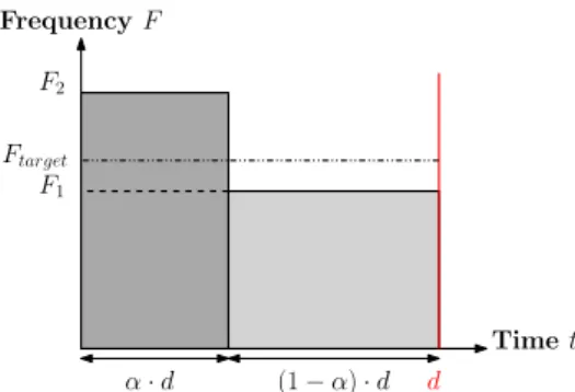
Other works consider that a finite setS of operating points (Vdd, F ) is available. For instance, a Vdd-hopping [5] is implemented for theVdd actuator, leading to few (usually2 or 3) available supply voltages, while a finite set of frequencies can be applied with a Dynamic Frequency Locked-Loop [8]. In these situations, the computational performance demand is satisfied thanks to the application of several PMs, each PM being defined by a couple (Vdd, F ). Note that a unique operating point is applied if the frequency fulfiling the con-straint (hereafter called target frequency Ftarget) exists in the frequency set. When Ftarget is not in the frequency set, the computational performance is usually met by the application of 2 PMs in “hopping” execution. Such an execution consists in processing part of the task T with frequency F2≥ Ftarget during the time period α· d and the remaining part of T is processed with frequency F1 < Ftarget until the deadline is met such that:
Ftarget= α· F2+ (1− α) · F1 F2 Frequency F F1 Time t d α· d (1− α) · d Ftarget
Fig. 1: Execution of task T with deadline d in “hopping” execution.
Figure 1 illustrates this “hopping” execution. [11] ap-plies this concept with (Vdd,1, F1) and (Vdd,2, F2) such that F1 ≤ Ftarget ≤ F2, F1 = max{Fi, Fi≤ Ftarget}, F2 = min{Fi, Fi ≥ Ftarget}. However, this choice is not always optimal, depending on someP (F ) properties. Actually, it can be proved [3] that the optimal power consumption is reached when the neighborsF1andF2are used if the points ofP (F ) form a discretely convex set as defined in [12]. This property is not always fulfiled when DVFS techniques are combined with the body bias voltage actuator. Actually, with new technologies such as FD-SOI, the body bias voltage Vbb actuator has a greater influence because the modification range ofVbbis very wide.
[13] proposes to use a body bias voltage Vbb actuator to reduce the leakage power consumption while [14] [15] show that the use of the Vbb actuator in conjunction with a DVFS technique is more efficient to reduce the power con-sumption while maintaining or increasing the computational performance. Other works propose to reduce the device power consumption by reaching a constant ratio of the leakage power consumption to the dynamic power consumption [16] or a constant ratio of the switching current Isw to the leakage current Ileak [14]. However, the power consumption is not necessarily minimized by keepingIsw/Ileak constant [9].
Dynamic Voltage and Frequency Scaling (DVFS) together with Body Biasing techniques are combined in order to reach a trade-off between reliability, computational performance and power consumption [17]. This latter work considers that Vdd andVbb are continuous on known intervals. The optimization problem is expressed as a Geometric Program one [18].
[3] proves that an optimal speed profile is reached when certain conditions are fulfiled. To obtain this result, the Q-function is introduced which corresponds to the ratio of power to speed. The optimal speed profile is attained when the relation Q-function/speed is convex. Furthermore, the authors state that devices by default satisfy this convexity property. This assertion is correct if the PE is managed by 2 actuators (e.g.Vdd andF or VbbandF or Vdd andVbb). Nevertheless, for advanced technologies, when3 actuators are combined, this statement depends on the range of each actuator. Therefore, a selection of PMs has to be implemented. In the present work, 3 actuators are supposed to feed the PE so that a finite discrete setS of PMs can be applied. Moreover, no discrete convexity conditions as defined in [12] are assumed for S because the subset is unlikely to fulfil this condition.
III. INFLUENCE OF THE DISTRIBUTION OFPOWERMODES ON POWER CONSUMPTION
The main objective of the paper is to provide a methodology to optimally select from a PM set the PMs to be applied to an island. However, the power reduction greatly depends on the PM distribution. A method to optimally fix a3rd PM between 2 PMs for a given range of workload is now summarized.
Each island can be composed of a PE, cache or scratch-pad memory. It is supposed to possess its own frequency and/or supply voltage actuators. Figure 2 depicts a simplified overview of an island. A task T to be run requires Nc clock cycles for completion, taking into account memory and peripheral accesses. T runs on the PE and must meet its deadline d. To fulfil these requirements, the PE should theoretically run at Ftarget ≥ Nc
d . Since a discrete frequency actuator is taken into consideration, ifFtarget is not available, higher and lower frequencies are applied successively to reach the required computational performance on average, with “hopping” execution [5].
A Power Mode (PM) is defined as a pair(F, P ), where F is the clock frequency, and P the power consumed. P depends on F and on a set of parameters (activity A, supply voltage Vdd, body bias voltageVbb, temperatureT◦, etc.) [4]. A given
Frequency actuator Voltage actuator PE Lo cal con trol Fref Vdd,ref Island d, Nc
Fig. 2: Schematic of an island with 2 actuators. d is the deadline and Nc is the number of clock cycles.
Frequency Power Fn Fn−1 F1 Pn Pn−1 P1 P Mn P Mn−1 P M1
Fig. 3:n PMs (Fi; Pi),i = 1 : n.
P F P M1 P M2 P M3 P M4 F1 F2 F3 F4 P1 P2 P3 P4
Fig. 4: P as a function of F with n PMs (Fi; Pi),i = 1 : n, n = 4.
PE is assumed to operate in n PMs, depicted in Figure 3 and in Figure 4, depending on different combinations of internal with external parameters. Recall that the concept or PM has been introduced because it is independent of the particular implementation of the actuators (e.g. Vdd-hopping [5],
Vbb-hopping [6], DC-DC converter [7]).
An analytical study is presented in [4] when 3 PMs are available on the PE. In this latter paper, it has been proved that for a given distribution of the PMs, a maximum gain in power consumption can be attained for a specific workload W L range, when the3rdPM (PM2) is properly fixed between PM1 and PM3 see Figure 5. The workload is defined as the load of the processor. It corresponds to a ratio of target frequency Ftarget to the maximal frequency Fmax available on the PE, W L = Ftarget
Fmax .
(a) Consumption improvement when a 3rdPM is added [4].
(b) Maximum consumption improvement when a 3rdPM is added [4].
Fig. 5: Improvement of the power consumption when a 3rd PM is added vs. normalized workload [4].
Note that the results in [4] might be used in the current work in order to optimally fix the set of PMs for a given range of activity.
IV. POWERMODE SELECTION IN A DISCRETELY NON-CONVEX SET
In the present work, the operating points are obtained thanks to 3 actuators to adjust the supply voltage Vdd, the body bias voltageVbb and the clock frequencyF of an island (see Figure 6). In Multiprocessor System-on-Chips, sensors and actuators are distributed in each island. In order to reduce their Silicon overhead, discrete mechanisms are preferred to continuous ones. Here, Vdd is considered as a finite set of values, supplied for example by a hopping mechanism. The clock frequencyF is discrete with a few achievable values. For instance, it could be provided by a Digital Frequency Locked-Loop [8]. The body bias voltageVbbactuator takes its values in a small finite discrete set. It could be furnished through a Vbb-hopping technique [6]. Therefore, there is a finite set of PMs S = {(Pi, Fi), i = 1 : n}, where Fi ≤ Fi+1 for all i = 1 : n− 1. This set is not necessarily discretely convex as defined in [12]. In this section, a methodology to select the PMs distribution will be presented. This methodology extends
the results of [3] while the method proposed in [4] can be applied to choose the distribution of PMs in S.
Frequency actuator Voltage actuator PE Lo cal con trol Fref Vdd,ref Island d, Nc
Body bias actuator
Vbb,ref
Fig. 6: Schematic of an island with 3 actuators. d is the deadline and Nc is the number of clock cycles.
Definition. A set is defined to be convex on an interval I if and only if (see Figure 7)∀F1, F2∈ I, ∀β ∈ [0, 1],
P (β· F1+ (1− β) · F2)≤ β · P (F1) + (1− β) · P (F2) (1) withP (F ) the power consumption related to F.
In other words, a set is defined as convex if every point of the curve P (F ) between two points is situated below the segment of line connecting these points.
P (F2) β· P (F1) + (1− β) · P (F2) P (β· F1+ (1− β) · F2) P (F1) F1 F2
P
F
β· F1+ (1− β) · F2Fig. 7: Example of an increasing convex setP (F ). In section A of the Appendix, it is proved that the use of (F1, F2) in “hopping” execution with F2 just above the target frequency Ftarget and F1 < Ftarget, minimizes the power consumption when S is discretely convex. Moreover, section B of the Appendix shows that the use of (F1, F2) in “hopping” execution with F1 ∈ S just below Ftarget and F2 > Ftarget, minimizes the power consumption when S is discretely convex. Finally, in section C of the Appendix, deduced from section A and section B of the Appendix, it is shown that the use of the 2 neighbor frequencies of Ftarget will minimize the power consumption in “hopping” execution when the set of points is discretely convex. Note that this result
is similar to the one in [3] where the authors prove that the optimum speed is reached for an execution of the task with a combination of the two neighbor frequencies which belong to the convex set of the Q-function in function of the speed. Here, the proof is conducted directly on P , not on the Q-function. Thus, to ensure an optimal “hopping” execution, a discretely convex subset of PMs S must be extracted from S.
Therefore, the proposed method is composed of two parts. The first one consists in finding the discretely convex subset S of S since new technologies do not necessarily lead to a convex setS. The second part of the methodology consists in executing tasks with the two frequencies surroundingFtarget in S [3]. The main objective is to apply the target frequency. However this frequency can be reached only by applying a PM or a combination of PMs. The aim of the proposed method is to reduce the total power consumption whatever the ratio of the leakage power consumption to the dynamic power consumption.
To summarize, since the set S is not always convex as supposed in [3], a subset of PMs has to be defined in order to fulfil the discrete convexity hypothesis. Then the “hopping” execution approach can be applied. Note that the present work directly deals with power consumption figures, without any power consumption equation.
V. APPLICATION IN THE CONTEXT OFFD-SOI
TECHNOLOGY
In section IV, it has been proposed to select the PMs that belong to the discretely convex subset S of S, and to process tasks only with the points belonging to S. This proposition enables to save more power when compared to an execution of the tasks without an initial selection of the PMs. After the selection phase the PMs in the discretely convex subset S are used. In fact, the main purpose of this proposition is to minimize the power consumption while satisfying the time constraint. However, to apply the proposed methodology, the PMs have to be characterized, i.e. the power consumption has to be quantified. For instance, the power consumption can be determined thanks to voltage and temperature sensors [19] combined with activity sensors [20] or with current sensors [21] or obtained by simulation.
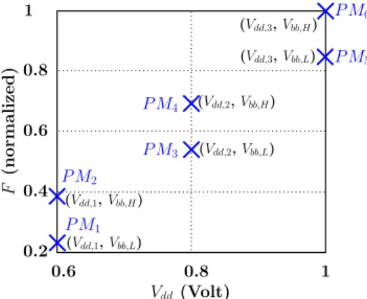
The testbench is a ring oscillator in STMicroelectronics 28nm FD-SOI technology. In this example, 2 levels of body bias Vbb and3 levels of supply voltage Vdd are available on the PE. Note that in [22], the number of supply voltages available is 3 and there is more than a dozen levels for the body bias voltage. The voltage values are: Vdd,1 = 0.6 Volt (V), Vdd,2 = 0.8 V, Vdd,3 = 1.0 V, Vbb L = 0 V (unboosted level) and Vbb H = 1.2 V (boosted level). A ring oscillator has been simulated. Its oscillating frequency depends on the supply voltage and the body bias voltage. It has also a constant activity, here equal to100%.
Figure 8 represents the frequency F in function of Vdd with Vbb L the unboosted level and Vbb H the boosted one. Nevertheless, the representation in the(F, P ) plane in Figure 9 is preferred to properly select the PMs that are in the discretely
TABLE I: Values for each PM of the supply voltage Vdd, the body bias voltage Vbb, the normalized frequency F , the normalized power consumption P .
P M Vdd(V) Vbb(V) F (nomalized) P (normalized) P M1 0.6 0 0.2308 0.0484 P M2 0.6 1.2 0.3846 0.1612 P M3 0.8 0 0.5385 0.1852 P M4 0.8 1.2 0.6923 0.4397 P M5 1.0 0 0.8462 0.4651 P M6 1.0 1.2 1.0000 1.0000
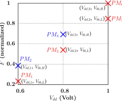
convex set. Figure 9 shows the curve of power consumption P in function of the available frequencies F for the 3 supply voltageVdd (Vdd,1,Vdd,2,Vdd,3) and2 values of the body bias voltage Vbb (Vbb L, Vbb H). The normalized PMs values are given in Table I (see Figure 8 as well). As can be seen in Figure 9, the set of pointsS does not form a globally discrete convex set. Thus a subset of points in S are selected to form a discretely convex subset S. This PM subset will be used so as to minimize the power consumption.
The PMs selected from ones in Table I are depicted in red on Figure 9 (P M1,P M3,P M5,P M6). These PMs belong to the discretely convex subset S of S. Therefore, they allow to minimize the power consumption. Hence, in order to perform a task while satisfying its power and time constraints, only the points in the discretely convex subset S (PMs in red in Figure 9) will be applied to the circuit possibly in “hopping” execution way. Figure 10 shows the operating points after the PMs selection step has been performed.
0.6 1 0.8 0.4 0.2 0.8 1 0.6 F (normalized) Vdd(Volt) (Vdd,1, Vbb,L) (Vdd,1, Vbb,H) (Vdd,2, Vbb,L) (Vdd,2, Vbb,H) (Vdd,3, Vbb,L) (Vdd,3, Vbb,H) P M2 P M1 P M3 P M4 P M5 P M6
Fig. 8: Set of available frequenciesF in function of the supply voltageVdd: F (Vdd).
Different situations may appear when executing a task: • If the target frequency Ftarget is available on the PE
and if the PM corresponding to Ftarget belongs to the discretely convex subset S, the PM is applied directly in order to execute the task;
• If the target frequencyFtarget is available on the PE and if the PM corresponding toFtargetdoes not belong to the discretely convex subset S, the 2 PMs in the discretely convex subset S surrounding Ftarget are applied in order
0.6 1 0.8 0.4 0.2 0 0.2 0.4 0.6 0.8 1 P (normalized) F (normalized) P M1 P M2 P M3 P M4 P M5 P M6
Fig. 9: Set of PMs in the(F, P ) plane. Red crosses correspond to PMs in the discretely convex subset.
0.6 1 0.8 0.4 0.2 0.8 1 0.6 F (normalized) Vdd(Volt) (Vdd,1, Vbb,L) (Vdd,1, Vbb,H) (Vdd,2, Vbb,L) (Vdd,2, Vbb,H) (Vdd,3, Vbb,L) (Vdd,3, Vbb,H) P M2 P M1 P M3 P M4 P M5 P M6
Fig. 10: Set of PMs in the (Vdd, F ) plane. Red crosses correspond to PMs in the discretely convex subset.
to execute the task;
• If the target frequencyFtargetis not available on the PE, the 2 PMs that surround Ftarget and which are in the discretely convex subset S are applied.
Now, the power consumed by executing a task with a target frequency Ftarget which is available on the PE but corresponding to a PM that does not belongs to the discretely convex set is compared to the power consume when executing the task with2 PMs in the discretely convex set so as to attain Ftarget on average. For instance, consider the target frequency Ftarget associated toP M4. Executing the task withP M3and P M5 (see Table II) provides to gain 26.04% in the power consumption. Now, if the target frequencyFtargetcorresponds toP M2, the task will be processed withP M1 andP M3(see Table III). In this case, the gain in power consumption amounts to 27.55%. Note that the gain in power consumption is not absolute: the 2 examples given here only the capability of the methodology proposed. A similar study might be done with different activities. Indeed, the total power consumption depends on the average activity. However, the PMs position has to be reevaluated. Then the selection of PMs has to be re-executed as it has been shown in [4] that the gain in power consumption depends on the PMs distribution.
To summarize, the selection of PMs is a necessary phase
TABLE II: PMs selected to execute the task with Ftarget corresponding to P M4.
P M P M1 P M2 P M3 P M4 P M5 P M6
Execution X X
TABLE III: PMs selected to execute the task with Ftarget corresponding to P M2.
P M P M1 P M2 P M3 P M4 P M5 P M6
Execution X X
since it ensures a gain in power consumption if the setS is not globally discretely convex. However, the gain in consumption depends on the workload and on the PMs distribution [4].
VI. CONCLUSION AND FUTURE WORKS
In this paper, the power management problem for a PE when n PMs are available is studied. Most of the works in the literature execute a given task with the 2 neighbor frequencies of Ftarget. However, this choice is not always optimal from a power consumption point of view because the set of available PMs is not ensured to fulfil the convexity property anymore. Actually, to be energy efficient the task has to be performed with PMs belonging to a convex set. The method proposed here overtakes this problem by selecting the PMs that form a discretely convex subset. Furthermore, the proof is given in Appendix. This methodology is exemplified in the case of a discrete set of PMs available on the PE, considering3 actuators. The proposition takes into account the behavior induced by new technologies as tuning parameters have effects on the convexity of the power/speed curve (e.g. Vbb). Numerical results are given to illustrate the proposed power management methodology. They are obtained from the simulation of a ring oscillator in STMicroelectronics 28nm FD-SOI technology. These results attest that executing tasks with PMs in the discretely convex subset permits to save up to27.55% of power consumption.
In future works, the presented method will take into account the switching power consumption overhead. Actually, the switching power consumption could reduce the gain obtained by applying the methodology.
ACKNOWLEDGEMENT
This work has received partial funding from the ARTEMIS Joint Undertaking under grant agreement number 100205 (POLLUX project) and grant agreement number 332987 (AR-ROWHEAD project).
APPENDIX
Proof
F is the set of frequency Fn ∈ R applicable to the circuit and P is the set of power Pn ∈ R such that P : Fn → Pn,∀n ∈ N∗.P (F ) is supposed to be an increasing set. Let Fn−1, Fn, Fn+1 ∈ F, such that Fn−1 < Fn < Fn+1. As
P is increasing on F, Pn−1 ≤ Pn ≤ Pn+1. The notation Pn(i,j) (see Figures 11 and 12) is used to the value of the power corresponding to the frequencyFnlocated on the line’s segment which connects Pi and Pj withi < j, ∀i, j ∈ N∗. The notation aji (see Figures 11 and 12) corresponds to the slope of the segment of line which connectsPi andPj.
Let’s take an example to understand, the value of the power corresponding to the frequencyF4 located on the segment of line which links P3 and P6 will be noted P4(3,6). The value corresponding to slope of the line’s segment connecting P3 andP6 is noted a6
3.
A. Frequency aboveFtarget
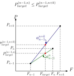
Let Ftarget ∈ F the frequency to reach thanks to the/ “hopping” technique with Fn−1< Ftarget < Fn such in the Figure 11. The aim is to prove that an operating in “hopping” execution betweenFn−1andFn will not consume more than an operating in “hopping” execution betweenFn−1andFn+k, ∀k ∈ N∗, i.e. the goal is to demonstrate that:
Ptarget(n−1,n)≤ P (n−1,n+k) target Pn+k Ptarget(n−1,n+k) Pn Ptarget(n−1,n) Pn−1 Fn−1 FtargetFnFn+k
P
F
a
n+k n−1a
n n−1Fig. 11: Example of 3 possibles frequencies in the plane (F, P ).
The value corresponding toFtarget on the segment which connectsPn−1 andPn+k is calculated:
Ptarget(n−1,n+k)= a n+k
n−1· (Ftarget− Fn−1) + Pn−1 (A.2) The value corresponding toFtarget on the segment which connectsPn−1 andPn is calculated:
Ptarget(n−1,n)= a n
n−1· (Ftarget− Fn−1) + Pn−1 (A.3) By subtracting (A.2) and (A.3) member-wise, the equation below is found: Ptarget(n−1,n+k)− P (n−1,n) target = (a n+k n−1− a n n−1)· (Ftarget− Fn−1) (A.4) By assumption: Fn−1< Ftarget< Fn ⇒ Ftarget− Fn−1> 0
By assumption, P is a rising discretely convex set on F so by definition: an n−1≤ a n+k n−1 ⇔ an+k n−1− ann−1≥ 0 Consequently, it can be deduced that:
Ptarget(n−1,n+k)− P (n−1,n) target ≥ 0 ⇔ Ptarget(n−1,n+k)≥ P (n−1,n) target
It has been proved that the use of a frequency just above Ftarget will minimize the power consumption of the task exe-cuted in “hopping” execution if the set of power corresponding to frequencies which are able to be applied is discretely convex and increases in the plane(F, P ).
B. Frequency belowFtarget
Let Ftarget ∈ F the frequency to reach by means of/ “hopping” technique with Fn < Ftarget < Fn+1 such in the Figure 12. The aim is to prove that an operating in “hopping” execution between Fn andFn+1will not consume more than an operating in “hopping” execution betweenFn−kandFn+1, 1≤ k < n, ∀k ∈ N∗, i.e. the purpose is to demonstrate that:
Ptarget(n−k,n+1)≥ P (n,n+1) target Pn+1 Ptarget(n−k,n+1) Pn Ptarget(n,n+1) Pn−k Fn−k Fn FtargetFn+1
P
F
a
n+1n−ka
n+1 nFig. 12: Example of 3 possibles frequencies in the plane (F, P ).
The value corresponding to Ftarget on the segment which connects Pn−k andPn+1 is calculated:
Ptarget(n−k,n+1)= a n+1
n−k· (Ftarget− Fn+1) + Pn+1 (A.5) The value corresponding to Ftarget on the segment which connects Pn andPn+1 is calculated:
Ptarget(n,n+1)= a n+1
n · (Ftarget− Fn+1) + Pn+1 (A.6) By subtracting (A.5) and (A.6) member-wise, the equation below is found: Ptarget(n−k,n+1)− P (n,n+1) target = (a n+1 n−k− a n+1 n )· (Ftarget− Fn+1) (A.7)
By assumption:
Fn< Ftarget < Fn+1 ⇔ Ftarget− Fn+1< 0
By assumption, P is a rising discretely convex set on F so by definition: an+1n−k≤ a n+1 n ⇔ an+1 n−k− a n+1 n ≤ 0 Consequently, it can be deduced that:
Ptarget(n−k,n+1)− P (n,n+1) target ≥ 0 ⇔ Ptarget(n−k,n+1)≥ P (n,n+1) target
It has been proved that the use of a frequency just below Ftarget will minimize the power consumption of the task exe-cuted in “hopping” execution if the set of power corresponding to frequencies which are able to be applied is discretely convex and increases in the plane(F, P ).
C. Frequencies framingFtarget
Hence, from A and B, the use of the frequencies just below and just above to Ftarget in “hopping” execution will minimize the power consumption if the set of frequencies available forms a discretely convex and increasing set in the plane (F, P ). Note that this proposition is extended to a set of discretely convex points in the plane(F, P ).
REFERENCES
[1] M. Krstic, E. Grass, F. Gurkaynak, and P. Vivet, “Globally asynchronous, locally synchronous circuits: Overview and outlook,” Design Test of Computers, IEEE, vol. 24, no. 5, pp. 430–441, 2007.
[2] M. Kakoee and L. Benini, “Fine-grained power and body-bias control for near-threshold deep sub-micron cmos circuits,” Emerging and Selected Topics in Circuits and Systems, IEEE Journal on, vol. 1, no. 2, pp. 131–140, 2011.
[3] R. Rao and S. Vrudlhula, “Energy optimal speed control of devices with discrete speed sets,” in Design Automation Conference, 2005. Proceedings. 42nd, 2005, pp. 901–904.
[4] Y. Akgul, D. Puschini, S. Lesecq, I. Miro-Panades, P. Benoit, L. Torres, and E. Beigne, “Power mode selection in embedded systems with per-formance constraints,” in Faible Tension Faible Consommation (FTFC), 2012 IEEE, 2012, pp. 1–4.
[5] E. Beigne, F. Clermidy, S. Miermont, A. Valentian, P. Vivet, S. Barasin-ski, F. Blisson, N. Kohli, and S. Kumar, “A fully integrated power supply unit for fine grain power management application to embedded low voltage srams,” in Solid-State Circuits Conference, 2008. ESSCIRC 2008. 34th European, 2008, pp. 138–141.
[6] K. Nose, M. Hirabayashi, H. Kawaguchi, S. Lee, and T. Sakurai, “VTH
-hopping scheme for 82processors,” in Custom Integrated Circuits, 2001, IEEE Conference on., 2001, pp. 93–96.
[7] Y.-T. Chen and C.-H. Chen, “A dc-dc buck converter chip with integrated pwm/pfm hybrid-mode control circuit,” in Power Electronics and Drive Systems, 2009. PEDS 2009. International Conference on, 2009, pp. 181– 186.
[8] S. Lesecq, D. Puschini, E. Beigne, P. Vivet, and Y. Akgul, “Low-cost and robust control of a dfll for multi-processor system-on-chip,” in The International Federation of Automatic Control (IFAC), Proceedings of the 18th IFAC World Congress, 2011, 2011, pp. 1940–1945.
[9] A. Bonnoit, S. Herbert, D. Marculescu, and L. Pileggi, “Integrating dynamic voltage/frequency scaling and adaptive body biasing using test-time voltage selection,” in Proceedings of the 14th ACM/IEEE international symposium on Low power electronics and design, ser. ISLPED ’09. New York, NY, USA: ACM, 2009, pp. 207–212. [Online]. Available: http://doi.acm.org/10.1145/1594233.1594284 [10] Z. Lu, Y. Zhang, M. Stan, J. Lach, and K. Skadron, “Procrastinating
voltage scheduling with discrete frequency sets,” in Design, Automation and Test in Europe, 2006. DATE ’06. Proceedings, vol. 1, 2006, pp. 6 pp.–.
[11] S. Durand, “Reduction of the energy consumption in embedded elec-tronic devices with low control computational cost,” Ph.D. dissertation, University of Grenoble, France, 2011.
[12] U. Y¨uceer, “Discrete convexity: convexity for functions defined on discrete spaces,” Discrete Applied Mathematics, vol. 119, pp. 297–304, 2002.
[13] C. Kim and K. Roy, “Dynamic vth scaling scheme for active leakage power reduction,” in Design, Automation and Test in Europe Conference and Exhibition, 2002. Proceedings, 2002, pp. 163–167.
[14] M. Nomura, Y. Ikenaga, K. Takeda, Y. Nakazawa, Y. Aimoto, and Y. Hagihara, “Delay and power monitoring schemes for minimizing power consumption by means of supply and threshold voltage control in active and standby modes,” Solid-State Circuits, IEEE Journal of, vol. 41, no. 4, pp. 805–814, 2006.
[15] L. Yan, J. Luo, and N. Jha, “Joint dynamic voltage scaling and adaptive body biasing for heterogeneous distributed real-time embedded systems,” Computer-Aided Design of Integrated Circuits and Systems, IEEE Transactions on, vol. 24, no. 7, pp. 1030–1041, 2005.
[16] K. Nose and T. Sakurai, “Optimization of VDDand VTHfor low-power
and high-speed applications,” in Design Automation Conference, 2000. Proceedings of the ASP-DAC 2000. Asia and South Pacific, 2000, pp. 469–474.
[17] F. Firouzi, A. Yazdanbakhsh, H. Dorosti, and S. Fakhraie, “Dynamic soft error hardening via joint body biasing and dynamic voltage scaling,” in Digital System Design (DSD), 2011 14th Euromicro Conference on, 31 2011-sept. 2 2011, pp. 385 –392.
[18] S. Boyd, S.-J. Kim, L. Vandenberghe, and A. Hassibi, “A tutorial on geometric programming,” Optimization and Engineering, vol. 8, no. 1, pp. 67–127, 2007.
[19] L. Vincent, P. Maurine, S. Lesecq, and E. Beigne, “Embedding statistical tests for on-chip dynamic voltage and temperature monitoring,” in Design Automation Conference (DAC), 2012 49th ACM/EDAC/IEEE, 2012, pp. 994–999.
[20] I. Mansouri, P. Benoit, L. Torres, and F. Clermidy, “Fine-grain dynamic energy tracking for system on chip,” Circuits and Systems II: Express Briefs, IEEE Transactions on, vol. 60, no. 6, pp. 356–360, 2013. [21] A. Valentian and E. Beigne, “Automatic gate biasing of an sccmos power
switch achieving maximum leakage reduction and lowering leakage current variability,” Solid-State Circuits, IEEE Journal of, vol. 43, no. 7, pp. 1688–1698, 2008.
[22] N. Moubdi, P. Maurine, R. Wilson, N. Azemard, S. Engels, L. Rolindez, and V. Heinrich, “Voltage scaling and body biasing methodology for high performance hardwired ldpc,” in IC Design and Technology (ICICDT), 2010 IEEE International Conference on, 2010, pp. 82–85.

![Fig. 5: Improvement of the power consumption when a 3 rd PM is added vs. normalized workload [4].](https://thumb-eu.123doks.com/thumbv2/123doknet/12919038.373171/5.892.475.814.139.360/fig-improvement-power-consumption-pm-added-normalized-workload.webp)