HAL Id: hal-01635629
https://hal.archives-ouvertes.fr/hal-01635629
Submitted on 15 Nov 2017
HAL is a multi-disciplinary open access
archive for the deposit and dissemination of
sci-entific research documents, whether they are
pub-lished or not. The documents may come from
teaching and research institutions in France or
abroad, or from public or private research centers.
L’archive ouverte pluridisciplinaire HAL, est
destinée au dépôt et à la diffusion de documents
scientifiques de niveau recherche, publiés ou non,
émanant des établissements d’enseignement et de
recherche français ou étrangers, des laboratoires
publics ou privés.
Fast Odometry Integration in Local Bundle
Adjustment-based Visual SLAM
Alexandre Eudes, Maxime Lhuillier, Sylvie Naudet, Michel Dhome
To cite this version:
Alexandre Eudes, Maxime Lhuillier, Sylvie Naudet, Michel Dhome. Fast Odometry Integration in
Local Bundle Adjustment-based Visual SLAM. 20th International Conference on Pattern Recognition
ICPR 2010, Aug 2010, Istambul, Turkey. �hal-01635629�
Fast Odometry Integration in Local Bundle Adjustment-based Visual SLAM
Alexandre Eudes
1,2, Maxime Lhuillier
1, Sylvie Naudet
2and Michel Dhome
1 1LASMEA-UMR 6602 Universit´e Blaise Pascal/CNRS, 63177 Aubi`ere Cedex, France
2
CEA LIST, Vision and Content Engineering Lab,Point Courrier 94, Gif-sur-Yvette, F-91191 France
[email protected]
Abstract
The Simultaneous Localisation And Mapping (SLAM) for a camera moving in a scene is a long term research problem. Here we improve a recent visual SLAM which applies Local Bundle Adjustments (LBA) on selected key-frames of a video: we show how to correct the scale drift observed in long monocular video sequence using an additional odometry sensor. Our method and results are interesting for several reasons: (1) the pose accuracy is improved on real examples (2) we do not sacrifice the consistency be-tween the reconstructed 3D points and image features to fit odometry data (3) the modification of the original visual SLAM method is not difficult.
1
Introduction
Monocular visual SLAM has been introduced in the last decade by using different techniques. At least two kinds of mechanics are proposed: techniques from data fusion field (using Kalman filter [3]) and tech-niques from Structure-from-Motion (using bundle ad-justment [9]). In theory, the scene structure and cam-era motion are reconstructed up to an unknown scale factor and this result may be used in applications. Un-fortunately, experiments show that the scale factor drift during the camera motion in the scene. This problem makes the use of pure monocular visual SLAM very difficult in practice for long trajectories.
To reduce this problem, Lothe et al. [8] use the known distance between the road and the camera or Scaramuzza et al. [10] use the nonholonomic constraint of the vehicle to evaluate the scale factor. But this eval-uation could be done only in specific siteval-uation and did not provided a reliable scale estimation at all time.
Like Cumani et al. [2], we use the information pro-vided by the vehicle odometer to have a correct scale estimation. But we integrate it in the monocular SLAM
proposed by Mouragnon et al. [9] to take advantage of bundle adjustment optimisation.
2
LBA-based Monocular SLAM
In this section, the different steps of our monocular visual SLAM is summarized. For more details, please refer to [9]. We assume that the initialization of the al-gorithm is done (the first three camera poses and their 3D point cloud are estimated).
Tracking 2D The first step of the method is a 2D tracking of interest points which provides 2D/2D cor-respondences between consecutive images. The track-ing step is based on the matchtrack-ing of Harris interest points [7] using a GPU accelerated version of SURF descriptor [1].
Camera pose estimation Thanks to the 2D/2D matching, we determine where the already triangulated 3D points are observed in the new frame and obtain 3D/2D correspondences. Then we estimate the new camera pose (6 d.o.f.) using Grunert’s algorithm [6] ap-plied in the RANSAC [5] scheme.
Key-frame they make a sub-sampling of the input image sequence. We decide that the new frame is a key-frame thanks to a criterion based on the number of 2D/2D correspondences. In those special images, the scene (3D point cloud) is updated by triangulation and the geometry (last camera poses and their 3D points) is optimized by local bundle adjustment.
Local Bundle Adjustment Bundle adjustment is a well known iterative method [11] designed to solve non-linear least square problems for Structure-from-Motion. It refines the scene (3D points clouds) and the camera poses all together by minimizing the reprojection errors. Unfortunately, this method becomes rapidly intractable for real-time performance.
For this reason we use a Local Bundle Adjustment (LBA).This is a bundle adjustment such that (1) the es-timated parameters are the poses of the n most recent
key-frames and the list of 3D points which have at least one detected projection in these n frames (2) the repro-jection errors are only considered in the N most recent key-frames. We use n = 3 and N = 10.
In this case, there are only 6n + 3p parameters to estimate (p is the number of 3D points in the n last key-frames) and the geometry of long sequence can be iter-atively refined in real-time.
3
Odometry Integration
In this section, we present our improvement of the visual SLAM previously described.
Odometer Odometer is a distance sensor only. Note that several odometers (one for each vehicle wheel) are theoretically sufficient to estimate a planar trajectory, but in practice, the result exhibits large drift due to error on the vehicle orientation estimation. Fortunately, one odometer on standard driving condition provides us a reliable enough distance to be used in our visual SLAM. Improved method Here we would like to cancel the problem of scale factor unobservability in the monoc-ular visual SLAM without increasing the computation time.
The idea is to change LBA initialization by replac-ing the estimated pose of the new key-frame t by a cor-rected one. After the camera pose estimation of t and beforethe triangulation of new 3D points, the estimated 3D location Ct is replaced by ˜Ct thanks to the scale
correction provided by ˜ Ct= Ct−1+ Odo(t − 1, t) ||Ct− Ct−1||2 (Ct− Ct−1) (1) using notations t − 1 : previous key-frame
Odo(t − 1, t) : odometer distance between t − 1 and t ||.||2 : Euclidean norm.
The camera orientation is kept unchanged. This is important to note that this modification not only impacts the pose but also the new 3D points. Then this new value of pose t and the new 3D points are optimized by LBA as in the original method.5
4
Experiments
Experiments include synthetic and real sequences. The trajectories of original and improved methods (re-spectively without and with odometry) are compared to the ground truth.
Two kinds of figures are provided: top views of re-constructed trajectories and error graphs depending on
time. To simplified visual comparison by the reader, some interest points marked by blue mark in top views can be match with black vertical lines in error graphs. How to Check Trajectory with Ground Truth ? The estimated trajectories Ct are registered to the
ground truth GT . The trajectory provided by the orig-inal method is defined up to the scale; this scale is set by the ground truth distance between the 3D locations of the two first key-frames. We do not change the scale of the trajectory provided by the modified method.
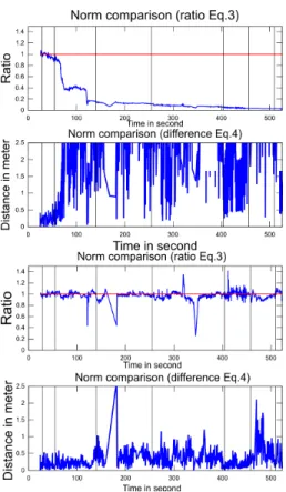
We refer to position error as ||Ct− GTt||2(2). The
inter-camera ratio is computed as ||Ct−1−Ct||2
||GTt−1−GTt||2 (3).
This is the local value of the estimated scale in the re-construction. This ratio is useful to visualize the scale error. However it does not inform on the real error since we can make a large error in percentage on a small quantity but the real difference could stay small. For this reason, we add a third information: the difference of norms ||Ct−1− Ct||2− ||GTt−1− GTt||2(4).
Synthetic results The synthetic sequence is a corri-dor with textured walls generated by 3D Studio Max. This sequence of 2900 frames is 365m long with a 1m/s camera speed. A virtual odometer is generated from the ground truth to test the method; the camera inter-nal parameters and the ground truth are exactly known; the odometer is noise free. Fig. 3 shows the ground truth, the trajectory of the original method (pure vi-sual SLAM) and the trajectory of the improved method (using odometry). We see that the improved method closes the loop with near no error (the original method does not). Furthermore, the localization error of the im-proved method is at most 4m against about 20m for the original one (Fig. 2). Fig. 1 shows that our method cor-rects the existing scale factor drift and that the local er-ror is greatly reduced.
Real results Fig. 4 shows images(640*480) of the se-quence taken in standard urban traffic and driving con-dition (50 km/h) with a calibrated camera, mounted on the car. The ground truth is given by a trajectometer and we use the standard odometer of the car. Fig. 7 provides a top view of the three trajectories (ground truth, orig-inal method, improved method) in the same coordinate frame. This 4 km trajectory confirms the scale drift of the original method.
Fig. 6 and 7 show that the scale factor is close to 1 at any time and the local error remains low thanks to the improved method. The loop closure error on this 4 km sequences is 30m and the maximum localization error is 80m (Fig. 5).
We see that the improved method corrects the scale drift and improves localization and reconstruction, even with standard odometer.
Figure 1. Intercamera comparison with Ground Truth on synthetic sequence: original (top), improved (bottom).
Figure 2. Localization error (Eq.2) on the synthetic sequence.
Figure 3. Reconstructions of the synthetic sequence in the same coordinate system.
Figure 4. images of the real sequence.
Figure 5. Localization Error (Eq.2) on the real sequence.
Figure 6. Intercamera comparison with Ground Truth on real sequence: original (top), improved (bottom).
5
Conclusion and future work
In this article, we demonstrate the usage of an odometer with the LBA-based monocular visual SLAM. Odometry re-scales the pose of a new key-frame, this improves the list of new 3D points involved by this key-frame and the LBA result. Experiments on both synthetic and real sequences show that our method greatly improves the original method by stabilizing the scale factor and providing more accurate result. Since the final result is the output of successive LBAs only applied on image features, the pose covariance may be estimated in real-time with the method [4]. The use of odometry covariance for both visual SLAM and pose covariance in the context of LBA-based monocular vi-sual SLAM is still the topic of future work.
References
[1] H. Bay, T. Tuytelaars, and L. Van Gool. Surf: Speeded up robust features. In ECCV’06.
[2] A. Cumani, S. Denasi, A. Guiducci, and G. Quaglia. Integrating monocular vision and odometry for SLAM. WSEAS Transactions on Computers.
Figure 7. Top reconstructions of the real sequence.
[3] A. Davison. Real-time simultaneous localisation and mapping with a single camera. In ICCV’03.
[4] A. Eudes and M. Lhuillier. Error propagations for local bundle adjustment. In CVPR’09.
[5] M. Fischler and R. Bolles. Random sample consensus. Communication of the ACM, 24(6), 1981.
[6] R. Haralick, C. Lee, K. Ottenberg, and M. Nolle. Re-view and analysis of solutions of the three point per-spective pose estimation problem. IJCV, 1994. [7] C. Harris and M. Stephens. A combined corner and edge
detector. In Alvey Vision Conference, 1988.
[8] P. Lothe, S. Bourgeois, E. Royer, M. Dhome, and S. N. Collette. Real-Time Vehicle Global Localisation with a Single Camera in Dense Urban Areas. In CVPR’2010. [9] E. Mouragnon, M. Lhuillier, M. Dhome, F. Dekeyser,
and P. Sayd. Real time localization and 3d reconstruc-tion. In CVPR’06.
[10] D. Scaramuzza, F. Fraundorfer, M. Pollefeys, R. Sieg-wart, and E. Zurich. Absolute scale in structure from motion from a single vehicle mounted camera by ex-ploiting nonholonomic constraints. In ICCV 2009. [11] B. Triggs, P. McLauchlan, R. Hartley, and A.
Fitzgib-bon. Bundle adjustment-a modern synthesis. In Vision Algorithm: Theory and Practice, 1999.