Demonstration and Evaluation of Co-channel
DBPSK Source Separation
by
Grace R Woo
Submitted to the Department of Media Arts and Science
in partial fulfillment of the requirements for the degree of
Master of Science in Media Arts and Science
at the
MASSACHUSETTS INSTITUTE OF TECHNOLOGY
June 2007
@
Massachusetts Institute of Technology 2007. All rights reserved.
A uthor ...
...
Department of Media Arts and Science
May 18, 2007
C ertified by ...
...
Andy Lippman
Principal Research Scientist of Media Arts and Science
Thesis Supervisor
A ccepted by ....
...
Andy Lippman
Chairman, Department Committee on Graduate Students
MASSACHUSTS INSTITUTE OF TECHNOLOGy
OCT 05 2007
m
ROTCH
Demonstration and Evaluation of Co-channel
DBPSK Source Separation
Date of Submission: May 17, 2007
THESIS ADVISOR: Andy Lippman
Principal Research Scientist of Media Arts and Sciences MIT edia Lab
SIGNED:
THESIS READER: David P. Reed
Adjunct Professor of Media Arts and Sciences MIT/
SIGNED:
THESIS READER: Dina Katabi
Assistant Professor of Electrical Engineering and Computer Science Computer Science. and, Artificial Intelligence Laboratory
SIGNED:
Demonstration and Evaluation of Co-channel DBPSK Source
Separation
by
Grace R Woo
Submitted to the Department of Media Arts and Science on May 18, 2007, in partial fulfillment of the
requirements for the degree of
Master of Science in Media Arts and Science
Abstract
This thesis presents a Differential Binary Phase Shift Key (DBPSK) source separa-tion system implemented with the GNU Software Defined Radio (SDR) platform and interfaced with the existing MIT community Radio Frequency Identification (RFID) system. Source separation, well studied in the theoretical signal processing setting, presents an opportunity to achieve higher throughput in a practical SDR deployment. While much research has centered around the design of complex multi-input-multi-output (MIMO) and code division multiple access (CDMA) systems, single antenna source separation presents a simple alternative that is suitable in settings such as RFID where sources are naturally synchronized. Motivated by the analysis of phys-ical channel properties with GNU SDR, this thesis documents the complete design process from the physical layer to the application layer and presents a realization of a co-channel DBPSK source separating technique. The result is an intelligent RFID source-separating reader that is capable of decoding multiple "dumb" cards.
Thesis Supervisor: Andy Lippman
Acknowledgments
Thanks to my advisors Andy and David for their ideas, guidance and incredible
sup-port.
Thanks again to my readers Andy, David and Dina for their comments and
over-all advice.
Thanks to my family for their love and support.
me be her Xi Gua.
Thanks to my labmates:
Thanks to Dong Gua for letting
Dawei, Unkle Kwan, Hector, Pol, Nadav, Fulu, Durga,
Vyzo, Sung and Illia for their humor and stories followed by qualming technical
ad-vice.
Thanks to all the friends who are partners in mischief.
Contents
1 Introduction
11
1.1 M otivation . . . .
11
2 Background
15
2.1 RFID@MIT ...
...
..
15
2.2 SD R . . . .
16
2.3 Co-Channel Source Separation ...
18
2.4 Design Principle Overview . . . .
20
3 Analysis of Classical Receiver Design
23
3.1
Phase Locked Loop . . . .
24
3.2 Tim ing Recovery . . . .
25
3.3 Differential Decoding . . . .
26
3.4 Crosslayer Design . . . .
28
4 Co-channel DBPSK Card Reader Implementation
29
4.1 Design for Commodity MIT RFID . . . .
29
4.2 Phase Locked Costas Loop . . . .
31
4.3 Mueller and Muller Timing Recovery . . . .
32
4.4 Soft Decoding . . . .
36
5 Evaluation
39
5.1
Basic RFID Antenna Performance . . . .
39
5.3 Probability of Error and Achievable Capacity . . . . 40
6 Conclusion 45
6.0.1 Future Work... . . . . . . . 46
List of Figures
1-1 Hidden Terminal Problem . . . .
12
2-1 Received Signal M odel . . . .
18
3-1 Traditional Receive Block Diagram . . . .
23
4-1 High Level Block Diagram of Source Separating Receiver . . . .
29
4-2 Simple Supplemental Amplifier Powered with 9 Volt Battery Designed
for GNU Radio (SMA connection) . . . .
30
4-3 FFT response with basic coil antennas (See Appendix) . . . .
31
4-4 FFT response with amplifier antenna design . . . .
32
4-5 Frequency Response of Recorded Signal . . . .
33
4-6 Channel Filtered Signal . . . .
34
4-7 Single Card Broadcast Costas Loop Result . . . .
34
4-8 Dual Card Broadcast Costas Loop Result . . . .
35
4-9 Mueller and Muller timing example (with one sample per symbol)
.
.
35
4-10 Constellation Snapshot for 2 source BPSK . . . .
37
5-1 Percentage of Received Packets vs. Distance . . . .
40
5-2 Constellation Snapshots of Amplitude Tracking Result for 80 buffered
samples and average over 20 extremes . . . .
41
5-3 Histogram of Amplitude Tracking Result for 80 buffered samples and
average over 20 extremes . . . .
41
5-4 Figure 14.17 from Cover and Thomas' Elements of Information Theory
6-1 High Level Block Diagram of Modified System for EPIA ITX boards 45
A-1 Fabricated Transceiver Coil Antennas . . . . 48
A-2 Physical Setup of ID cards... . . . . . . . . ... 49
Chapter 1
Introduction
1.1
Motivation
This study and implementation of DBPSK source separation is done to demonstrate that it is practical to rethink interference in the context of modern software radio communication networks.
All the way up until 1899, Guglielmo Marconi had a monopoly on the radio wireless
system. At that time, the wireless industry was used for transmitting race results in the United States. In 1900, Lee De Forest challenged Marconi's wireless betting system. Much to Marconi and De Forest's embarrassment, both systems failed due to interference [30]. As a result, five minute intervals were allocated to allow both Lee De Forest and Marconi's engineers to communicate alternately. A century later, the method of time allocation still dominates most solutions to interference at the receiver.
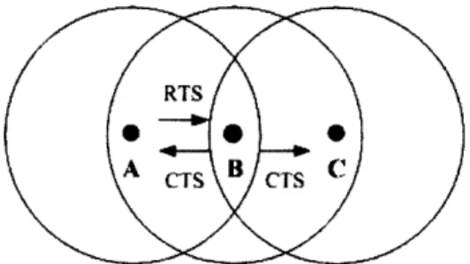
For example, the majority of today's radio systems and networks have been built with the perception that there is a problem of interference. The classic computer network views two packets arriving at the same node as a collision. In the context of many wireless communication networks, the "hidden terminal" scenario has been identified (Figure 1-1) where node B is in the middle of nodes A and C. That is, node
A transmits a request-to-send to node B (which node C can not hear) and node B
Figure 1-1: Hidden Terminal Problem
C both begin to send resulting in a perceived "collision" at node B. Most protocols
are designed around this perceived problem. In reality, the "collision" observed at
node B might contain enough information to deduce the messages of both A and C.
Similarly, in the case of radio frequency identification (RFID), the common use of
hardware card readers has resulted in a perception that only one card may be read
at a time. In the practical case where there is more than one RFID access card in a
single wallet, a common experience that users share is the failure to detect the desired
access card. This experience is largely due to the classical perception of interference
in the design of RFID card readers.
The current approach generally uses time division multiplexing and frequency
divi-sion multiplexing techniques. Here, time dividivi-sion is induced by incorporating multiple
sources that mutually induce timing backoffs in order to result in time-spaced packets.
While this approach is effective in solving the problem of interference, the method
requires careful hardware design of the ID cards themselves. An alternative approach
simply allocates different frequencies to different sources. While this approach is very
effective, current regulation discourages the liberal use of frequency channels. This
thesis uses the RFID card reader setting with multiple cards to demonstrate a system
that is able to overcome the traditional views of interference.
By jointly detecting multiple sources, the problems caused by multiple card
inter-ference is eliminated. By reading two sources on the same frequency simultaneously,
the first generally used approach of specially designed ID cards is no longer necessary.
Furthermore, by using a single frequency rather than dividing through multiple
fre-quencies, the overall throughput of the system is increased greatly. Finally, the use
of a single antenna results in a relatively simple system that requires simple receiver
design.
In order to address the design challenge of a source-separating RFID system, it is
necessary to observe basic properties of the RFID system. The underlying principle
for understanding RFID is that a strong sine wave originating from the RFID reader
is necessary to power the ID cards. The basic observation that the same sine wave
is used for both of the cards results in two signals that are naturally synchronized in
time. That is, the close-range nature of the RFID ID cards result in two channels
that are very close in nature that have a very small phase or time shift between them.
Based on these observations, a prototype is designed in order to evaluate these
observations in an actual setting. Although the performance of the system greatly
depends on multiple factors such as antenna design and the existing RFID system,
this thesis considers the use of a basic RFID antenna and the existing MIT RFID
system. The final results show robust performance using two ID cards at the typical
reading range of a single RFID card.
In the remainder of this thesis, Chapter two continues to give background on
the technical aspects of this thesis. Chapter three describes the architecture of the
proposed system and the motivations for the design decisions made. Much of the
existing architecture is determined by the existing work done by the GNU radio
[18, 21] project. This section contains an overview of that existing architecture.
A discussion of existing software radio architectures options is here. Finally, the
architecture of the system presented in this thesis is included. Chapter four discusses
the fabrication process and detailed explanation of each of the algorithms used in the
implementation. The basis for DBPSK source separation of the MIT RFID cards
is included here. Following, algorithms for each of the building blocks is explained
in detail. Chapter five describes test statistics and test scripts used. Chapter six
describes applications and immediate uses of this system as presented in the MIT
Media Lab. It also discusses future work and possible expansions to this work.
Chapter 2
Background
When two ID cards both become excited with the power carrier waveform emanating from the card reader, a superimposed signal is returned to the card reader to be decoded. As a result, engineers have taken to solutions involving signal suppression or secondary ID cancellation. While these techniques may be practically worthwhile, this thesis considers the exact opposite approach and considers decoding both "interfering" signals with the use of software defined radio (SDR).
2.1
RFID @ MIT
The basic concept behind the passive RFID tag is the modulation and reflection of incident radio waves. The idea is that an incident carrier wave from the card reader is enough to power up an integrated circuit within the card and transmit a response that is embedded with information. The card is typically known as a transponder and has an antenna which is able to both receive the carrier waveform and transmit the modulated waveform back to the card reader.
The existing MIT RFID infrastructure is based on the Indala [22] proximity card system. Currently, they are used for a variety of applications on the MIT campus including means for access and means for storing money. A comprehensive study of the MIT ID card system was done in Fall 04 [20]. The existing infrastructure of the
and facilities throughout the day. Correspondingly, the RF cards might be used for tracking reasons.
The cards used in this system are passively burned RFID cards. That is, the cards themselves do not carry a power source. In order to activate the cards, a 125kHz sine wave source is necessary. Once the minute signal source impinges on the card, the modulated waveform is backscattered back to the reader. The MIT ID card standard is not open. Unlike many other passive cards that might have small electrically erasable programmable read only memory (EEPROM), the MIT ID card does not appear to have this.
One of the major concerns on campus from students and faculty is the security of the RFID technology and the policy of the system in storing information. A
byproduct of this thesis is creating an active RFID tag with the GNU SDR platform and a robust card reader with the GNU SDR platform. Although this byproduct is not technically novel, a replication of the entire MIT RFID system should raise new concern about the potential security and applications of SDR and RFID. A new point to consider is the benefit of SDR receiver-centric design that might prove more withstanding to changing devices and security concerns.
Finally, the system presented in this thesis should give rise to new sensing appli-cations with existing technology. This system might be used to count the number of people in a room. Two SDR readers might be configured to count the time it takes for a person to walk a certain distance on campus by incorporating a time stamp to the ID. A wallet with multiple ID cards might not be surpressed but decoded as well. The existence of a SDR reader also implies quick reconfiguration with new devices on campus.
2.2
SDR
The dawn of SDR in the 1990s has resulted in systems that can be easily built and rebuilt. The term cognitive radio has been devised as a result of being able to easily "listen and talk" without big changes in hardware. As a result, the same SDR may be
used for a communication network as well as a RFID reader. The primary motivation
behind the cognitive radio is to sense the topology and then reconfigure based on
this information. In this thesis, the intelligent radio is "taught" to understand the
modulation for a particular standard. With this understanding, the radio is then able
to perform source separation with a single antenna and a relatively simple algorithm.
With source separation as a design option, new network protocols considering
modified collision principles should be considered. The design of a very intelligent
receiver results in quick interfacing to commodity transmitters and transceivers.
The software radio architecture chosen for this thesis is the GNU platform. A
number of different platforms currently exist for the research community. A number
of these began in the late nineties at MIT. Of these, a few common points characterize
these platforms as software defined radio as summarized by Mitola [15, 16]. That is,
a SDR is in general defined to be comprised of a power supply, an antenna, a radio
frequency (RF) frontend and a multipurpose processor on board. SDRs have been
around for a long time. However, Mitola makes a strong distinction between a radio
that is controlled by software and a radio that is completely reconfigurable in software.
Naturally, this thesis is interested in techniques for the latter.
The general architecture for channel access as summarized by Mitola [15] follows a
flow of the signal impinging on the antenna, followed by RF conversion, intermediate
frequency (IF) processing, baseband processing and finally bit processing. The
tradi-tional source-channel separation applies here as most of the channel access portion is
made available in software. In 1995, Mitola pointed out the differences in analyzing
interference cancellation capacity even for a specific antenna configuration. The
top-ics discussed here continue to explore the quick-prototyping opportunities that GNU
SDR presents.
The GNU SDR software suite is currently being developed to work with the
univer-sal software radio peripheral (USRP) designed by Matt Ettus [21]. The version of the
USRP used in this thesis contain four 12-bit analog-to-digital converters that operate
at 64M samples/second. Correspondingly, the USRP contains four 128M samples/sec
digital-to-analog converters. The USRP interfaces with the PC via a USB bus which
s 1(t) - - h1t
)lt+ r(t)
s2(t) h2(t)
t
n(t)
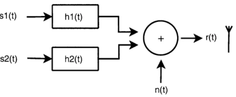
Figure 2-1: Received Signal Model
ultimately becomes the limiting factor. Typically, the onboard firmware is configured to handle 16-bit real and complex component samples. The 32M byte/sec USB in-terface 8M complex samples/sec effectively offering 6MHz of baseband bandwidth. The USRP is currently still being developed and may eventually be upgraded to use a PCI interface for more baseband bandwidth.
The software radio architecture allows for offline processing of recorded waveforms as well as online processing of incoming waveforms. Upon this thesis, a collection of both matlab analysis code and python-c++ hybrid code is available.
2.3
Co-Channel Source Separation
The purpose of this work is to present a starting point for considering co-channel source separation in the context of higher-layer applications. The hypothesis is that a successful implementation of Differential Binary Phase Shift Keying (DBPSK) source separation may be used in receiver design to greatly increase the wireless throughput. In order to demonstrate the immediate benefits of DBPSK co-channel source separa-tion at the user level, this thesis documents a demonstrasepara-tion of decoding two DBPSK modulated MIT ID card waveforms at the same time with a system implemented on the GNU SDR platform. A basic model of the impinging signal at the antenna is shown in Figure 2-1.
About a decade ago, the co-channel source separation problem with one receiver was an active area of research [6, 1, 5, 281. These works summarize theoretical results for modeling two modulated signals in the same channel using Maximum Likelihood
(ML) techniques. Many of these works also analyze the channel interference due to two sources and compare the result to the Gaussian approximation. Torkkola [28] established that it is conceivable to use signal source separation in communication design. Giorgetti and Chiani [4] establish a more realistic model by incorporating fading and channel characteristics. Many of these theoretical techniques require an accurate channel estimation algorithm which may not be ideal for use with the GNU SDR platform.
Recently, some works have resurfaced that suggest algorithms suitable for im-plementation. Of these, a class of phase-tracking algorithms related to the classical Viterbi algorithm has emerged [8, 10]. Hamkins' algorithm [8] has been implemented and evaluated with real world frequency modulated (FM) signals. In this approach,
two signals r, [n] and r .
[n],
regardless of their modulation, may be modeled in thebaseband as:
rr[n] A[nje[]
r[[n] = B[n]ec "[n]
Here, the possibilities O[n] -
#[n]
are solved for geometrically using the additional observable result r[n] = r.[n] + rw[n]. This is done by expanding ||r[n]|| and making preliminary assumptions about the amplitudes A and B. Hamkins uses modified classic algorithms to track the discrete number of phases and also makes intelligent guesses of A and B before decoding both signals with significant reliability. One drawback to the methods proposed by Hamkins, however, is the performance for two impinging signals with comparable signal strengths. Here, the method suffers from a condition called signal switching, where the phase tracking locks on to signal r[n] rather than r,[n]. Under these drawbacks, it is important to consider the context of using signal source separation.Another class of algorithms are known as the demod-remod techniques [7, 19]. Here, the two incoming signals are exactly represented as in Figure 2-1. Specifically,
[7, 19] focus on signals that are roughly 6dB apart. Their simulations with artificially
summed signals showed significant results when the primary to secondary signal power ratio of 3dB. Although these papers do not propose a complete system for using these techniques, they provide a good starting point for working with real-life recorded signals.
A number of works have been done related to RFID devices. One group of works
is interested in suppressing unwanted sources in the same frequency range [25, 11]. These works generally treat an unwanted source as noise and use methods analogous to equalization to suppress the unwanted source. The motivation for this class of works usually include privacy and security concerns. Another class of works have looked at creating special devices that are able to intelligently delay themselves in order to be read at different times [9, 11]. Only a very few number of works are concerned about using existing passive devices that might be decoded using a very intelligent receiver [14]. This thesis presents a design approach to solving this appli-cation level problem.
GNU Software Defined Radio (SDR) provides an optimum testbed for
experi-menting with these new techniques. GNU SDR takes what is traditionally done in hardware and brings it into software. That is, each transmitter is equipped with soft-ware handling up until right before the Digital to Analog converter. Likewise, each receiver is developed in software immediately after Analog to Digital sampling. This software handling opens an entirely new window of opportunities [2] for cross-layer design and algorithms that can achieve significantly higher user wireless throughput. In this thesis, the GNU hardware platform is chosen for its openness and years of development.
2.4
Design Principle Overview
Analysis of cross-layer design such as that used in this thesis has been discussed in many wireless communication contexts [29, 12]. Kawadia and Kumar warn of spaghetti design and cite several examples where well-defined architecture has allowed
for abstraction and solid design. At the same time, leaders in their respective fields
have called for the embracing of SDR architectures. This thesis explores the use of
SDR and suggests that cross-layer design is a safe design method when using software
in a receiver-centric approach.
The primary approach presented in this thesis is to use the known headers of a
particular identification sequence and use it to synchronize the two impinging RFID
signals. In a networking context, this approach might be used to synchronize two
packets. In a deployed version of a source-separating RFID reader, one might consider
using similar cross-layer techniques to determine a change in the number of sources.
The general viewpoint in this thesis is that traditional abstraction layers may be
broken with the onset of SDR. Through testing and fabrication, it is suggested that
loops and bugs which are found may be easily repaired. Finally, the use of cross-layer
design in wireless networks might improve throughput dramatically when a particular
system is designed with a specific application in mind.
Related to the topic of cross-layer design, this thesis explores the benefits of soft
decoding. In an application such as reading multiple RFID encoded devices, there
is little worry of the many obstacles that plague wireless communications. As a
result, using soft decoding without channel estimation is a feasible method of blindly
separating two sources. Following, the practical work done in this thesis presents an
alternative view towards interference in the traditional network. Soft decoding might
deserve a closer look in this context.
In the context of RFID, where the suffered phase shift and timing delay is
rela-tively insignificant, there is a similarity between the amplitude tracking of the signal
source separation problem and the discrete alphabet modelling of an incoming source.
The soft decoding method is based on the assumption of the existence of a discrete
alphabet. On these assumptions, analysis of the probabilities of error may be drawn.
In a complete analysis of the probability of error, higher-layer techniques using
averages across several retransmissions should be considered. A large number of
techniques might be chosen. In the simplest case, several packets might be summed
and averaged according to the hamming distance. A more complex scheme might
involve predictions based on the previous involvement with a particular receive node.
Under such cross-layer techniques, the probability of error might drop considerably
with little trade off.
Chapter 3
Analysis of Classical Receiver
Design
The starting point of the design in this thesis is modelled after a traditional receiver
flow diagram such as the one shown in Figure 3-1. The final design presented in this
thesis is the result of traditional communication design principles and the specific
properties of the proposed application. The basic receiver design in this system is
limited by the existing architecture of the GNU Software Defined Radio platform.
In the traditional flow diagram of Figure 3-1, the purpose of the channel filter
in the GNU radio architecture is to bring the received signal into baseband. In
traditional radio design, the carrier frequency is mixed with the frequency estimate
fc
at the receiver and then lowpassed to the center frequency. The main consideration
here is the number of taps used in the filter of this block and the corresponding
computational time of a multiply and add process. One of the advantages of the digital
communication system and SDR is the use of a larger number of taps. Following this
block, an estimation based detector is needed to adjust the frequency offset and phase
Firel 3-1re
C lock Di ntial
Slicer
difference if significant.
It is generally agreed that the most critical blocks in a receiver are the phase locked loop (PLL) and the timing recovery block. As a result, an overview of traditional PLLs and Timing Recovery blocks is given here before presenting the thoughts that went into designing the dual-card RFID receiver in this thesis.
3.1
Phase Locked Loop
The PLL is often considered the most integral part of designing a good coherent receiver. In decoding the typical DBPSK signal, it is actually unnecessary to have a PLL. However, in extending the method proposed in this thesis to higher orders, the PLL is essential. For this reason, a discussion of traditional PLLs entails here.
The general purpose of the phase locked loop is to make up for a difference between a transmitted waveform and a received waveform. If the path between the transmitter and the receiver were ideal, there would be no need to recover the frequency and the phase (known as carrier recovery). If the oscillator at the receiver were calibrated exactly to the oscillator at the transmitter, there would also be no need for frequency and phase recovery. However, in a practical system, all these problems exist.
One of the methods to bypass the carrier recovery is to use an encoding scheme that does not require correct phase and frequency. DBPSK is actually an example of one of these schemes. However, as discussed in the last section on differential encoding and decoding, non-differential decoding gives a slightly better probability of error. As a result, it is interesting to consider both a coherent system with a PLL and a non-coherent system with no PLL.
The most straightforward way to consider the phase and frequency is to consider the FFT. The peak of the power spectrum indicates where the most energy is and can simply indicate what the frequency and phase is at that point. Unfortunately, in software, the FFT is an expensive procedure. Hence, there are better ways to consider the phase offset with a number of different optimization functions.
difference between a guess and the actual signal. Another, more popular option is
the phase locked loop. The basic idea behind the PLL is to consider an intial guess
for the received signal. Then, after mixing and filtering to remove the high-frequency
component, the DC component is adjusted by changing the phase shift. The Costas
loop PLL explored in this thesis is one of the most commonly used PLLs.
3.2
Timing Recovery
There are quite a few timing recovery schemes that are available. The purpose of
the timing recovery block is to recover the delay r for the incoming analog signal.
All of these methods use an error cost function to determine the delay
Tthat exists
between the optimum sampling point and the current sampling point. Before making
a decision of the timing block to use in the design of this thesis, a brief overview of
the design options are first given here.
There are a few commonsense starting points for designing a good timing recovery
block. One of these is to look at a source recovery error. That is, it is possible to
look at the difference between a recovered waveform and a known existing waveform.
This, of course, requires the knowledge of a training sequence prior to receiving it.
Another approach is to make an intelligent guess about the possible sequence and
take the closest received sequenced. This is known as cluster variance. Both of these
classes of timing recovery do well in certain cases. However, in the context of source
separation, where the discrete alphabet might not even be known upon receiving a
signal, a method related to maximizing the output of the match filter is likely the
most efficient design decision.
Sethares [26] gives a very concise description of a general formulation to a timing
maximization approach. This is summarized in the following. The objective is to
maximize the power of the incoming signal. This may be modelled using the function
avg{x
2[k]}. That is,
J(-r)
=
avg{X
2[k]}
=
avg{x
2M +
Using a p step-size, the above function may be optimized using the update func-tion:
dJ(r) (3.2)
T[k+1]=r[k]+pI ciT= T.2k
d7
With this general expression, it is possible to make a good approximations later and implement an efficient timing recovery block.
3.3
Differential Decoding
A bit sequence is encoded differentially by:
Yn+1 - Yn ( In+1 (3.3)
Correspondingly, the sequence is decoded differentially at the receiver by:
-n+1
= Yn ( Yn+1 (3.4)
Differential decoding is implemented with the mindset of not requiring a PLL. The simple idea is that by encoding a number of bits differentially, the probability of error may be minimized. In the case of a binary alphabet, this is particularly useful because no PLL is necessary. The drawback to this method is that for every bit that is missed, there will be two incorrectly decoded bits.
The most straightforward way to decode an incoming stream of complex DBPSK encoded sample symbols is to consider rk where rk is the kth received symbol. Here, we may model rk as:
rk = |2c * Ebei*k + nk (3.5)
where
#k
is the phase shift, a is attenuation, Eb is the energy per bit and nk is AWGN noise. The decision device is derived from considering rk * rk+1 where x* denotes theupon the phase shift of the incoming samples, Ok - Ok+1
Fk * rk+1= 2Ebe(k-9
k-1) - 2Ebek n_ - 2Eb-_k- n±- nknk_1 (3.6)
In general, the probability of error for a differential system is quite hard to find. However, the error of probability for a DBPSK system according to the above
expres-sion is generally known to be:
1-Eb
Perror = -e No (37)
2
Here, No generally indicates the ratio of the energy per bit(E) to the noise power
spectral density (NO). Implementing source separation is analogous to determining the alphabet size and then decoding n number of streams separately. In a RFID application, the phase shift for the two sources are nearly the same. This is due to the generated modulated waveform that are synchronized by default. The same 125kHz waveform is modulated by both cards and the time distance between them are negligible due to the small distance between them. Hence, differential decoding may still be implemented without a PLL.
The MIT RFID cards are implemented using DBPSK. It is not clear whether the Indala readers are also implemented differentially. However, using the GNU radio platform, experiments were done using both differential and non-differential decoding with the aid of the Costas PLL. Finally, source separation may also be done both using a BPSK decoding approach and a DBPSK decoding approach. Depending on the channel conditions and the value of -, the probability of error varies.
The decoding design is an integral part of the receiver as it gives rise to the probability of error and the performance of the given system. For a single source, the probability of error in a practical system is quite straightforward. For multiple sources, the probability of error becomes greater as the results of the amplitude track-ing give rise to shifttrack-ing constellation points. Regardless, a method exists for analyztrack-ing the probability of error and considering what the limits of a source separating system
might be.
3.4
Crosslayer Design
With the increase in the number of constellation points, there is an obvious increase to the probability of error. However, with a combination of soft decoding approaches
[29, 12] and packet memory techniques [27, 23], a few interfering sources might still
be decoded using a tailored design approach [24].
Of these methods automatic request protocols [24] are used as a recombination
method with the same theoretical roots as repetition coding. Here, hamming distance may be taken to map the received sequence to the sequence with the least hamming distance. [17] summarizes a few points about methods for recombination. Straight-forward approaches for combining multiple receptions including taking the soft value with the highest confidence or doing a majority vote. These approaches, although counter-intuitive, suggest that not all retransmissions are equal. In the case of RFID, however, where transmission range is fairly short and the channel variance is quite small, it is a safe approximation to consider simple recombination algorithms.
Chapter 4
Co-channel DBPSK Card Reader
Implementation
The source separating receiver implementation follows as much as possible a tradi-tional receiver design such as that shown in Figure 3-1. The high-level block diagram of the source separating receiver is shown in Figure 4-1. Figure 4-1 is implemented in software with hybrid Python and C++ code and depicts everything after the A/D sampler. The baseband frequency tuning on the GNU SDR gives approximately 6MHz of bandwidth. Hence, there is no need for a carrier-frequency mixing stage prior to decoding.
4.1
Design for Commodity MIT RFID
The waveform which needs to be decoded on the receive end of the antenna may be modelled as a 125kHz carrier wave modulated by a 62.5kHz signal. The symbol rate
of m(t) is 125 4kHz. Hence, in general, the incoming waveform may be modelled
as:
Incoming channel costas Cckr Acpiude Dua Access Code Decoded
Signal 4-1: Loop e Signals
Audio In
5
22K 0.01pF(axia1) Antenna
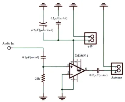
Figure 4-2: Simple Supplemental Amplifier Powered with 9 Volt Battery Designed
for GNU Radio (SMA connection)
s(t) = m(t) cos (27r * 125kHz * t) cos (27r * 62.5kHz * t) (4.1)
where m(t) is a DBPSK encoded square waveform with -kHz frequency. The Indala
reader does not necessarily read the card in the way that this thesis presents. However,
with the above assumption for the format of the incoming waveform, a consistent
reading is available.
From this assumption, we see that a minimum power sine wave cos(27r* 125kHz*t)
must be generated in order for a passive MIT RFID card to be activated. The
GNU SDR comes with a transmitter equipped with an onboard amplifier as well as
a gain in software. With the existing amplifier set to the maximum limit, a basic
supplemental amplifier for the GNU SDR transmitter is still necessary to achieve
the desired gain. The schematic designed specifically for the GNU radio basic TX
transmitter is documented in Figure 4-2.
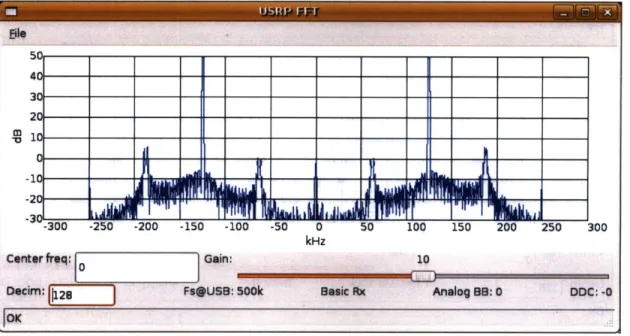
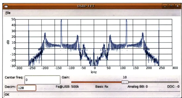
The FFT response prior to the addition of a amplifier is given in Figure 4-3. The
gain acheived by this amplifier and the resulting purity of the signal is documented
Figure 4-3: FFT response with basic coil antennas (See Appendix)
in Figure 4-4.
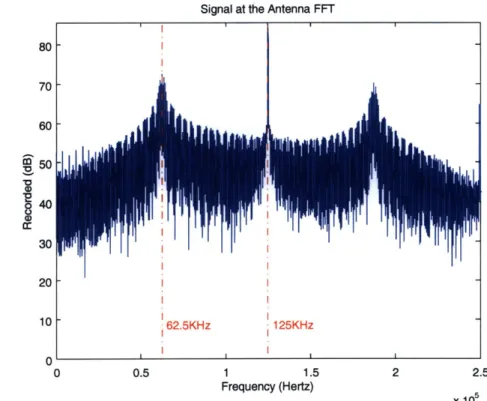
Based on the response of the RFID antennas, a model is considered for the format
of the MIT RFID cards. We consider filtering out the major 125kHz component and
analyzing the 62.5kHz signal. Using the tools developed for this thesis, a response is
generated for the received signal to determine the windowing and coefficients for the
first filter. Figure 4-5 considers the frequency response of the recorded signal.
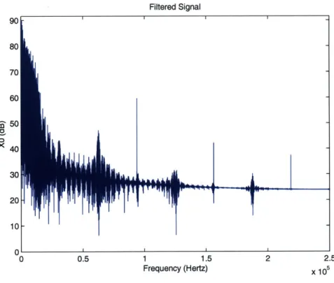
Based on the frequency response of the recorded signal, a channel filter is designed
for the receiver with a cutoff of 30 kHz, a transition bandwidth of 30 kHz and a
Hamming window. The result of the channel filter is documented in Figure 4-6.
4.2
Phase Locked Costas Loop
A PLL is not necessary to decode DBPSK signals. However, with the use of a PLL,
the waveform intended for DBPSK decoding may also be decoded coherently as a
BPSK signal. Furthermore, seeing the visual output of the costas loop gives a great
sense of how source separation using the synchronized soft values might work.
ile
5 40 30-20 10 -10 _ -20 .1 1 -3 10 :__ -- --300 -250 -200 -150 -100 -50 0 50 100 150 200 250 300 kHzCenter freq: Gain: 10
0
0d~cm: 19FsU~LSB: 500k Basic Rx Analog BB,:0 DOC: -0
L[OK
Figure 4-4: FFT response with amplifier antenna design
(VCO) such that the phase error may be kept as close as possible to 0. Much
lit-erature exists for the development and implementation of an effective Costas Loop
[26, 13]. The consideration of this mature work results in the values chosen for this
implementation of the Costas loop. The corrective Costas loop requires the
appro-priate values for parameters a and 3. Here, the parameter a considers the step-size
for the phase and ,3 considers the step-size for the frequency. The proper parameters
for a and 3 in the implementation of RFID are 0.01 and (0.25)(0.01)2 respectively.
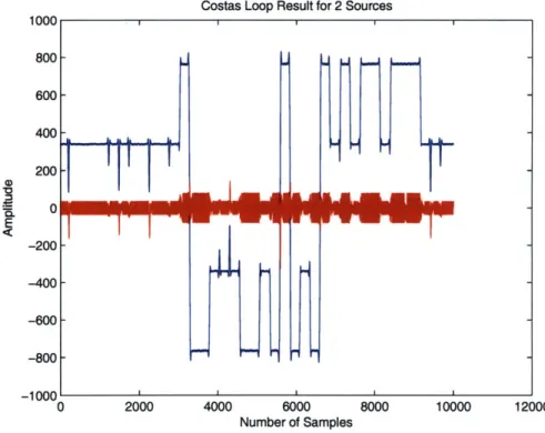
Figure 4-7 documents a typical single card broadcast and Figure 4-8 documents
a typical dual card broadcast. Since the phase for the two impinging signals are the
same.
4.3
Mueller and Muller Timing Recovery
The match filter is a time reversed version h[n
-
k] of the original transmitted pulse
shape. The reason for doing this is rooted in the assumption that the channel is an
additive white Gaussian noise (AWGN) channel. That is, we wish to integrate the
received signal energy while averaging out the zero-mean AWGN. To pass the received
Signal at the Antenna FFT 40 30 20 1 10 62.5KHz 1 1.5 Frequency (Hertz)
Figure 4-5: Frequency Response of
33
Recorded Signal
80 70 60 50I
125KHz 2.5 x 10⁵Filtered Signal
0 0.5 1 1.1f
Frequency (Hertz)
Figure 4-6: Channel Filtered Signal
Costas Loop Result for 1 Source
6000
Number of Samples
Figure 4-7: Single Card Broadcast Costas Loop Result
2.5 x 10,Costas Loop Result for 2 Sources
0 2000 4000 6000 8000 10000 12000
Number of Samples
Figure 4-8: Dual Card Broadcast Costas Loop Result
signal through the filter, we are interested in the convolution y[k]
=I
_% h[n
-k]x[k]. This result y[k] is now sampled at every T to return a floating point binary
sequence (the sequence that we are interested in) that is sent to the decision device.
In order to ensure that the sampling at T returns the value with the highest signal
to noise ratio (SNR), the timing recovery block is necessary. Due to phase shift and
clock drift at the receiver, the sampling frequency and phase will not be perfect due
to the nature of a practical system and the optimal sampling time T will not always
Atime
Fast timing:
e = (-0.8 * 1) - (-1 * 0.5) = -0.3
time Atime
Correct timing: Slow timing:
e = (-1 * 1) - (-1 * 1) = 0 e = (-0.5 * 1) - (-1 * 0.8) = 0.3
yield the best value for decision. The Mueller and Muller algorithm requires only one sample per symbol to determine how the incoming signal might be adjusted so that the sampling point T yields the best possible correlation result.
In order to determine how the incoming sampled signal must be adjusted, the Mueller and Muller algorithm uses a simple error criteria. That is, it considers the error expression: e,
=
(rn * rn_1) - (rn * rn_1). Here,rn_1
is the previously receivedsample and rn is the currently received sample. This corrective approach is quite straightforward and the algorithm buffers until a value closest to en = 0 is achieved.
To clarify the Mueller and Muller approach, Figure 4-9 is provided as an example. The Mueller and Muller timing recovery scheme is quite expensive for a large number of samples per symbol. As a result, in a computationally less expensive implementation of RFID decoding, a decimator may be implented prior to Mueller and Muller timing recovery. One advantage to the Mueller and Muller timing recovery algorithm is that only two samples per symbol are technically required to interpolate and sample at the correct time.
4.4
Soft Decoding
For two possible ID cards, we say that there are two possible bit sequences si ss(1), si(2)...si(k) and length k = 224. The objective of this system is to best estimate si from the received sequence di. That is, we would like to estimate si such that
p(rkls ) 5 P(rIsk )Vk (4.2)
Using joint ML sequence estimation, the above expression may be replaced by a Euclidean distance critera when using a AWGN noise model:
k k
'r()
- s(l)12
!5E
r(l)
-s
2(l)|2Vq
(4.3)
1=0 1=0
An amplitude tracking algorithm is implemented using a sort on the previously received n samples followed by a mean over the lowest values x which give a good
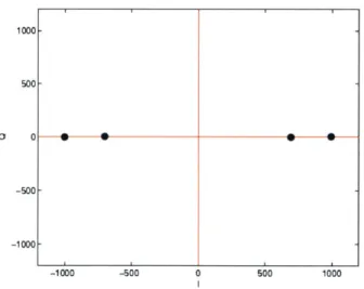
1000 500-0 0 -500 --1000 --1000 -500 0 500 1000
Figure 4-10: Constellation Snapshot for 2 source BPSK
estimate of the amplitude A
-
B and the highest values x which give a good estimate
of the amplitude A + B. Based on this, a one dimensional constellation for
two-source BPSK two-sources is updated with every incoming sample. An example of a
one-dimensional constellation is shown in Figure 4-10.
For two sources, there are 4 constellation points in each snapshot. For n number
of sources, the would be 2" number of one-dimensional constellation configurations.
For each additional source, the probability of error increases dramatically. However,
with the use of additional coding and packet memory techniques, a robust system
may still be achieved.
Chapter 5
Evaluation
The system design presented in this thesis is robust with near perfect performance for two sources given a physical setup such as that documented in the Appendix. In this setup, the cards placed in any fashion on the platform.
5.1
Basic RFID Antenna Performance
The correctly received packets follow a distribution according to Figure 5-1. The figure documents the percentages for 1000 packets sent. This packets-received to distance relationship statistic essentially reflects exactly the extended hidden terminal formulation in Figure 1-1 where there is a sharp cutoff for the region where cards may no longer be decoded.
5.2
Amplitude
T
lracking
Given the receive design proposed in Chapter 3, there are a number of tradeoffs present in the various blocks of the diagram. One of the major determinants of performance are the parameters used in the amplitude tracking stage. Although the most intuitive methods for amplitude tracking is to use an overall mean, the best performing is to keep a history of N number of samples and take averages over the extremes.
Evaluation of RFID Reader 0.9-n 0.8-CO cL 0.7-
0.6-$
0.5-0 2 0.4-.3 C 0 = 0.3 0 a- 0.2-0.1 -0 0 0 0 0 5 10 15Distance Away from Antenna (cm)
Figure 5-1: Percentage of Received Packets vs. Distance
Figure 5-2 shows uniform snapshots of the dynamic constellation over time for a
buffer size of 80 and averaging of extermes over 20 values. This is one of the best
performing configurations. Figure 5-3 documents the result of the same amplitude
tracking data as in Figure 5-2.
In a further modified version of the code where the GNU radio architecture is
modified slightly to accommodate a large number of sampled buffers, an update is
made every 10000 number of incoming samples.
5.3
Probability of Error and Achievable Capacity
The probability of error analysis for the proposed system is complex due to the
chang-ing constellation. The probability of error for a schang-ingle time slot may be considered
by using the instantaneous constellation configuration and a AWGN model.
Follow-ing, the constellation may be modified as desired. A traditional probability of error
analysis may be done for every constellation that is regenerated.
Amplitude Tracking 1500
1000
- 500-)0 -1000 -500 0 Real Axis 500 1000 1500Figure 5-2: Constellation Snapshots of Amplitude Tracking
samples and average over 20 extremes
X 104 Amplitude Tracking
Result for 80 buffered
-1500 -1000 -500 0 500
Constellation Point Distribution
1000 1500
Figure 5-3: Histogram of Amplitude Tracking Result for 80 buffered samples and
average over 20 extremes
x x x X X 15c X X
-x
1
-1500' -1501L
I I I I I 500 1000-channel model used is an AWGN model. Here, we may use the results summarized
by Cover and Thomas
[3]
to understand the achievable rate in a system such as the one presented in this thesis. If we define the capacity of a channel to be:C(x) = - log(1 + x) (5.1)
2
when the channel is modelled as an Additive White Gaussian Noise (AWGN) channel with variance N. Then, the known classical result is that the rate of the first source, R1, must follow the relationship R1 C(P/N) where Pi is the power
of the first source. Likewise, the rate of the second source, R2, must follow the same
relationship R2
< C(P
2/N)
where P2 is the power of the second source. Due tosuperposition, the relationship:
RN+
R2 < C( P(5.2)
N
must hold. The important conclusion from this defintion of capacitiy of two sources with power levels P1 and P2 is that it has the same capacity of a system with the power P1
+
P2. Furthermore, if there is consideration for a case when P1 and P2are the same but the frequency bandwidths W = W1 + W2 are varied. Here, using
the classical definition of rates, the rates R1 and R2 may be modelled as:
R1 =
log
I +N
)
(5.3)N
NW1
W1421(
P
2R2
N
log 1 +
N
NW2
2(5.4)
Based on this definition, W1 and W2 may be varied as is done in frequency divisionmultiplexing. Figure 5-4 summarizes these results. There are
In Figure 5-4, the bottom curve traces out the achieved capacity using a frequency division multiplexing scheme. The upper curve traces out the fundamentally achiev-able capacity. The theoretical gain in capacity achieved using this practical system is interpreted as the small gain towards the corners of the higher curve. These corners are achievable using a subtraction method analogous to the method proposed in this
R
2KNI
C
-P-P, + N)
0pp
C
-- -
C, ---
R
(P2 + N
N--Figure 5-4: N--Figure 14.17
[3]
from Cover and Thomas' Elements of Information Theory
thesis. That is, the first signal may be decoded treating the second signal as noise.
Then, the result is subtracted and the second signal is decoded treating the first signal
as noise. The numerical results of the built system show that it is practical to have a
highly intelligent receiver that is able to approach the limits of the proposed practical
Chapter 6
Conclusion
The system presented in this thesis demonstrates a few important principles:
" The power of receiver-centric design
" The advantages of software defined radio when used with soft decoding " The power of application-aware physical layer design
" The opportunity for source separation in the presence of interference
The original code for this thesis was implemented on 3.2 GHz Dell Machines. Small modifications with slightly worse performance was written to run on EPIA ITX boards. The major modifications included a cruder channel filter with fewer taps and a decimation block prior to Mueller and Muller timing recovery as shown in the modified block diagram in Figure 6-1.
Incoming Signal
Decoded Signals
The implementation of the receiver on the smaller EPIA Mini ITX boards allows for futher experimentation in the future with the GNU SDR code.
There are a variety of direct application scenarios that apply to this implementa-tion of DBPSK source separaimplementa-tion. At the very least, having multiple ID cards in a wallet need not implying interference if the existing readers are replaced with SDR readers. Furthermore, the introduction of new coding simply implies a change in soft-ware. Furthermore source separation code as and underlying technology may be used to introduce new applications such as the applications demonstrated in May 2007 at the MIT Media Lab.
6.0.1
Future Work
In a version of this system that might actually be deployed, there are a few small modules that must be added. An agent considering the existence of one source versus N number of sources must be implemented. A simple extension for this is to consider a threshold.
Source code and Analysis code for this project are available online at:
Appendix A
Figures
Figure A-1: Fabricated Transceiver Coil Antennas
a
a -
a
Bibliography
[1] M. Chiani. Performance of BPSK and GMSK with multiple cochannel interferers.
In Seventh IEEE International Symposium on Personal, Indoor and Mobile Radio
Communications, October 1996.
[2] D. D. Clark, C. Partridge, R. T. Braden, B. Davie, S. Floyd, V. Jacobson,
D. Katabi, G. Minshall, K. K. Ramakrishnan, T. Roscoe, I. Stoica, J.
Wro-clawski, and L. Zhang. Making the world (of communications) a different place. SIGCOMM Comput. Commun. Rev., 35(3):91-96, 2005.
[3] T. Cover and J. Thomas. Elements of Information Theory. Wiley Series in
Telecommunications, 2 edition, 1991.
[4] A. Giorgetti and M. Chiani. Influence of fading on the gaussian approximation for BPSK and QPSK with asynchronous cochannel interference. IEEE Transactions
on Wireless Communications, 4(2):384-389, March 2005.
[5] K. Giridhar, S. Chari, J. Shynk, and R.P. Gooch. Joint demodulation of
cochan-nel signals using MLSE and MAPSD algorithms. In IEEE International
Confer-ence on Acoustics, Speech and Signal Processing, April 1993.
[6] K. Giridhar, S. Chari, J.J. Shynk, R.P. Gooch, and D.J. Artman. Joint
es-timation algorithms for cochannel signal demodulation. In IEEE Interational
[7] R. Gooch, C. Jorgensen, and M. Ready. The demod-remod technique for
de-modulating co-channel FSK signals. In Conference Record of the Twenty-Fifth
Asilomar Conference on Signals, Systems and Computers, November 1991. [8] J. Hamkins. An analytic technique to separate co-channel FM signals. IEEE
Transactions on Communications, 48(4):543-546, April 2000.
[9] C. Hartmann, P. Hartmann, P. Brown, J. Bellamy, L. Claiborne, and W. Bonner.
Anti-collision methods for global saw rfid tag systems. Ultrasonics Symposium,
2(23-27):805-808, 2004.
[10] G.J.M Janssen. Receiver structure for simultaneous reception of two BPSK
modulated co-channel signals. IEEE Electronics Letters, 29(12):1095-1097, June
1993.
[11] A. Juels. RFID security and privacy: a research survey. IEEE Journal on Selected Areas in Communications, 24(2):381-394, 2006.
[12] V. Kawadia and P.R. Kumar. A cautionary perspective on cross-layer design.
Wireless Communications, IEEE, 2(1):3 - 11, February 2005.
[13] B.P. Lathi. Modern Digital and Analog Communication Systems. Oxford
Uni-versity Press, 3 edition, 1998.
[14] J. Lee, T. Kwon, Y. Choi, S. K. Das, and K. Kim.
[15] J. Mitola. The software radio architecture. IEEE Communications Magazine,
pages 26-39, May 1995.
[16] J. Mitola and G.Q. Maguire. Cognitive radio: Making software radios more
personal. Personal Communications, 6(4):13-18, August 1999.
[17] A. K. Miu, H. Balakrishnan, and C. E. Koksal. Improving Loss Resilience with
Multi-Radio Diversity in Wireless Networks. In 11th ACM MOBICOM