Computers and Video:
Coincidental in Architectural Design
byJanet Elizabeth Gardner
Bachelor of Architecture
Ball State University
Muncie, Indiana
1985
SUBMITTED TO THE DEPARTMENT OF ARCHITECTURE
IN PARTIAL FULFILLMENT OF THE REQUIREMENTS FOR THE
DEGREE
MASTER OF SCIENCE IN ARCHITECTURE STUDIES
MASSACHUSETTS INSTITUTE OF TECHNOLOGY
June 1987
@ Janet Elizabeth Gardner 1987
The Author hereby grants to M.I.T. permission to reproduce and to distribute publicly copies of this thesis document in whole or in part
Signature of Author
Janet Elizabeth Gardner Department of Architecture May 8, 1987
Certified By
James Anderson
\-Jcturer, Department of Architecture Thesis Supervisor
Computers and Video: Coincidental in Architectural Design
By
Janet Elizabeth Gardner
Submitted to the Department of Architecture on May 8, 1987
in partial fulfillment of the requirements for the Degree of
Master of Science in Architecture Studies
ABSTRACT
Architects express abstract concepts in physical concrete realities. The tools of the
trade act as a medium through which to express these concepts; pencil, paper,
models. Yet these tools do not allow for any intelligent discourse. While translating an
abstract idea into a physical object, a designer must keep track of complex
associations between various elements within a design. As an idea becomes further
developed, the associations between elements become more difficult to manage.
On occasion matrices are employed to maintain a consistent relational system, yet
complexity often forces design concepts to get distorted or lost. This thesis provides
one solution; a method for to the management of this barrage of associative
information, while still providing a stimulating design environment.
With the proposed tool, a designer can use numerous media simultaneously; for our
purposes digital video and an object-oriented graphics editor. The video environment
acts as an analysis tool for exploring existing architypes, in search ofinherent themes.
The graphics editor is a tool for synthesizing objects, creating a whole from a series of
parts discovered in the video environment.
The key to this tool is it method for handling objects. Objects have the ability to retain
knowledge, therefore acting as an intelligent adjunct in the design process. The
architect designs with objects. Objects
"know"
what their behavior is, and how to
perform certain operations. Other attributes and relationships can also be attached to
objects, or classes of objects.
Compilation of both environments is possible, due to a central knowledge base that
maintains all the information from all objects. This single knowledge base allows
objects in one environment to be shared by the other, creating an interactive
environment between two independent media, computers and video, therefore
eliminating the bold line that typically separates the two.
Thesis Supervisor: James Anderson
ACKNOWLEDGMENTS
My sincere thanks to the following people:
To my family, for their continued support in all my endeavors, direct and indirect.
To James Anderson, my thesis advisor, for his pointed questions, and his critical help at
important times both in writing and in programming.
To Stephen Ervin for his words of encouragement, who's hours of patience are greatly
appreciated.
To Professor John Habraken, for exposing me to a design methodology that was well
adapted to the exploration of this thesis.
To all those in M.I.T.'s Computer Resource Laboratory past and present, for the
introduction to many new and exciting concepts that lead to this thesis.
To all my friends at M.I.T. that made our stay here an enjoyable educational
experience in and beyond the classroom; especially to Wendy Weeks and Gaius
Nelson.
To Professor Jack Wyman, for his continued interest in my academic experiences.
To Jim and Linda Shirk, for their constant support and encouragement.
To J. Robert Taylor, a special friend that I could always turn to if I needed a word of
encouragement.
TABLE OF CONTENTS
Abstract
page 2
Acknowledgments
page 3
Content
page 4
1) Chapter One - Introduction page 6
General principles introduced
1.1)
Intent
page 7
1.2)
The Model
page 8
1.3)
The Tool
page 9
2) Chapter Two - Overview page 13
Abstraction and synthesis with proposed tool
as applied to the design model
2.1) Intent
page 13
2.11) Abstraction
page 14
2.12) Synthesis
page 16
2.2) The Model
page 18
2.21) Typology
page 18
2.22) Thematic System
page 19
2.23) Structure
page 20
2.24) Hierarchies
page 20
2.25) Classes
page 21
2.26) Space
page 22
2.3) The Tool
page 22
2.4) Summary
page 24
3) Chapter Three - Visual Imagery
page 25
The digital video environment
3.1) Visual Rhetoric
page 25.
3.2) Image Access
page 26
3.3) Visual Abstraction
page 28
3.31) Phase One
page 29
3.32) Phase Two
page 30
3.33) Video Objects
page 33
4) Chapter Four - Graphics Editor page 37
The Object-Oriented Graphics editor
4.1) Role of the Object-Oriented Graphics Editor page 38
4.2) Concept of an Object-Oriented Graphics Editorpp. page 39 4.3) Behavior in an Object-Oriented Environment page 40
4.4) Creation of Objects page 41
4.5) Hierarchies and Classes page 43
4.6) The Design Model Applied page 46
4.7) Footprints of the Design Process page 46
5) Chapter Five - Synergism page 48
The Role of a Central Knowledge Base in compilation
5.1) Windowing Systems page 49
5.2) A Central Knowledge Base page 49
5.3) Objects and Classes in a Knowledge Base
page 51
5.31) Assigning behavior and classes to page 53
objects stored in the knowledge base
5.32) Exchange of Knowledge page 56
5.33) Control of Classes of Objects
page 57
5.4) Footprints in Composition page 57
5.41) Juxtaposition of Footprints in Design page 58
5.42) Footprints as Overlays page 59
5.43) Footprints as Intelligent Adjuncts page 60 5.44) Simulation Using Footprints page 61
5.5) Summary page 62
6) Chapter Six - Design Scenario page 63
7) Chapter Seven - Conclusions page 90
"Our inspirations assist us when we clear our senses of known
solutions and methods. The realization of a yet unthought-of nature
and the elements of its form can stimulate an entirely new point of
view about everything. Today we talk about technology as though
our minds will be surrendered to the machine. Surely the machine
is merely a brain which we get, pot luck, from nature. But a mind
capable of realization can inspire a new technology and humiliate
the current one."
Louis Kahn
INTRODUCTION
Architectural design, like all forms of communication, is based upon a series of signs
and symbols. Through this iconography, a design attains its own vocabulary by which
to represent its image of reality. This image of reality is very subjective and varies
greatly from design to design.
In the design process, knowledge is often represented with diverse media. The
designer is able to optimize his description of intended concepts using the unique and
distinct character of each medium. Whether the media be drawing, models, or
photography, this combination provides the designer with better methods for
describing abstract concepts as concrete objects. Each of these media is a tool
.
New tools are constantly being introduced. Two such tools are the computer and
tool, and the computer, as a design tool will be explored through one prototype in this thesis, which assumes each to be an intellectual adjunct in the design process.
1.1 INTENT
In the past, the use of computers in architecture has centered around production. Today, the exploration of the computer as a tool for architects is emphasizing the design process. In the following, we will explore a new form of computational tool, and its potentials for design: the synthesis of computer graphics and digital visual imagery as means for expressing design knowledge.
This thesis describes an additional communication tool for the designer, and develops a prototypical syntactical structure for its vocabulary, using an established model of design. The intent is to explore the advantages and limitations of using the computer and digital visual imagery concurrently.
The new tool will be used to investigate potentials, and strengthen the understanding of
abstract notions and concepts in the design process. It would be bold to claim that this tool will help all designers to visualize these concepts. However, it will investigate a new
method for both the representation and comprehension of an abstract notion or
concept by bridging the gap between the two, exploring a "seamless carpet of knowledge and learning", capable of in-depth investigation, association, and communication of the designer's own personal vision (Lambert 1986).
The proposed design environment includes a graphics editorand digital video images.
1.2 MODEL
Its is necessary to establish a model of the design process to utilize in a development of this tool. This model will look at design as a systematic approach based on a structured
format of rules and constraints. It uses Prof. John Habraken's Hierachies in Form . This methodology was chosen for two reasons. First, it is a design methodolgy which lends itself well to computational exploration (Habraken 1983). Near the beginning of the design process the designer develops a set of rules and constraints that become the
basis for decision making. Through these rules and constraints a method for analyzing and understanding new and existing environments is developed and a structured format from which to work established. This structured approach aids in the definition of
the problems at hand, assisting in the often ambiguous task of "Problem Solving". The concept of designing with constraints was further explored in a PhD Disseratation by Mark Gross titled "Design as Exploration of Constraints" (Gross 1986). Secondly, Prof. Habraken's methodologies reference the single family dwelling, which shall be the building type to explore.
The concept of Hierarchies in Form is well developed and documented, especially regarding the single family dwelling. This building type is small enough in scale, and yet
complex enough in its potential rules of organization that it will be managable and productive. There is a large body of literature elaborating upon hierarchies and the
single family dwelling, yet the concepts and writings are not limited to this typology
The theory begins at the scale of the urban tissue, and propogates to that of furniture in a room (Habraken 1984), exploring tissue type organization of environmental form.
1.3 THE TOOL
The architect is a visionary, changing abstract concepts into known, and understood
realities. These realities do not exist only in built form: Representations are present in drawings, models, etc. For the designer, an effective communication mode is a
necessity. With the help of various media, architects are able to investigate, design and convey their intentions. The paper and pencil are the conventional tools of the architect for representing intentions for built form. If we were to remove this
representational media, and not replace it with a comparable substitute, our means for expression could be hampered. We therefore conclude that by limiting the tools of the designer we limit the means for expression of abstract concepts, thus limiting the product. Conversely, additional meaningful tools could increase the designers ability to express abstract concepts, improving understanding and thus improve the product.
By introducing an additional tool, we shall add another representational media to aid the designer in the expression of abstract notions. Four primary activities will be available with the introduction of this synergistic tool, which intergrates computer graphics and digital visual imagery into the design process. These activities, visual referencing through a visual database, annotation / sketching, a graphics editor, and compilation of the previous three into a composite image are described below.
Level One - Visual Database
The Visual Database allows the designer to view images based upon a
category, classification, and/or relationship. Images can range from "Master Specifications", to "window details", to a series of images referencing "churches built between 1860 and 1880, by H.H. Richardson in Boston,
myriad of images, their classifications and relationships.
Level Two - Annotation / Sketching
Images are accessed, sorted, and grouped through a classification scheme in
the visual database. Annotation and sketching on top of the image can then
be used to better illustrate the desired elements of the image, and demonstrate inferences being made about each image. This basic sketch and analysis tool
is similar to procedures currently undertaken with a pencil and tracing paper over a
chosen drawing or photo. Beyond the basic options for annotation, the designer can also begin to use the computer to help analyze the image, breaking down the various elements into objects. These objects are then categorized by the designer
and assigned an established class., or the designer can create a new class "on
the fly". These classes are associated with a hierarchy.. and are a relative means
for understanding an image, or building.
A class is composed of objects which contain properties of similarity. Each class is assigned a location in the hierarchical framework. For example, the window is in the wall, and the muttons are in the window which is in the wall. Through this
example we can begin to understand classes (walls, windows, muttons) and hierarchies (window in wall, mutton in window, etc) with regard to physical location.
Classes are not limited to physical similarities. They can also be grouped by conceptual, or behavior attributes. For example, by manipulating class.X, it causes
objects A and B to change color from BLUE and GREEN respectively to RED. This physical change in objects A and B occurs due to their binding to class X, which is
of a higher-level in the hierarchy. Therefore, A and B may be categorized in the same class due to their similar behavioral attributes.
With a hierarchy in place, the search process which occurs on a large scale in the
visual database can be applied to; each individual image, clusters of objects
which may form a class within that image, or a series of images. Therefore, we can query for information within an image just as we queryed for information across multipule images in the visual database. For example, we could query for all the RED objects within an image, and have them displayed in a specified location, implimenting a similar search as that which occurred previously.
Architects do not design line by line, vector by vector. They recognize volumns, sythesizing wholes from parts to give embodiment to their design concepts. In order to adaquately express these concepts, representational tools
should conform to these ideals. Establishing a class structure within a hierarchical framework allows the designer to recognize objects, whereby an image becomes
a series of objects that describes its inherent vocabulary. This vocabulary, constitutes a method of communication and analysis more directly
associated with the process of designing.
Level Three - Graphics Editor
The Annotation / Sketching level is primarily a subtractive process. The designer is
given a complex image, and through analysis elminates the non-essential
elements to derive the representation most appropriate for expressing themes and structure within a chosen building type. The Graphics Editor acts as an electronic
instead of primary elements such as lines. With the editor, the process is one of addition and synthesis. A theme which has been discovered or created, with the help of the typology investigation, is abstracted through transformation. The result in many cases is a more complex object, composed of smaller elements and
expressing a desired theme. Class systems can be associated with the objects in a similar fashion as in the Annotation / Sketching level, further elaborating on design
as an object oriented process.
In addition to assigning a class to each object, the designer can begin to attribute behavior to objects. This ability to assign behavior introduces objects, and classes of objects, as intellegent adjuncts in the design process, aware of what actions they can and can not perform.
Level Four - Synergism
Composition of the aformentioned tools creates a forth level. At this level the designer extracts important elements and phases in the analysis and synthesis process in search of information not attainable by either tool independently.
Juxtaposition of these stages against one another is a visual referencing tool, similar
to comparing a design of a prairie style house with a house of Frank Lloyd Wright's. With elements in an image capable of retaining knowledge and behavioral characteristics the combination of objects from either tool can lead to more than a visual reference. Composition could suggest the effects that actions taken on an
object in one environment have upon a similar object in another: Therefore extending the current use of either digital video or the computer beyond their
I have no chair, nor church, nor philosophy
/ lead no man to the dinner table or library or exchange.
But each man and each woman of you I lead upon a knoll,
My left hand hooks you around the waist,
My right hand points to landscapes of continents,
and plain public roads.
Not I nor anyone else can travel that road for you, You must travel it for yourself.
Walt Whitman
CHAPTER TWO
21 INTENT
The physical environment encompasses complex configurations of elements.
Designers manipulate these physical elements in order to discover the desired configuration best representing their abstract concepts. These abstract concepts are often difficult to represent in concrete physical elements. Each designer visualizes
certain things in certain ways, expounding upon various concepts, and experimenting to discover the physical configuration that can best begin to describe the abstract
concepts known only to herself. The subject of exploration will be such abstract concepts, concretized to manifest themselves in the built environment, and the methods for expressing and understanding them.
Through the implementation of the tool described in chapter one, the intent of this thesis in three fold in nature: First, discovery of the various levels of abstraction within an image, through image analysis. Understanding the levels of abstraction within an
image, or typology, can help the design better understand the potential thematic
system which the creator intended. Second, through image synthesis reinterpretation of the levels of abstraction discovered with the analysis process in order to create a thematic system comparable in structure to a certain image, or typology. Third, combination of both image analysis, and image synthesis into composite images, in order to test the validity of image synthesis, and discover a new method of learning for
designers.
2.11 ABSTRACTION
Abstraction is the key behind the representation of a non-physical idea, or notion, as a concrete object in the built environment. Levels of obstraction refer to the degree of
explicit detail which might be present to represent of abstract ideation as a concrete physical element.
The concept of concrete-abstraction has been variously defined in both
psychological and philosophical literature. In this instance, concrete refers to the physical reality which exists in the built environment. Abstraction refers to the process of recognizing certain objects or events, while ignoring the irrelevant features (Paivio 1971). In Paivio's discussion of the concept, he describes abstraction in terms of an abstraction ladder. "The 'abstraction ladder' of the general semanticists expresses this kind of definition in terms of levels of abstraction, where higher levels involve increasing
omission of reference to the characteristics of particular objects." (Paivio 1971) Simply
stated, abstraction is the process of hiding detail, in order to more easily manage the
complexity; the complexity inherent within the natural and built environment.
The general phenomena of abstraction also contains the properties of categories and hierarchy. It refers to categories - not only specific instances - which can be hierarchically organized. Through categories one can build up associations and relations between objects, creating an associative class structure within a given hierarchy. This associative structure spans levels of abstraction, from the highest-level
category to the lowest-level category. Images are seen and understood as clusters of elementary objects which contain the properties associated with their specific
category. These categories within a hierarchical structure build the framework for abstraction.
Through abstraction, symbolic, or iconic elements can be categorized, allowing for both generalization and detail to be found within an object, or image. Generalization can be described as hiding detail within an image, simplifying the complex, and is one
form of abstraction. Within the built environment, objects are often generalized to hide the complexity inherent to them. A house, when viewed from the exterior, appears to
be a box with a hip roof. When a designer delves deeper into its contents, another world of complexity is found within the box. In this example, something which might
appear to be simple in its composition on the outside is actually quite intricate on the inside.
2.12 SYNTHESIS
Synthesis is the combination of various objects and categories to create a whole and is a step by step procedure, following a series of rules and constraints established by the designer. Abstraction has dealt with generalizing an image, simplifying it into various elements in order to better understand its components and its structure. Through this
abstraction, our perception and understanding of the image as a whole can be greatly heightened. Once we understand the objects within an image, and their hierarchical framework, we can create our own instance of that image. If an image is of a specific
typology of building, for example a house, we may abstract the components and their relationships, and synthesize our own representation of that typology. Synthesis
becomes two-fold in nature; the recognition of various elements, their position in space, and their relationships to other elements, and compilation of them to create a whole. It becomes a process of building from simple elements to more complex
objects and relationships. Inherent in the understanding and development of these complex objects, whereby the designer understands the elements and composites them to form the whole, is the creation of a form language and that languages use.
Within synthesis the designer might choose to use the same, or similar, components
found in the analysis process. She may use the same structure, grid, or relationships, to
build upon what she has already learned. Regardless of the actual number of physical
components reused, the analysis of the image through abstraction has unfolded the structure inherent to that image. In the case of the image house, after abstraction the
designer should have a clear understanding of the house's elements and their hierarchical framework. By building upon design knowledge attained in this analysis process the designer should be able to recreate a "house" through synthesis. The
inherent structure. This discussion of synthesis will be the emphasis of the graphics editor (level three) and composite (level four) respectively.
2.2 THE MODEL
We will view design as a process based upon a structured set of rules and constraints.
The issues and terminology described by this model are based on Habraken's Hierarchies in Form. Analysis of a chosen typology uncovers the inherent theme. Through this theme, a designer can recognize a hierarchical framework of objects.
These objects are clustered into classes based upon their position in the framework and their behavioral traits.
2.21 TYPOLOGY
Typology, as described by Habraken, is an implicit knowledge or shared image within a
culture (Habraken, 1976). For purposes of illustration, we will assume a populist position regarding the framework of this model. In this position, popular concensus guides the
designs physical and symbolic qualities. The emphasis is on the use of commonplace elements within a know sociocultural setting, creating a basis from which to develop
formal organizing principles. For example, when the word house is stated, it brings to mind images of an implicit typology. Skyscraper, Greek Temple, house; such verbal processes arouse symbolic visual stimuli, bringing to mind a conventional representation of each of these typologies (FIGURE 2.1). These symbolic representations become convention within a culture, with each being described as a
FIGURE 2.1
Throughout this model we shall use the single family house as the typology for
exploration. The emphasis on video, described in chapter one, is as an image analysis tool for discovery of themes within the specified typology. It is at this stage that the
designer explores an image of a given typology, in search of a set of rules and constraints that became the thematic system for the design. This search occurs by the process of abstraction. Through this search the designer defines the structure of the image.
2.22 THEMATIC SYSTEMS
A theme, or thematic system, is a set of principles upon which to create a vocabulary for design. Within such a theme exists two types of systems; an implicit system and an
explicit system. The implicit system is inate to a given typology, and is established through sociocultural forces. The explicit system is the rules and codes that exist within
a given typology, brought out into the open. Both of these combined create the theme.
PRIE4-In a thematic system, the designer makes explicit a theme which already existed within a typology. Each system has two parts: the variants and the structure. Variants can be
described as the physical elements and objects which make up configurations
Structure is the rules and relationships which apply to the variants, or physical elements.
Variants are visible, and structure is not. To have a thematic system, both variants and structure must exist. The term thematic within thematic structure describes a set of principles, or vocabulary established with both the variants and the structure.
2.23 STRUCTURE
The basic rules within a typology help create the structure. In the case of the house it is implicit within our cultural image of this typology that it should have a kitchen, bath, and living / sleeping space. We began with the elements or variants within a given
typology, later adding organizing principles through abstraction; a class structure and hierarchy. Abstraction, in this sense, may mean the introduction of a field of grids, that help define the structure. The configuration of these rooms, and their relationship to one another will be the subject of exploration within the analysis process. Rules implicit within a given structure are explained through these configurations and relationships.
2.24 HIERARCHIES
Every typology can be described in terms of hierarchies. Variants, or elements, within
the typology can be assigned classes, or categories, and ordered in a hierarchically
organized meaning system. Individual variants, or clusters of variants, are assigned classes and organized into hierarchical associative structures. This is analogous to the framework of abstraction described in section 2.1.
The theory of Dependency Hierarchies suggests that within the various levels of classes in the hierarchy, the higher-order classes dominate the lower-order classes (Habraken 1984). The classes of higher-order can control the position of lower-order classes. An
example of this can be seen when we have walls and furniture. Walls are of a higher-order class than furniture; if the walls are moved, it may create intervention at a lower-order, causing the furniture to move. In this example, the walls are dominant over the furniture, potentially changing the configuration of the furniture.
2.25 CLASSES
The nature of hierarchy is to create the selection of classes, such that classes reside on levels (Habraken 1984). Levels denote the location of a class within the hierarchical framework. The position of classes within the hierarchy suggests dominance and
control among classes and levels.
No limitations are imposed upon the number of classes and levels that can exist within a
given hierarchy. This aides the generic use of the concept, yet by setting no limits on the number of classes, applications to computational systems are more difficult. One way to describe limitations on the number of classes, or objects, is according to
"capacity". Capacity can be described as the ability of a form to allow different variant solutions on lower levels within a given space (Habraken 1982). The larger the capacity, the greater the possible variants within a form, or the space available in that form. In
other words, the greater the capacity, the greater the potential for more levels within a hierarchical structure.
2.26 SPACE
A higher level in the hierarchical framework must enclose (geometrically) all lower levels in the classes bound to it. Spaces which are made within existing space can
then again be inhabited by new variants and new spaces, limited only by their
capacity. It is the property of space that it can contain variants which create other spaces. This expression of space helps strengthen the theory of hierarchies, in which
one object is dominated by another, and by yet another.
2.3 THE TOOL
The basic elements of this tool were described in chapter one. The tool is subdivided into four sections; visual database, annotation/sketching, object-oriented graphics
editor, and synergism. Its purpose is three fold in nature. First, as a tool for the exploration of a typology, in search of potentials and possible interpretations. At this
level the designer is searching for the principles, or theme, behind a given generic
architectural form. The understanding of this theme becomes important as a vehicle for learning, aiding in form description through the ability to control complex elements
within an architectural idea.
Secondly, the understanding of such themes aids in the process of "design reasoning", whereby a theme must have consistency in order to acquire its own inner logic.
Understanding the transformation of simple elements into elaborate organizations of forms and spaces aids in the understanding of this inner logic, and therefore of its
application for design. With the image understood, we can now apply functional
aspects of design following the chosen theme (Habraken 1982). It is with this application that one utilizes the graphics editor, bringing together all that has been learned into a
Thirdly, after analysis has taken place with the visual database, and synthesis has occurred with the graphics editor we explore another direction; synergism. A synergism is defined by Webster's as, "A cooperative action of discrete agencies such that the total effect is greater than the sum of the parts taken separately". In our
case, digital video images and computer graphics combined to explore their synergistic qualities. Both media are accepted forms of descriptive media, yet by
exploring their potentials united we may make discoveries unattainable with either media separately. The implementation of this occurs using "footprints". Footprints are
records of phases in the analysis and synthesis process that are created with the intention of being viewed later. A footprint is more than a simple slide. It retains all the information and knowledge that the original objects possessed. By juxtapositioning the
footprints of each tool against the other, at comparable locations in either process, an interesting exchange of knowledge occurs. Comparisons can more easily be seen,
and conclusions reached.
The true strength in this concept is that of compilation. Footprints from either, or both tools are composited to discover the implications that actions taken in one
environment might have on another. Through composition the designer can recognize meager differences in alternative scenarios, or understand the behavior of a class of
objects upon a whole. This melding of information allows objects in either media, video or graphics, to share the information of the other. The implications of this suggest the
potential for simulation, which is a viable method for prediction: Simulation techniques can test physical structures based upon their context in a given environment. The elements that compose the physical content are footprints.
2.4 SUMMARY
The model described is closely akin in concept to the theory of abstraction discussed in 2.12 of this chapter. These concepts address hierarchy and classification as
elemental design methods. With this method, the designer can divide complex associations into clusters, or classes. By recognizing the associations within a cluster of objects, relationships may be represented at higher levels. The designer can establish a structure for the design based upon rules and constraints.
With a design methodology in place, abstraction and generalization can be seen as a method for understanding the structure of an image. Concreteness is identified as the physical objects that are manifested to express an abstract notion. By understanding
these abstract concepts in physical form, more detailed structures can be discovered and implemented. These structures, and the concrete variants that they are composed of, form a descriptive language. In chapters three and four we employ this model, implemented through analysis and synthesis.
"A record, if it is to be useful to science, must be
continuously extended, it must be stored, and above
all it must be consulted.
Vannevar Bush
CHAPTER THREE
3.1 VISUAL RHETORIC
Vision is inate. Each of us sees the environment in which we live, work, and play, and we are able to report visual experiences. Although the physical configuration may appear
different to various individuals, each of us can identify images as being composed of a number of different objects. We know that a tree has a trunk, branches, and leaves, yet
recognize that tree as a single entity. This acknowledgment of simple elements in the environment shall be classified as the primary level of visual understanding. At this level, recognition of the environment occurs, yet is not fully developed and understood. Visual abstraction is minimal, and awareness of our surroundings is established through context.
Exploration beyond this primary order of visual understanding is undertaken by only a few. To the Visionary, exploration does not stop at the obvious. He delves beyond the
surface of visual facts into greater realms of meaning. At this stage visual abstraction
3.2 IMAGE ACCESS
We begin by viewing the obvious, attempting to discover that which is not so obvious. Video is often viewed as an accurate report of reality compressed in time. This media
is utilized to directly report and emulate visual details in the environment. With the help of a visual database, images, that may represent a given typology, can be accessed
and evaluated. This basic form of evaluation exists at the primary level of visual
understanding. Images in the visual database are linked through complex relations. The relational database is the key element and strength.
This tool is a reference guide for accessing images and exploring variations on a
typological theme. In the visual database extensive cross-referencing is available through a hierarchical menu structure. Desired images are extracted by the selection of a category, attribute and/or often complex associations. For example, if I was searching for single family detached house how might I go about it? How does anyone recognize an image, or object, as a single family detached house? The simplest way is to see if it contains certain properties. The single family detached house may be
described as detached from other buildings and not more than three stories high and
paralleling a street and having a yard. "And" is the key behind the query process. Each of the physical properties we are attaching to the house and searching for is a descriptor; for example three stories high. By querying with more precise descriptors, the extraction process is reduced to only those images that meet the established
criteria. This action is similar in concept to a well cataloged slide library. "I want to find
houses by Frank Lloyd Wright in Chicago built from 1904 to 1940 that are of brick." "Frank Lloyd Wright" and "Chicago" and "brick" and "built from 1904 to 1940" are all descriptors by which to search.
This referencing and gathering of information utilizes only the basic image access
potentials of the visual database. The database is not limited to the information and
relations initially programmed. Work by Andrew Bennett addresses the concept of
relational thinking as applied to a visual referencing system. It is this work that we will
assume to be the bases of image retrieval within the Visual Database.
Bennett's work utilizes a knowledge base system (KES) linked to a videodisk, and / or
CD-ROM (Bennett 1987). By attaching a visual database to a knowledge base system,
one can understand physical objects contained within a given image and begin to
associate intelligence with the search process. This intelligence suggests that attributes
or behavioral properties associated with an image, or series of images, can be
searched for with the knowledge base. As the query continues, the machine begins to
make inferences about relationships through the information it has been receiving.
Therefore, by searching for a series of images consistently, and assigning relations to
those images, the machine can begin to recognize a pattern, and provide additional
information.
Images are retrieved though a series of questions that reduce the query process. As
one gets further into the query process, the knowledge base system itself can begin to
imply relationships and better aid the user in finding the desired images. A strength of
this relational tool is the ability for the designer to create new associations out of new
and existing images.
3.3 VISUAL ABSTRACTION
Once a typology is chosen and the desired images are found, the visionary can begin to abstract the structure of an image with image manipulation tools. An instance of the
desired image is created and manipulation begins by highlighting the essential
elements and features.
In order to further elaborate on the view of abstraction described in chapter 2.1, we will
adopt Donis A. Dondis' definition of visual abstraction. "Abstraction, visually, is
simplification toward a more intense and distilled meaning ." (Donis 1973) The removal
of extraneous material exposes key elements and features, strengthening the intrinsic meaning of an image. This premise will be accepted for this study and built upon.
Through this abstraction the designer attempts to reach a simplicity whereby she can
emphasize the visual elements of primary interest. Patterns in the design become easier to identify, allowing the designer to recognize the intended theme. By dividing the complex image into individual elements one can understand both the complexity and simplicity inherent to the discovered theme.
As an example of this, let us assume that we have a single family detached house typology using the model of hierarchies and classes discussed earlier. The options for simplifying the complex structure of the typology are not unlimited. Yet, no one
particular action or sequence of actions can find all the potential variations on a theme. For this reason we shall search for themes in two phases.
3.31 PHASE ONE
The first phase encompasses the whole of the image. At this level analysis does not
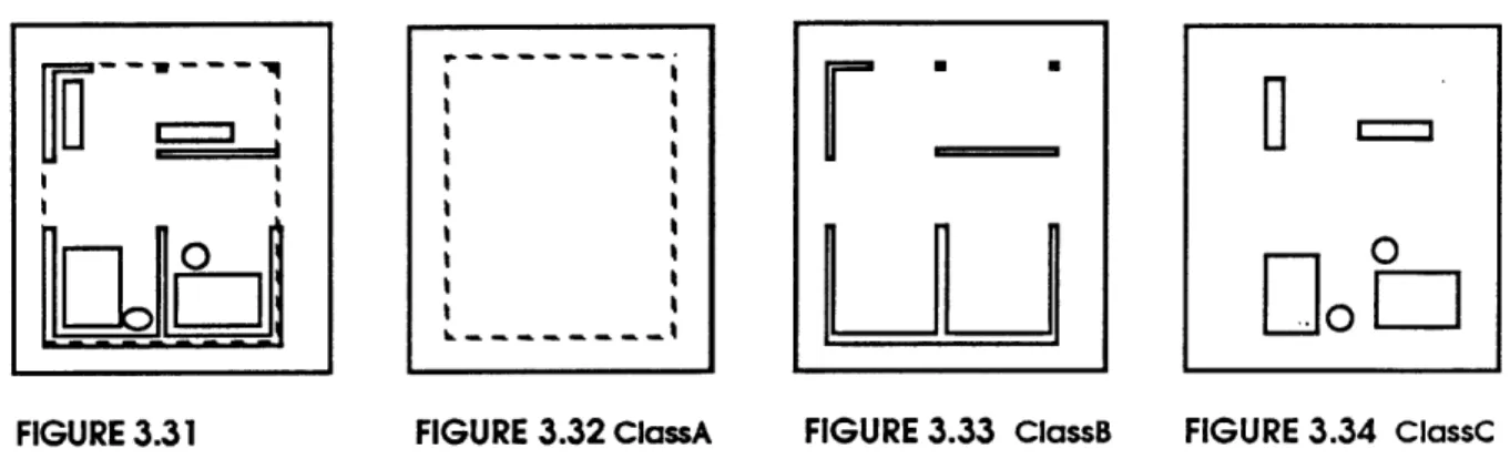
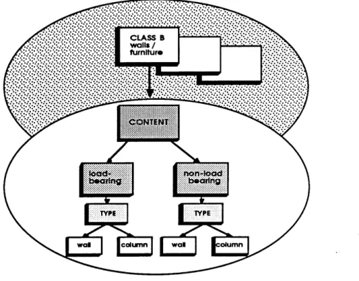
include extreme simplification. Simplification might destroy the content, thereby not enabling the designer to understand the image as a whole. The method is similar to laying trace paper over a photograph or drawing. Its importance can be understood by analyzing the plan of a small house (FIGURE 3.1), using the concepts of hierarchies and classes described in chapter 2.2. Within the image multiple classes can be identified. In this example we will assign the site a class, the walls and columns another class, and the furniture yet another. A class structure represents a configuration of objects and implies a hierarchy within the image of the detached house, or more appropriately, the typology single family detached house. This is further described in the tree structure in FIGURE 3.2. By expressing the diagram as shown we have stated that
walls and columns are dominant over furniture, and the class containing site is
dominant over all classes distinguished. Therefore, any intervention which occurs on the site affects all other elements and classes. In this example hierarchy is determined by dominance and control. Movement of objects on a higher level may affect lower levels. The purpose of this analysis is to help the designer understand the structure
inherent within classes of objects within a chosen image, or typology.
site
walls
columns
The hierarchy expressed above is easy to see in the simplistic image given containing a limited class structure. But, one can forsee the difficulties which might arise when
applying this holistic approach to a more complex image. In a simple image, the designer can begin to understand the correlation of objects as classes within a hierarchical system, by viewing the totality. The disadvantage to working through only this phase is that the complexity of an image can often distort and obstruct potential
themes, limiting the understanding and discovery by the designer. Therefore a second phase is introduced.
3.32 PHASE TWO
The second phase is more complex in nature. At this level we will continue to search for multiple themes through more explicit abstraction. Abstraction breaks down an image into its most essential elements and categories. In this instance, abstraction is used to find detail currently not obvious to the viewer. By the division of the complex image into
objects and groups of objects, discovery of multiple themes within various classes of
the image can more easily occur.
Habraken expresses this well in the following quote: "Our method of description must
allow us to scan the full complexity of the environment by moving down in to ever more detailed specification and up towards even larger abstractions." (Habraken 1984)
As objects are grouped they are also given a class. Each individual class is then
extracted from the primary image and an instance of it recreated in another location. At a later time we will composite the instances to again view the whole of the form, with a more comprehensive understanding of the nature of its composition. The intent is to
search for the relations and attributes of objects and classes, through form description.
Without breaking down the given image, these relations and attributes might be
overlooked.
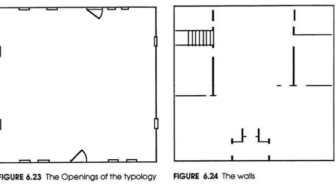
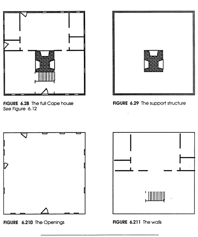
Once again using the previous image of the house, we subdivide the image into the
classes as in phase one. FIGURE 3.32 identifies ClassA, the site. FIGURE 3.33 identifies
ClassB, containing walls and columns, and FIGURE 3.34 ClassC of furniture. The names
given to each class in this example are arbitrary. To distinguish objects further, types
can be attached to objects within a class. In our definition, type is a simple description
of the form. For example, ClassB contains walls and columns which by their class
designation signifies their dominance over ClassC of furniture. Yet how do we distinguish
walls and columns from each other, and recognize one as controlling the other. We do
this by assigning a type to each object in addition to a class. Therefore, walls may be of
type wall, and columns may be of type column.
FIGURE 3.31 FIGURE 3.32 ClassA
F'
Ru
FIGURE 3.33 ClassBOO
U 3 0 FIGURE 3.34 ClassCEverything discussed in phase two is very straight forward. By using a simple example containing only three classes, everything could have occurred in the analysis of the
image as a whole. To take it further let us now analyze a new instance of a single class
of objects.
We will look at ClassB, containing walls and columns. Through analysis we wish to discover the system of organization, or theme, inherent within the class. At this level we could once again simplify the image by subdividing it into classes, repeating the steps previously mentioned. Presently we shall refrain. The image has been adequately
simplified.
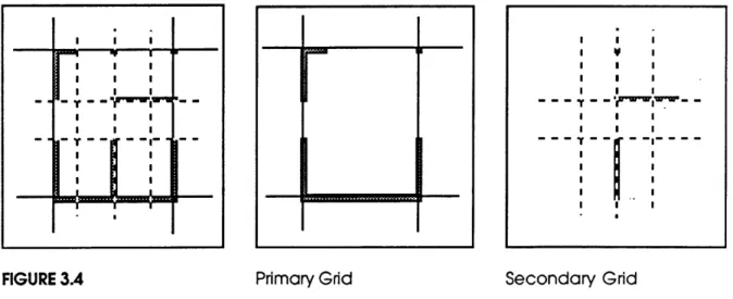
Using the ability of graphics over video, in an image processor, we begin to explore the
organizational system behind ClassB. By superimposing grid-lines on the walls and columns, we explore and analyze zones within the image. Though this analysis we discover a primary grid, which expresses the load-bearing points of the columns and walls, and a secondary grid expressing non-loadbearing elements (FIGURE 3.4). In finding this we would create a new class of objects containing non-loadbearing
FIGURE 3.4
Primary Grid
Secondary Grid
I I I
. . .. . . . .. .. .
- .. .. - - |- . - .
objects and one of load-bearing objects. Note that by descending into a class, we
have expressed that class as a configuration of elements, versus the previous phase
where elements in a given class did not form coherent configurations: they were
considered whole.
3.33 OBJECT DESCRIPTION
The discussion up to now has evolved around objects and their location in a
hierarchical system. The framework for classifying objects is built upon Habraken's
Hierarchies in Form. Through the analysis process, we disseminate an image to
determine its hierarchical framework. When the framework has been established, and
classes are assigned, a designer can begin to associate behavior to a class, or
objects within a class. "Objects" are entities, or variants, that are define, assigned a
class, and can be manipulated. "Behavior" implies that a class of objects can "know"
how it will perform under certain conditions.
Classes of objects contain static variables and state variables. Static variables contain
information such as an object's size, its color, and its location in the hierarchical
framework. State variables imply action, or behavior. For example, the nature of
hierarchy suggests that classes of objects of a lower-level can be controlled and
manipulated by those of a higher-level. In other words, a lower-level class is "bound" to
a higher-level class regarding specific actions. If I have a system of supports in -FIGURE
3.33 containing columns and walls, I recognize the supports as being of a higher-level in
the hierarchy than the roof. This is recognized because the action of moving the
column may cause the roof to collapse. Therefore, the column becomes a state
By assigning behavior to classes of objects the designer can begin to understand the ramifications that manipulating certain classes would have on other classes. This ability
to assign behavioral variables to classes of objects ventures into the realm of
object-oriented programming. Object-oriented programming will be further discussed in chapter four.
3.34 FOOTPRINTS
As a designer is exploring potential thematic systems, he may wish to save certain items: classes of objects, graphical annotation over the classes, or both. By creating a footprint, or a file, of the manipulated image, it can be recalled for viewing. A footprint
is an instance of chosen objects, or classes of objects, with all the knowledge of the objects retained. Its purpose is storing information that the designer may wish to view, or
composite, at a later time. A designer may explore and investigate numerous paths within a given image in search of the thematic system. He can choose a path, follow that path, record footprints of the adventures and potentials, and yet return to the mainstream if the chosen direction did not yield the anticipated introspection. By venturing down a less obvious road, one may find classes, or subclasses of objects
categorized that help explain the thematic system. The footprint acts as a record of
important benchmarks on such adventures with their own internal structure based upon the objects from which they were extracted.
A footprint can be a simple diagram, graphically representing a portion of a thematic system, or can be comprised of complex classes of objects with graphical annotation , emphasizing the structure explicitly. It includes elements a designer feels essential to the understanding and creation of a thematic system, highlighting and recording
The application of a footprint in the digital video environment can be threefold in nature. First, it acts as a recording device of stages along the design process, benchmarking important developments. Second, it creates an easy means for comparison of manipulated images against one another. Juxtaposition of the footprints may aid in
understanding the process of transformation, the essential actors, and classes involved. Third, it provides a simple means for testing these transformation, checking consistencies, understanding deviations from the intended path, therefore better
understanding the thematic system.
In the process of analysis a designer may discover themes at various levels of the hierarchy of forms. The themes may vary, yet they tie together to form a cohesive
whole. By juxtaposition of the primary themes, the composition or the whole becomes easier to visualize. Beyond juxtaposition we consider overlaying footprints over other footprints, creating a sandwich. This action is similar to overlaying layers of trace paper,
sketching, reevaluating the product, checking consistency, understanding relationships, testing themes, and exposing the hierarchy of classes of objects. With behavior attached to the various actors, or objects, consequences or certain actions can be more easily understood.
3.4 SUMMARY
Through this analysis, we have magnified a segment of an image in order to bring in more detail and, consequently, greater understanding of the nature of the form.
Classes are assigned to objects, and behavior attached to the classes. Intensification of meaning within a discovered theme can exist through injunction and juxtaposition of footprints. Understanding the behavior of classes of objects which are dominated by
other classes occurs through the assignment of attributes to the classes. Graphics over video allows the designer to annotate an image, creating a new image, emphasizing
discovered themes. Both graphics over video and attachment of behavior to classes of objects, help express contrast and comparison within an image, strengthening understanding of the intended meaning.
The ability to manipulate a digital image, and store the results for later reference, is
limited only by the imagination of the user. Viewing and exploring the transformation of simple elements into more complex forms in and of themselves is one potential.
Understanding the consequences of actions by assigning attributes to classes is
another. Juxtaposition of typologies, injunction, manipulation, distortion, subtraction,
Making variations on a theme is the crux of creativity.
But it is not some magical, mysterious process that
occurs when two indivisible concepts collide; it is a
consequence of the divisibility of concepts into already significant subconceptual elements.
Douglas Hofstadter
CHAPTER FOUR
Critical assessment and analysis of existing architypes creates the building block for understanding the intrinsic structure of a typology. Within this structure abstract relationships are translated into physical elements. Conventions which have evolved in
architecture over the centuries frame sociocultural expectations, regarding the selection and placement of architectural elements. These expectations reinforce historical examples and the selection and reinterpretation of their elements.
Through analysis, a designer can begin to understand essential elements and the rules of assemblage that constitute a physical representation: individual elements which,
when recombined by a the designer, might suggest a different theme, and create a new variation of a conventional typology.
4.1 ROLE OF THE OBJECT-ORIENTED GRAPHICS EDITOR
One often begins the design process through schematic sketches and diagrams. These sketches describe associations between various elements. "Bubble" diagrams,
matrices, and/or flow charts are implemented to understand relationships and their complexity. With the help of a graphics editor we begin the development of our own thematic system, building upon knowledge gained in the typological analysis. This
thematic system will soon become the bases for decision making and design reasoning.
The chosen model, discussed in chapter two section 2.2, is based on a simple notion of categories, hierarchies and classes. It is not the intent of this graphics editor to restrict design, but, to open up opportunities for recognizing relationships inherent in complex
associations.
With this tool, the process of designing, and the implications of designdecisions gain greater visibility This is two-fold in reason. First, assume that the designer
has defined the problem and knows her objectives. From this stand point she can
critique existing examples, problems and solutions through the analysis process described earlier. Most of this critical information should be gathered prior to entering the graphics editor, as if going to the library and gathering books and xeroxes that represent examples of how this problem, or a similar problem, has been solved in the past. This analysis of examples helps the designer frame the problem, develop objectives, and understand potential opportunities.
Second, we introduce the notion of an object-oriented graphics editor to describe a
design method, whereby objects are made aware of their attributes and behavior within the graphics environment. An object can know its size, color, position in the
load-bearing wall in a house I would be notified that it is a structural element and that I
can not move it without upsetting the physical structure of the design. The knowledge of such behavior and restrictions allows a system of rules and constraints to be
developed and assigned to classes of objects, governing their behavior.
4.2 CONCEPT OF AN OBJECT-ORIENTED GRAPHICS EDITOR
Exactly how a designer moves from subjective concepts to objective attainable requirements (abstract to concrete) in architectural design is somewhat of a mystery. The process of design is often ambiguous: "I like this", "I don't like that", "That is out of proportion", or whatever the aesthetic decision happens to be. Learning, or developing a method of design in terms of such abstract concepts is a difficult and time consuming task. In the following examples we shall adopt Habraken's method of design discussed in chapter two (Habraken 1982). The necessity for using a structured
approach will become evident as we proceed.
The object-oriented, in "object-oriented graphics editor", refers to designing with
structured objects, verses independent elements such as lines and vectors compounded to create objects. This method is closely akin to the way in which a designer transforms abstract concepts into physical realities; a physical reality of
elements and volumes. The notion of volumetric design, individual elements composed into a single object, is only one advantage of such an editor, yet it is tantamount to how we conceptualize the built environment.
These entities have little knowledge of themselves, and no knowledge of their behavior. The growing interest in structured objects is leading CADD into an era of the more natural design tool, and interface, by addressing objects as intelligent actors in the design
process. Have you ever designed a wall and thought of it as four lines?
4.3 BEHAVIOR IN AN OBJECT-ORIENTED ENVIRONMENT
The structure of an object-oriented system allows the user to assign attributes and
characteristics to various objects and classes (COX 1986). The variables and behavior of an object are inextricably bound within it. It becomes an intelligent actor that knows values of chosen variables and knows how to perform certain operations. For example, we may choose to layout walls, whereby some walls are load-bearing and others non-loadbearing. The wall is located at a given x and y coordinate, its color is
white and its size is z. Each of these (color, x, y and z) is a static variable attributed to the
wall...
The appearance of these variants is visually the same, but within the load-bearing object is a state variable which indicates that it is structural, and therefore can not be
moved without affecting other elements.... If someone attempts to move the wall, a flag could be noted that informs the designer of the implications of his actions. This action attaches behavioral information to objects, and aids in the management of the complexity of a design, by governing the activity that specific classes of objects can and can not perform.
* Structured Object refers to an object, or variant, that "knows" Its attributes and behavior
A static variable is a variable that is given a value when create but It may be changed: color,
size, linetype, etc.
''' A state variable is a variable that Is attached to an object, or class of objects and contains a behavior attributed to the given objects: movement of this may cause X to occur.
4.4 THE CREATION OF OBJECTS IN THE OBJECT-ORIENTED GRAPHICS EDITOR
Within the object-oriented graphics editor some geometric forms are predefined. The
designer will have rectangles, lines, points, etc. to work with. The nature of these objects, and their creation, differs from that of other graphics editors. When a predefined object is chosen, an instance of the predefined object is drawn. An instance refers to a copy of the original object. Attached to this instance is all of the knowledge of the original object, or parent. This propagation of knowledge is referred
to as inheritance, and is a distinct characteristic of object-oriented environments. An
object inherits the means to perform basic operations such as draw-self, resize-self,
moveto, etc ... In addition, each is given its own state. A sample psuedo-code of
Graphics Object named "Line" can be seen below:
(define Line
(an-instance-of Graphics-Object
(define :color) (define (draw-me) (move-me (x y)) ) ) )"Line" is an instance of Graphics-Object. Graphics-Object contains the basic attributes
and behavior for all graphics objects: lines, points, rectangles, etc.. A typical Graphics-Object might look something like this: