HAL Id: lirmm-02076914
https://hal-lirmm.ccsd.cnrs.fr/lirmm-02076914
Submitted on 22 Mar 2019
HAL is a multi-disciplinary open access
archive for the deposit and dissemination of
sci-entific research documents, whether they are
pub-lished or not. The documents may come from
teaching and research institutions in France or
abroad, or from public or private research centers.
L’archive ouverte pluridisciplinaire HAL, est
destinée au dépôt et à la diffusion de documents
scientifiques de niveau recherche, publiés ou non,
émanant des établissements d’enseignement et de
recherche français ou étrangers, des laboratoires
publics ou privés.
Characterization of bistable mechanisms for
microrobotics and mesorobotics
Mouna Ben Salem, Hussein Hussein, Guillaume Aiche, Yassine Haddab,
Philippe Lutz, Lennart Rubbert, Pierre Renaud
To cite this version:
Mouna Ben Salem, Hussein Hussein, Guillaume Aiche, Yassine Haddab, Philippe Lutz, et al..
Charac-terization of bistable mechanisms for microrobotics and mesorobotics: Comparison between
microfab-rication and additive manufacturing. Journal of Micro-Bio Robotics., Springer, 2019, 15 (1), pp.65-77.
�10.1007/s12213-019-00113-3�. �lirmm-02076914�
Characterization of bistable mechanisms for microrobotics and
mesorobotics
Comparison between microfabrication and additive manufacturing
Mouna Ben Salem · Hussein Hussein · Guillaume Aiche · Yassine Haddab · Philippe Lutz · Lennart Rubbert · Pierre Renaud
the date of receipt and acceptance should be inserted later
Abstract The use of mechanical bistable structures in the design of microrobots and mesorobots has many ad-vantages especially for flexible robotic structures. How-ever, depending on the used fabrication technology, the adequacy of theoretical and experimental mechanical behaviors can vary widely. In this paper, we present the manufacturing results of bistable structures made with two extensively used contemporary technologies: MEMS and FDM additive manufacturing. Key issues of these fabrication technologies are discussed in the con-text of microrobotics and mesorobotics applications.
Keywords mechanical bistable structures · curved beams · MEMS · FDM additive manufacturing · microrobotics · mesorobotics
This research is partially supported by the Investissements d’Avenir (Labex CAMI ANR-11-LABX-0004). The authors would like to thank Gilles Bourbon and Patrice Le Moal from FEMTO-ST Institute for their contributions to the simula-tion, the development of MEMS process and for microfabri-cation.
M. Ben Salem, H. Hussein, G. Aiche and Y. Haddab LIRMM, Universit´e de Montpellier, CNRS Montpellier, France
Tel: +33/0 467 41 85 85 Fax: +33/0 467 41 85 00 E-mail: [email protected] Ph. Lutz
FEMTO-ST Institute, Univ. Bourgogne Franche-Comt´e, CNRS, France
L. Rubbert, P. Renaud
ICube, INSA, Universit´e de Strasbourg, CNRS Strasbourg, France
1 Introduction
One of the major paradigms in the design of very small robots is the use of flexible structures. At small scales, mechanisms are hard to design and assemble, and are generally advantageously replaced by such structures [1]. Bistable structures are mechanical devices that have two stable states. They can be manufactured in con-junction with other parts of the microrobot in a mono-lithic manner. Using different micro-actuation princi-ples, it is possible to build complete microrobots on a unique substrate using bistable modules [2]. Bistable structures offer a number of other advantages. They can be fabricated at low cost and built using various manufacturing processes. They are usable for energy or information storage. No energy is required to main-tain a structure in one of its two stable states [2]. They are easily integrated into complex robotic architectures thanks to their planar shape and compactness [2]. They can be used in open-loop control without any sensor.
However, the use of bistable structures in the de-sign of microrobots and mesorobots requires consid-ering the modeling of their force-position characteris-tics and the limitations of the targeted manufacturing process. In the following, we consider more specifically two fabrication technologies: MEMS as it constitutes a technology that has been exploited for many micro-robots developed over the last decade. A representa-tive example of the use of bistable structures for the design of complete microrobots was presented in [2]. Each bistable structure is then used as an elementary module for the design of a high precision open loop con-trolled planar microrobots built using MEMS technol-ogy. The second technology is additive manufacturing. FDM (Fused Deposition Modeling) is of a particular interest for its wide availability, its potential low-cost
and more importantly the possibility to produce parts with high performance materials such as PEEK, com-patible for instance with the medical environment. This process indeed offers the possibility of manufacturing larger (mesoscale) structures if the application needs devices that can apply large forces or torques. Ion et al. propose meta structures based on bistable units [28]. In particular, microrobots for biomedical applications can be built thanks to the availability of biocompatible materials for FDM process. As an example of a medical application, a biomedical robot based on the bistable mechanism is developed in [29]. While MEMS are gen-erally made of silicon, a material with very good elastic behavior which retains the mechanical properties of the material, FDM is being used for production of polymer parts, which has different properties after manufactur-ing.
In this paper we present elements on the design and operation of bistable structures for microrobotics and miniaturized robots. Section 2 presents the basics of modeling of curved beams, the main components of bistable structures. Section 3 is dedicated to the fab-rication of curved beams using MEMS technology and section 4 presents a bistable mechanism manufactured by 3D printing and its experimental characterization. Manufacturing defects that arise from the miniaturiza-tion of parts which have dimensions close to the limits of the 3D printer are also being discussed as part of the manufacturing issues that comes with the use of this technology.
2 Modeling of curved beams
A curved beam structure is a component widely used in MEMS as a simple bistable mechanism that com-bines the advantages of passive holding and compliant mechanisms. Curved beams can be classified in three categories based on the fabrication process [3]:
– Precompressed curved beams, where the beam is fabricated rectilinear then it is compressed [3], [4], [5]. – Prestressed curved beams where during fabrication,
the beam is buckled due to residual stresses which are added by heating or oxidation [6], [7].
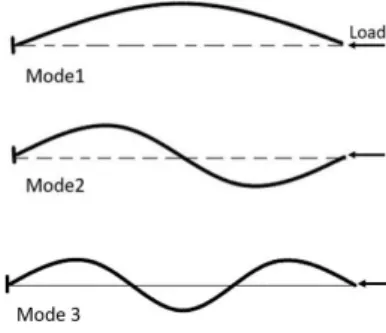
– Preshaped curved beams where the beam is directly fabricated at the first buckling shape mode(see Fig. 1) without residual stresses [8], [9], [10].
The mechanical behavior of the precompressed curved beam is symmetric between two sides of buckling. How-ever, the monolithic constraint and the difficulty to accurately set accurately the required buckling dimen-sions after fabrication make this solution difficult to use
Fig. 1 Representation of the three first buckling modes
in MEMS. The prestressed curved beam makes the in-tegration into a monolithic device easier, but the resid-ual stress is difficult to control by fabrication [3]. For the pre-shaped curved beam, despite the fact that sym-metry is lost and that bistability exists only under some conditions, fabrication and integration are simpler, specif-ically for MEMS applications. A solution used in the literature to improve the symmetry property of pre-shaped curved beams is to use hinged pre-pre-shaped curved beam structure [11], [9], [12]. The thickness of a por-tion of the beam is then kept very low as compared to the overall beam thickness. This portion is usually des-ignated as the elastic hinge. Local reinforcements are also proposed to be integrated with the pre-compressed length of a curved beam in [13] to adjust the post-buckling state and the snap-through properties. Few works can be found in literature that cover the model-ing and design of a preshaped curved beam. Based on Lagrangian approach, Vangbo et al. [14] carried out one of the first studies on precompressed curved beams that takes compressibility into account for small deforma-tions. Self-buckling behavior of microbeams in response to resistive heating was investigated by Chiao et al. [15]. Emam and Nayfeh examined in their studies [16], [17] the dynamics of precompressed curved beams. Cazottes [5] has investigated the bistability of a precompressed curved beam when actuated either by force or by moment. Elastic models for static and dynamic behaviors and experimental validation were presented by Camescasse in his thesis [4]. Chen et al. [18] showed the impor-tance of extensible elastic theory in the modeling of a curved beam. As for preshaped curved beams, Qiu et al. in [9] presented analytical modeling for the snap-ping force behavior due to an applied lateral force on the middle length of the beam. The analytical results were confirmed by FEM simulations and experiments on microfabricated prototypes. Hussein et al. consid-ered in [19] all the modes of buckling in the modeling
of snapping forces and internal stresses. In comparison with FEM simulations and experiments on microfab-ricated prototypes, the consideration of high modes of buckling results in more accurate modeling mainly for the stress calculation. This calculation is important in order to consider the stress limits in the dimension-ing of such a mechanism. Recently, the modeldimension-ing ex-pressions were further investigated in [30]. The effects of scaling the different dimensions and properties on the mechanical behavior of the curved beam were stud-ied and a design methodology was presented. In most cases, the action to switch the curved beam is a lat-eral force applied at the middle of the beam. Other-wise, the action can be also a force applied in different points [4], an electromagnetic field [8], an electrostatic field [20], [21] or moments applied in determined loca-tions on the beam [5], [22]. Park et al. [8] have presented analytical modeling of a preshaped curved beam when it is actuated by Laplace force distributed throughout the beam. The curved beam structure is being used in two mechanical forms: free or constrained, meaning that asymmetrical modes of buckling, such as mode 2 (pre-sented in Fig. 1) can occur or not. The free structure consists generally of a single curved beam, while the constrained structure consists of two or more curved beams that are connected in the middle by a shuttle which is the moving part as shown in Fig. 2.
Fig. 2 Transition between the two stable positions (1 and 3) of two curved beams connected in the middle to a shuttle. Mode 3 appears during transition (2).
An example of constrained structure is the bistable device shown in Fig. 3 [12]. Two stop blocks are placed between the two initial stable sides of the shuttle in three different states (as-fabricated, at position 1 and at position 2). In the as-fabricated state, no residual stress or deformation energy is present, therefore, the shuttle is only stable without holding forces. The stop blocks are physical stops used to add holding forces at the two stable positions and to define accurately the distance between them. These positions do not change unless an external force is applied in the switching direction that is higher than the holding force. Otherwise, the stable positions can change due to any kind of disturbance, such as thermal expansion.
Fig. 3 Bistable structure with hinged curved beams and U-shaped actuators for switching [12].
A preshaped curved beam has the following charac-teristics, also presented in Fig. 4: thickness t, depth b, span l, deflection d, beam shape w(x), initial height of buckling h, axial force P and the applied lateral force at the middle f .
Fig. 4 Clamped-clamped curved bistable beam at the initial position and after deflection.
The governing equation of the buckling and post-buckling of a curved beam is developed by Timoshenko in his famous book [23].
EId
4w
dx4 + P
d2w
dx2 = 0 (1)
where E is the Youngs modulus and I is the quadratic moment of the cross section. The solution of (1) is an infinite sum of buckling shape modes wjwhere the
con-stant modes aj are calculated in [9], [19] with a
varia-tional calculation after introducing the boundary con-ditions. w(x) = ∞ X j=1 ajwj(x) (2)
The axial force P is constant along the beam. In the as-fabricated position, P is equivalent to zero where no residual stress is present in the curved beam. Consider-ing the case of two curved beams attached to a shuttle in the middle as in Fig. 2, the asymmetrical buckling
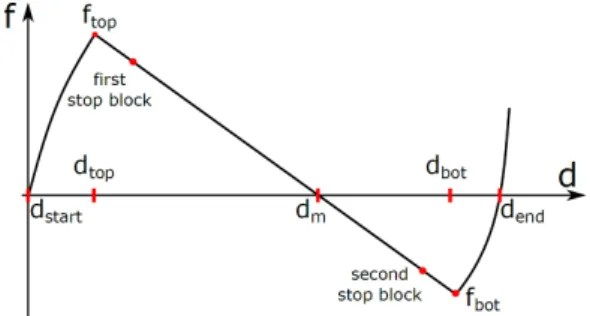
shape mode cannot occur during deflection. Switching the curved beam to the other side of buckling, it be-comes compressed and the axial force P increases as long as the beam deflection d gets closer to the mid-dle axis. At a certain limit, P reaches a defined value where bifurcation of solutions occurs in the variational calculation. At this point, the buckling shape mode 3 appears (see Fig. 1) in the shape of the curved beam and P becomes constant. After a certain limit of deflection in the other side of buckling, mode 3 disappears and the axial force P decreases. It is important to mention that P does not reach the limit of bifurcation unless Q = ht is higher than 2.31. In terms of the snapping forces, behavior of the curved beam during deflection is nonlinear at the borders while it becomes linear when mode 3 appears in the middle zone of deflection. Fig-ure 5 shows the snapping force curve with respect to deflection with highlights on remarkable points. As the mechanism is made by preshaped curved beams, it has an asymmetrical behavior.
Fig. 5 Force-Displacement curve of a preshaped curved beam.
While the two stable positions correspond to mini-mal energy configuration, one is energy free (as fabri-cated position) and the second one is non-zero energy. In practice, stop blocks that define the holding forces at each stable position and the distance between them are placed in the linear domain in the central part of that characteristic. The expression of the snapping force evolution in that domain is given by:
f = 64π2EIh l3 ( 4 3 − d h) (3)
The deflection zone where mode 3 appears is limited between dtopand dbot.
dtop, dbot= h( 28 27± 2π 3 r 1 6 + 16 81π2 − 1 Q2) (4)
The calculation details of the snapping force in the non-linear domain are presented in [19]. It is however im-portant to mention that the snapping force curve can be approximated to a straight line for high values of Q.
3 Microfabrication of curved beams
The compliant nature of the curved beam offers many advantages such as the absence of friction and back-lash, reduced wear, and low manufacturing costs. The use of silicon exhibits many additional advantages. The silicon has a nearly perfect elastic behavior with highly repeatable motion and without significant hysteresis or energy dissipation. It possesses in addition a long life-time with reduced fatigue. This material is widely ex-ploited in MEMS applications, its physical properties are well defined and the fabrication processes with sili-con are well developed. Figure 6 illustrates an example of the main steps in a fabrication process. The fabri-cation is realized on SOI (Silicon On Insulator) wafers which is a common case for MEMS devices.
Fig. 6 Fabrication process steps. SiO2hard mask etching on the backside (1), gold layer deposition (2), device and handle layers etched using DRIE process (3-4), structure releasing from the wafer using HF wet etching (5).
In the first step, the hard mask in the backside is lithographically patterned and etched using a pho-tomask. In the second step, a gold layer is sputtered, then patterned using wet etching through a photoresist layer which is patterned with a second photomask. This layer serves as a conductive line for supplying the elec-trical components (electro thermal actuators are used in this device). In the third step, the device layer is pat-terned lithographically through a third photomask and then etched using a deep reactive ion etching (DRIE) process. In the fourth step, the handle layer is etched by DRIE through the backside SiO2layer. Finally, the last
step consists in releasing devices from the wafer using HF wet etching. Useless parts fall into the HF solution during etching. Figure 7 shows an example of obtained device.
Fig. 7 A microfabricated bistable structure including ther-mal actuators and stop blocks.
Microfabrication details and characterization are given in [24]. The dimensions of the fabricated and charac-terised mechanism which is based on hinged preshaped curved beams (see Figure 8) are given in Table 1.
Table 1 Dimensions of the microfabricated bistable mecha-nism based on hinged preshaped curved beams
Parameter lhb thb bhb hhb
Value 500 mm 15 mm 100 µm 80 µm
Fig. 8 A hinged preshaped curved beam at the initial posi-tion, with tf = 20µm and lf = 6.8 mm
The behavior of the bistable mechanism shown in Fig. 7 and manufactured by microfabrication is charac-terized by experiments. Force-displacement characteris-tic is presented in Fig. 9. These measurements are made using an experimental setup adapted to the dimensions of the structures. The setup is composed of a force sen-sor (FemtoTools Microforce Sensing Probe) mounted on a robotic stage. When the latter is actuated, the force sensor triggers the bistable mechanism and re-turns the value of the force along with the associated displacement is recorded thanks to an interferometer (SIOS Metechnik GmbH) attached to the robotic stage. A dSPACE real time system is used to collect the data from the sensors (force and displacement) and sending control signals for the displacement of the robotic stage in real time. One can notice the good agreement be-tween experimental and theoretical results [31].
Fig. 9 Force-Displacement curves of a prototype composed of a hinged preshaped curved beams The blue curve is ob-tained by the analytical model and the red one is obob-tained by the experiments.
4 3D printing of curved beams 4.1 Towards 3D printed devices
Since the last decade, the use of additively manufac-tured (AM) devices have become more and more im-portant. As it goes adding material during the fabri-cation, it allows a new way of shaping the manufac-tured parts, unlike traditional machining. As it allows to prototype quickly, the trial and error method has be-come efficient, especially with polymer material, even though metal parts could also be manufactured using AM. However, as all manufacturing processes, the de-signer has to adapt his design to the additive manufac-turing constraints. Focusing on fused deposition model-ing (FDM) technology, a widespread AM technology, a filament material is deposited in plane layers. The final device consists of a stack of thin layers.
4.2 Main process parameters
A filament is made from extruded material, whose prop-erties can be characterized. However, once heated and fused in layers, properties can be significantly affected. In additive manufacturing, geometry, material and pro-cess parameters are tightly linked. As the structure of the part depends on how the material is added, the manufactured part characteristics such as mechanical properties (aesthetic, roughness could also be mentioned) depends on the process parameters. For many years, re-searches have been conducted to understand and pre-dict the behavior of the manufactured parts. Mohamed et al. [25] give a good overview of the different experi-ments presented in the literature, mainly for ABS ma-terial. Many parameters are analyzed, such as the layer thickness, the deposition orientation, the infill density and patterns, regarding their influence, mainly on me-chanical properties. To understand how it can influ-ence, the filament cross section is considered as a
ho-mogeneous surface, whose mechanical properties could be known, as nominal ones. Considering the angle be-tween the load and the cross section, it is possible to determine the mechanical properties. Since FDM allows changing many printing parameters, such as the previ-ously mentioned, it affects the stiffness considering the load direction and the orientation of the built structure. Moreover, the fusion between the filaments on the same layer, and between layers is only partial, meaning that some void is remaining, reducing the stiffness and then mechanical properties.
Fig. 10 Different infill patterns inducing different mechan-ical properties of the manufactured part: (left) concentric, (middle) triangle, (right) grid.
As a result, for instance, a linear pattern is stronger in the axis direction, but much weaker in the trans-verse direction, as delamination phenomena can appear, due to partial fusion between the deposited filaments. Changing pattern allows to improve part resistance in other directions (see Fig. 10). In short, the main en-gineering challenge is to find the best compromise be-tween all the fabrication possibilities in order to best suit the part requirements. An example is shown in Fig. 11. Researches have been conducted to optimize performance. For instance, automatic orientation opti-mization is presented in [26].
Fig. 11 Tensile characterization sample with different de-posed filament orientation.
4.3 3D printed bistable mechanism
From microscopic to mesoscopic, scale change could be a challenge especially while adapting the manufactur-ing technology to this change. When producmanufactur-ing small structures with 3D printing, several limits can appear. As the stack of fused filament makes the resistance of a part, small parts using few layers can actually ex-hibit weaknesses leading to ruptures (see Fig. 12). For instance, it was noticed that some software favors the creation of close contours, instead of making open lines, (Fig. 12. B and C). Furthermore, discretization of the filament width is important if precision is needed in small dimensions. If width is not a multiple of the fila-ment width (Fig. 12. D), lack or excess of material can be observed (Fig. 12. A).
Fig. 12 Slicing and toolpath generation. Lack of material due to printer resolution: (A) incomplete filling, (B) lack of filling, (C) partial filament fusing inducing weakness, (D) available contour width.
In a first step, these difficulties have been avoided by the choice of dimensions that are far from the limits of the fabrication machine (Fortus 400 MC, Stratasys) and have proportions close to those introduced in section 2 which allows keeping the same ratio Q. The bistable mechanism manufactured by 3D printing and used in the experiments has the following dimensions presented in Table 2 and shown in Fig 13:
Table 2 Dimensions of the 3D printed bistable mechanism
Parameter l t b h
Fig. 13 CAD presentation of the bistable mechanism used for experimentation.
The bistable behavior can be presented by the model given in section 2. The associated analytical model was also used to plot the force-displacement curve as shown in Fig. 16. In order to characterize the bistable mecha-nism, a dedicated setup has been built. It is made up of a laser-based displacement sensor (Keyence LK-H152) that has a measuring range of ± 40mm with a res-olution of 0.25 µm, a force sensor (Sauter FK50) that can apply a maximum force of 50N with an accuracy of 0.02N and a mounting bracket to fix the bistable mech-anism and ensure the boundary conditions (see Fig. 14). An additional damping is added to prevent the move-ment of the mechanism during the experimove-ment, since it was manufactured with an open frame. A force is ap-plied using a linear displacement device to the double curved bistable beam and the corresponding displace-ment is measured using the laser sensor.
Fig. 14 Dedicated experimental setup, built for force dis-placement measurement.
During the experiments, the bistable mechanism passes as expected by the third mode of buckling, but when arriving at the equilibrium position the mechanism goes through an unexpected configuration (see Fig. 15. B). This shape is probably due to the fact that the stack of deposit filament does not create a fully solid part.
Fig. 15 Different positions of the bistable beam: (A) Sta-ble position as fabricated, (B) Equilibrium position and (C) Second stable position.
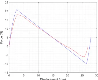
The result of the experimental characterization is given in Fig. 16. The figure shows a comparison between the force-displacement curve obtained by the analyti-cal model and the one obtained by the experiments. A remarkable difference in the amplitude of the force is noticed, however the displacements are in good agree-ment.
Fig. 16 Comparison of the force-displacement curves ob-tained by analytical model in blue and the experiments in red.
The dimensions of the manufactured structure are verified after 3D printing, therefore the Young’s mod-ulus (post-manufacturing) may be the origin of this difference considering that the expression of the force given in section 2 is directly proportional to the Young’s modulus E. Therefore, the post-manufacturing Young’s modulus is characterized in order to integrate it to the results of the analytical model.
To determine the influence of the additive manufac-turing on the Young’s modulus value, an experiment is performed on test beams manufactured in the same
way as the bistable mechanism and using the same ex-perimental setup (See Fig. 17).
Fig. 17 Experimental setup used for the evaluation of the Young’s modulus after manufacturing.
The measurements of forces and displacements made on the test beam allow the evaluation of the experi-mental Young’s modulus using the following displace-ment expression of an end-loaded cantilever presented in Fig. 18.
v = P L
3
3EI (5)
where E is the Young’s modulus, I is the quadratic moment of the cross section P is the force applied at the tip of the cantilever, L is the length of cantilever and v is tip deflection.
Fig. 18 Representation of an end-loaded cantilever.
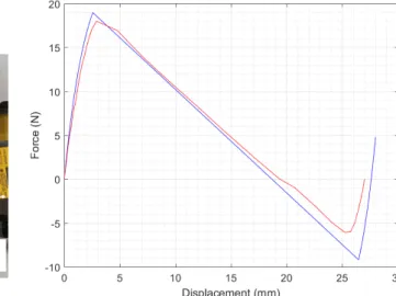
The average value of the experimental Young’s mod-ulus is equal to 1772 MPa compared to a theorical Young’s modulus equal to 1944 MPa. By integrating this Young’s modulus in the analytical model of the bistable mechanism, we obtain the results shown in Fig. 19. The error between the analytical and experi-mental amplitude decreases and the force-displacement curves show a better agreement between the presented theory in section 2 and the experiments.
Fig. 19 Comparaison of the force-displacement curves ob-tained by analytical model with updated Young’s modulus in blue and the experiments in red.
4.4 Miniaturization of a 3D printed bistable mechanism
In a second step, the fabricated structures are minia-turized. They have the dimensions given in Table 3.
Table 3 Dimensions of the 3D printed miniaturized bistable mechanism
Parameter l t b h
Value 18 mm 0.35 mm 2 mm 2.4 mm
In this case, the manufacturing problems described previously and shown in Fig. 12 appear. The same 3D printer is used. The beam width consists of a single fused filament (Fig. 12. C), meaning that infill pattern cannot be changed. The second stable position of the bistable mechanism shows that deformation is different from theory (Fig. 20, right). Actually, some lack of ma-terial and plasticity induce unexpected behavior. Fig-ure 12. B is taken from the tested structFig-ure in Fig. 20. It shows an example of a lack of material in the 3D printing process that we tried to improve as shown in the zoomed picture of the miniaturized bistable mech-anism in Fig. 22.
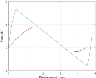
The first experimental characterizations have shown that results are significantly different (Fig. 21). The fig-ure shows a significant error, mainly about extremum force values and the evolution of the force-displacement curve obtained in the experiment.
Fig. 20 Bistable curved beam (left) as shaped stable posi-tion, (right) other stable position limited by stop blocks.
Fig. 21 Comparaison of the force-displacement curves ob-tained by analytical model in blue and the experiments in red of a miniaturized bistable mechanism
These results show that the greatest care must be taken when designing mesoscopic structures with FDM technology. The orientation and setting of the filament deposit can result in excess or lack of material (shown in Fig. 12) in the final part which can influence the be-havior of the bistable mechanism (as shown in Fig. 15 and Fig. 20). Additionally, 3D printing changes the Young’s modulus of the deposited filament which must be taken into consideration while characterizing the bistable mechanism.
Fig. 22 A zoomed (x50) picture of the middle junction of the miniaturized bistable mechanism
5 Discussion and conclusion
In this paper, we presented the key concepts for the de-sign and manufacture of bistable structures for micro-robotic and mesomicro-robotic applications. Two major man-ufacturing technologies were considered. The first one is microfabrication which allows the manufacturing of parts whith behaviors similar to modeling due to the elastic characteristics of the materials that are being used. However it remains an expensive fabrication pro-cess even for mass production. The second one is FDM 3D manufacturing which opens up a variety of possi-bilities for low cost devices that can be larger in size. However, the principle of additive manufacturing based on fused filament makes the mechanical behavior of the fabricated device difficult to predict and highly depen-dent on the trajectory control algorithms used in 3D printers. The results presented in section 4 show a dif-ference in the force-displacement behavior of the 3D printed structure mainly due to the different Young’s modulus after manufacturing which has been proven with characterization experiments. As for the minia-turized 3D printed bistable mechanism, other manu-facturing defects appear which make the experimental behavior further away from the analytical result. These issues can be improved either by a better control of fabrication parameters. To summarize, different points of comparison between these two manufacturing meth-ods are highlighted in the table. Future work will aim to define design rules for a better match between the theoretical and experimental models, considering the constraints of FDM, the printed specifications and its influence on the properties of the material. As another perspective for this work, a comparison study between FDM and other additive manufacturing process such as the Polyjet (developed by Stratasys).
Microfabrication 3D prin ting Material Silicon: a material with v ery go o d elastic b eha vior, it fa-cilitates the m a n ufacturing of bistable mec hanism P olymer suc h as ABS and P olycarb onate, it has more com-plex m ec hanical pr op erties M o reo v er, the Y oung’s mo dulus ch anges significan tly after man ufacturing and therefore it is necessary to measur e it Structure Homogeneous structure whic h results in a b etter estima-tion of the mec hanical prop erties b efore fabrication Non homogeneous structure formed of slices and la y ers. The m ec hanical pro p erties dep end widely on the fabrica-tion pro cess Structural Di-mensions W ell adapted for v ery small structures (from a n order of a few millimeters up to 1 or 2 cm) W el l adapted for larger structures (starting from a few cen timeters) Geometry Microfabrication is constrained generally b y monolithic structures and requires the use of flexible comp onen ts Complex 3D geometrical structures could b e designed and fabricated Assem bly Complexit y for the assem bly with other comp onen ts Easy assem bly due to the larger scale Man ufacturing cost High cost b ecause it requires the access to a clean ro om. Ho w ev er, the cost can b e considerably reduced if a batc h pro cess is carried out Lo w er cost whic h mak es it easier and faster to prin t a nd test differen t mec hanisms Applicable forces Applicable fo rce s range from a few mN to a h undred mN Applicable forces range from appro ximately 1 N and go up to more than 20 N Displacemen ts b et w e en the tw o stable states The displacemen ts b et w een the tw o stable p ositions are v ery lo w, from a few micrometers up to a h undred mi-crometers The displacemen ts b et w een the tw o stable p ositions a re quite large, from a few mm up to tens of mm
References
1. M. Grossard, N. Chaillet, and S. Rgnier, Flexible robotics: applications to multiscale manipulations, John Wiley & Sons, (2013)
2. V. Chalvet, Y. Haddab and P. Lutz, A microfabricated planar digital microrobot for precise positioning based on bistable modules, IEEE - Transactions on Robotics, vol.29, Issue 3, pp. 641-649 (2013)
3. S. S. H. Zaidi, Z. Cherfi-Boulanger, and F. Lamarque, Con-tactless energy transfer and control strategy for bistable micro-actuator, Ph.D Thesis, University of Technology of Compigne, (2011)
4. B. Camescasse, Actionnements statique et dynamique dun mecanisme bistable : aspects modlisation, conception et ex-primental, Ph.D. Thesis, Pierre and Marie University Curie, (2013)
5. P. Cazottes, Actionnement des systemes bistables: mod´elisation et ´etudes exp´erimentales, Ph.D Thesis, Pierre and Marie University Curie, (2009)
6. I. Z. Pane and T. Asano, Investigation on bistability and fabrication of bistable prestressed curved beam, Japanese Journal of Applied Physics, vol. 47, pp. 52-91, (2008) 7. B. Charlot, W. Sun, K. Yamashita, H. Fujita, and
H. Toshiyoshi, In-plane bistable nanowire for mem-ory devices, Design, Test, Integration and Packaging of MEMS/MOEMS, Symposium on. IEEE, pp. 254-258, (2008)
8. S. Park and D. Hah, Pre-shaped buckled-beam actuators: theory and experiments, Sensors and Actuators A: Physical, vol. 148, no. 1, pp. 186-192, (2008)
9. J. Qiu, J. Lang, and A. Slocum, A curved-beam bistable mechanism, vol. 13, no. 2, p. 137-146, (2004)
10. B.T. Liao, H.H. Shen, H.H. Liao, and Y.J. Yang, A bi-stable 2x2 optical switch monolithically integrated with variable optical attenuators, Optics express, vol. 17, no. 22, pp. 19919-19925, (2009)
11. B. D. Jensen, M. B. Parkinson, K. Kurabayashi, L. L. Howell, and M. S. Baker, Design optimization of a fully-compliant bistable micromechanism, ASME Interna-tional Mechanical Engineering Congress and Exposition, vol. 48109, p. 21-25, (2001)
12. H. Hussein, V. Chalvet, P. Le Moal, G. Bourbon, Y. Haddab, and P. Lutz, Design optimization of bistable mod-ules electrothermally actuated for digital microrobotics, IEEE/ASME International Conference on Advanced Intel-ligent Mechatronics AIM, pp. 1273-1278 (2014)
13. R. Gao, M. Li, Q. Wang, J. Zhao, and S. Liu, A novel design method of bistable structures with required snap-through properties, Sensors and Actuators A: Physical, vol. 272, pp. 295-300 (2018)
14. M. Vangbo, An analytical analysis of a compressed bistable buckled beam, Sensors and Actuators A: Physical, vol. 69, no. 3, pp. 212-216, (1998)
15. M. Chiao and L. Lin, Self-buckling of micromachined beams under resistive heating, Journal of Microelectrome-chanical Systems, vol. 9, no 1, pp. 146-151 (2000)
16. S. A. Emam and A. H. Nayfeh, On the nonlinear dynam-ics of a buckled beam subjected to a primary-resonance ex-citation, Nonlinear Dynamics, vol. 35, no 1, pp. 1-17 (2004) 17. A. H. Nayfeh and S. A. Emam, Exact solution and sta-bility of postbuckling configurations of beams, Nonlinear Dynamics, vol. 54, no 4, pp. 395-408 (2008)
18. J.S. Chen and H.W. Tsao, Static snapping load of a hinged extensible elastica, Applied Mathematical Mod-elling, vol. 37, no 18-19, pp. 8401-8408 (2013)
19. H. Hussein, P. Le Moal, G. Bourbon, Y. Haddab, and P. Lutz, Modeling and stress analysis of a pre-shaped curved beam: influence of high modes of buckling, International Journal of Applied Mechanics, vol. 7, no. 4, p. 1550055, (2015)
20. S. Krylov and N. Dick, Dynamic stability of electrostat-ically actuated initially curved shallow micro beams, Con-tinuum Mechanics and Thermodynamics, vol. 22, no. 6-8, pp. 445-468, (2010)
21. F. Tajaddodianfar, M. H. Yazdi, and H. N. Pishkenari, Dynamics of bistable initially curved shallow microbeams: Effects of the electrostatic fringing fields, IEEE/ASME In-ternational Conference on Advanced Intelligent Mechatron-ics AIM, pp. 1279-1283 (2014)
22. B. L. Stoimenov, J. M. Rossiter, and T. Mukai, Manufac-turing of ionic polymer-metal composites (IPMCs) that can actuate into complex curves, Electroactive Polymer Actua-tors and Devices (EAPAD), International Society for Optics and Photonics, vol. 6524. (2007)
23. S. Timoshenko, Theory of elastic stability, McGraw-Hill, (1961)
24. Q. Chen, Y. Haddab, and P. Lutz, Microfabricated bistable module for digital microrobotics, Journal of Micro-Nano Mechatronics, vol. 6, pp. 1-12, (2010)
25. O. A. Mohamed, S. H. Masood, and J. L. Bhowmik, Opti-mization of fused deposition modeling process parameters: a review of current research and future prospects, Advances in Manufacturing, vol. 3, no 1, pp. 42-53 (2015)
26. E. Ulu, E. Korkmaz, K. Yay, O. B. Ozdoganlar, and L. B. Kara, Enhancing the Structural Performance of Addi-tively Manufactured Objects Through Build Orientation Optimization, Journal of Mechanical Design, vol. 137, no 11, pp. 111410 (2015)
27. T. Letcher, B. Rankouhi, and Sina Javadpour, Experi-mental study of mechanical properties of additively man-ufactured ABS plastic as a function of layer parameters, International Mechanical Engineering Congress and Ex-position, American Society of Mechanical Engineers, pp. V02AT02A018-V02AT02A018 (2015)
28. A. Ion, L. Wall, R. Kovacs, and P. Baudisch, Digital Me-chanical Metamaterials, The 2017 CHI Conference on Hu-man Factors in Computing Systems, pp. 977-988 (2017) 29. M. Ben Salem, G.Aiche, L. Rubbert, P. Renaud and Y.
Haddab, Design of a Microbiota Sampling Capsule using 3D-printed Bistable, 40th IEEE. International Engineering in Medicine and Biology Conference, pp. 4868-4871 (2018) 30. H. Hussein, P. Le Moal, R. Younis, G. Bourbon, Y. Haddab, and P. Lutz, On the design of a preshaped curved beam bistable mechanism, Mechanism and Machine The-ory, vol. 131, pp. 204-217 (2019)
31. H. Hussein. Contribution to Digital Microrobotics: Mod-eling, Design and Fabrication of Curved Beams, U-shaped Actuators and Multistable Microrobots, PhD thesis, Bour-gogne Franche-Comt´e University, (2015)