HAL Id: hal-02281356
https://hal.archives-ouvertes.fr/hal-02281356
Submitted on 1 Oct 2020
HAL is a multi-disciplinary open access
archive for the deposit and dissemination of
sci-entific research documents, whether they are
pub-lished or not. The documents may come from
teaching and research institutions in France or
abroad, or from public or private research centers.
L’archive ouverte pluridisciplinaire HAL, est
destinée au dépôt et à la diffusion de documents
scientifiques de niveau recherche, publiés ou non,
émanant des établissements d’enseignement et de
recherche français ou étrangers, des laboratoires
publics ou privés.
Faradaic and/or capacitive: Which contribution for
electrochromism in NiO thin films cycled in various
electrolytes?
Mathias da Rocha, Bruce Dunn, Aline Rougier
To cite this version:
Mathias da Rocha, Bruce Dunn, Aline Rougier. Faradaic and/or capacitive: Which contribution for
electrochromism in NiO thin films cycled in various electrolytes?. Solar Energy Materials and Solar
Cells, Elsevier, 2019, 201, 110114 (8 p.). �10.1016/j.solmat.2019.110114�. �hal-02281356�
Faradaic and/or capacitive: Which contribution for electrochromism in NiO
thin
films cycled in various electrolytes?
Mathias Da Rocha
a, Bruce Dunn
b, Aline Rougier
a,* aCNRS, Univ. Bordeaux, Bordeaux INP, ICMCB, UMR 5026, F-33600, Pessac, FrancebDepartment of Materials Science and Engineering, University of California, Los Angeles, CA, 90095, USA
Keywords: Electrochromism Nickel oxide Mechanism Capacitive Device A B S T R A C T
This study compares the electrochromic performance of NiO thinfilms deposited by RF magnetron sputtering cycled in lithium, sodium and small cations free based electrolytes, namely 1:9 LiTFSI in EMITFSI, 1:9 NaTFSI in EMITFSI and EMITFSI respectively. Regardless of the electrolyte nature, NiO thinfilms show similar electro-chromic properties associated with an optical switch from colorless to brownish upon oxidation correlated to a modulation of transmittance close to 40 % associated with a good electrochemical stability. Interestingly, de-pending on the electrolyte nature, the EC behavior is correlated with various CV shapes raising the question of the mechanism involved. In particular, the reversible coloration mechanism cannot be only described by a single insertion/extraction of lithium ions, as observed for tungsten oxide in lithium media. The rectangular shape of the CV curves of NiO thinfilms in neat electrolyte and the behavior of NiO with various scan rates suggest that the EC properties result from a combination of both faradaic and capacitive contributions, with redox reactions largely occurring at the surface. Integration of NiO thinfilms in a full device is illustrated in double sided PANI/ white electrolyte-EMITFSI/NiO EC devices showing simultaneous progressive color changes from blue to green and white to brown, on PANI and NiO sides, respectively.
1. Introduction
Modern architecture for both houses and buildings makes extensive use of fully glazed exteriors, thus providing numerous opportunities for smart windows. Smart windows offer indoor temperature regulation which increases the comfort of the occupant [1,2]. Among the various smart window approaches, electrochromic windows have received considerable attention, however, their widespread commercialization still suffers from critical issues including cycle life, pin holes in large panels, and cost [3]. This smart window technology uses electro chromic materials that display a reversible change in optical properties under an applied voltage. The operating principle is based on the re versible exchange of ions (via the electrolyte) and electrons between the two electrodes (via the external circuit); this resembles the electro chemical processes occurring in ion insertion batteries, such as lithium ion batteries. Currently, the majority of smart windows are designed to combine WO3, the most commonly used inorganic electrochromic ma
terial, with either IrO2leading to blue coloration or to NiO. NiO has the
advantage of being less expensive than IrO2and, when combined with
the cathodically colored blue of WO3, brings a neutral color (gray)
which is often more suitable for commercial applications. However, the
mechanism of NiO coloration, especially in lithiated electrolytes, has not been well established. The initially proposed mechanism based on Li ion insertion/desinsertion has been questioned as recent investiga tions have shown that Li free electrolytes also produced coloration [4].
Passerini and co workersfirst reported the coloration mechanism in NiO as arising from the insertion/desinsertion of lithium ions. NiO as an anodic electrochromic material, switches from a bleached reduced state to a colored oxidized one. The EC mechanism was often expressed [5 9] by the following equations
Ni1 xO + yLi++ye−↔ LiyNi1 x yO (1)
or
LiyNiOx+ zLi++ze−↔ Liy+zNiOx (2)
More recently, Moulki et al. [10], reported the successful coloration of nickel oxide thinfilms through oxidation without pre insertion of lithium ions. This process suggests that anions, namely TFSI−in that case, were involved in the coloration process. Further cycling showed a reversible bleaching/coloration process suggesting that both anions and cations participated in the mechanism. Wen et al. also indicated that both cations and anions contributed to the charge exchange, favoring
*Corresponding author.
surface reactions rather than bulk processes [11].
In this study we consider the different electrochromic responses of NiO using ionic liquid electrolytes which either contain lithium salts, sodium salts or are salt free. The coloration properties are determined using cyclic voltammetry at various scan rates in combination with transmittance modulation, which enables us to obtain greater insight regarding differences in electrochemical kinetics. Opening the range of suitable electrolytes in which NiO thin films exhibit good EC perfor mance allows to consider NiO thin films in devices exhibiting new configurations aiming at applications ranging from smart windows to displays. Indeed, the combination of EC materials is no more limited to insertion compounds such as WO3but materials of which EC properties
are reported in salt free electrolytes become good candidates. Conductive polymers belong to those categories of materials switching their optical properties in salt free electrolytes. For instance, we earlier reported PEDOT NiO devices showing good compatibility in this type of electrolyte for both electrodes [4]. More recently, our group has fo cused on suggesting non common devices configuration leading to hy dride device combining oxide and polymers [12] or to devices of which properties lie on the modulation of colors [13]. Further step was raised by adding a white electrolyte membrane in between two EC layers leading to devices showing a simultaneous color change on both sides of the device. Herein, further investigation of hybrid device is carried out through the integration of NiO combined with a conductive polymer, namely polyaniline, separated by a white membrane electro lyte.
2. Experimental details
2.1. Deposition of NiO thinfilms by RF magnetron sputtering NiO thin films were deposited on 2.5 × 2.5 cm2 In
2O3:Sn coated
glasses (SOLEM ITO glass, ~25Ω/□) by reactive RF magnetron sput tering from 75 mm diameter nickel (99.99 %) targets (Neyco). During the deposition process, the distance from the substrate to the target was fixed at 8 cm. Such conditions led to the production of uniform thin films. The gas flow ratio of Ar (99.99 %) to O2(99.99 %) wasfixed by
massflow controllers at 98:2 (sccm), and a working pressure of 4 Pa. The power was maintained at 90 W. The thickness of the films was found to be about 330 nm, as measured by a profilometer (Dektak), leading to a deposition rate of 17 18 nm/min.
2.2. Characterization methods
Thefilm structure was determined by X ray diffraction (XRD) using a PANanalytical X'pert MPD diffractometer with Cu Kα incident ra diation. The morphology of the films was characterized by Scanning Electron Microscopy (SEM) (Hitachi Tabletop microscope TM 100). Cyclic voltammograms (CV) and chrono amperograms (CA) were ob tained using a three electrode glass cell consisting of Glass/ITO/NiO as the working electrode, a Pt sheet as counter electrode and a Saturated Calomel Electrode SCE (0.234 V/ENH) reference electrode. The ionic liquid electrolytes (Solvionic; purity > 99.99%) consisted of 1:9 mol ratio of lithium or sodium bis(trifluoromethanesulfonyl)imide (LiTFSI, NaTFSI) dissolved in 1 ethyl 3 methylimidazolium bis(tri fluoromethanesulfonyl)imide (EMITFSI). Neat EMITFSI electrolytes were also investigated. The CV and CA measurements were made using a Biologic potentiostat. In situ optical transmittance measurements of the Glass/ITO/NiO electrode at a wavelength of 550 nm were carried out using a Varian Cary UV Visible NIR Spectrophotometer.
3. Results and discussion 3.1. Structural characterization
The XRD pattern of the NiO (Fig. 1a) consists of a major peak
located at 2Ɵ = 37.28°. The NiO thin film crystallizes in the cubic rocksalt structure (Fm 3m) with a strong (111) preferred orientation. The lattice parameter of 4.177 Å is close to that of bulk NiO (4.164 Å) (JCPDS 00 001 1239). A crystallite size of about 30 35 nm is calcu lated using the Scherrer formula. SEM micrographs indicate a homo geneousfilm with significant porosity (Fig. 1b). A TEM image (Fig. 1c) indicates a columnar growth morphology as expected from deposition conditions combining a high pressure in the sputtered plasma and room temperature substrate [14].
3.2. Electrochromic behavior
3.2.1. Comparison of electrolyte nature
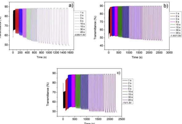
Fig. 2a, b, c show a series of CVs at a 40 mV/s scan rate for NiO thin films cycled in 1:9 LiTFSI EMITFSI, 1:9 NaTFSI EMITFSI and EMITFSI. While the electrochromic behavior is reversible, in order to fully bleach or color NiO, a small adjustment of the voltage window was required. The evolution of the in situ transmittance recorded at specific voltages maintained for various durations from 1 s to 45 s is displayed inFig. 3a and b, c. Regardless of the electrolyte, a reversible process is observed where there is a decrease in transmittance upon oxidation and an in crease in transmittance upon reduction whatever the time. An activa tion occurs in the veryfirst cycles leading to an increase in capacity. In lithium and sodium based electrolytes, some similarities in the CV curves are observed as there are two distinct peaks in both the anodic and cathodic sweeps. The separation between these peaks is further apart in the Na based electrolyte requiring the oxidation potential to be increased from 1.2 to 1.4 V in order to reach similar transmittance modulation. With the neat EMITFSI electrolyte, NiO exhibits a rectan gular CV shape between−0.5 V and 1.3 V. This shape generally arises from capacitive behavior. For all of the electrolytes, NiO films re versibly switch from a colorless to a brownish state which is correlated with modulation of the transmittance. Interestingly, for a duration time of 45 s, whatever the electrolyte, the transmittance decreases from 88 % down to about 48 % corresponding to a contrast of 40 %. The main differences in the transmittance evolution occur for very short dura tions mostly in the bleached state with a transmittance that reaches only 70 % for 1 s in salt free electrolyte, and required 5 s for a stable value of about 88 %. In Li, or Na based electrolytes, the transmittance in the bleached states is close to the maximum value as earlier as 2s.
The transmittance as a function of time identifies a memory effect, which is described as the ability to remain in the colored oxidized state when no potential is applied. This behavior was characterized using a 4 phase protocol (Fig. 4andTable 1). In, phase 1, a negative voltage is applied for a few seconds until reaching the full reduction state (i.e. maximum in transmittance). Then, in phase 2, no voltage is applied for few minutes. The phases 3 and 4 are similar to 1 and 2 but now involve
Fig. 1. a) X-Ray diffraction pattern of 250 nm NiO thin films deposited on glass substrate, b) SEM morphology, c) TEM morphology.
the oxidation state (i.e. minimum in transmittance). In these experi ments, the voltages used to bleach or color are the extreme values used in the CVs for each electrolyte, namely−1.2 1.2 V for Li; −1.0 1.4 V for Na; and −1 V 1.3 V for EMITFSI. To a first approximation, NiO behavior seems comparable for all three electrolytes. After phase 1 (i.e. reduced state), the transmittance sharply decreases by 2 3 % prior to stabilizing after 5 10 min during phase 2. In contrast, after the oxida tion state (phase 3), the transmittance continuously increases and does not stabilize even after 30 min.
Table 1lists the characteristic features of the memory effect and the
switching times for NiO cycled in the three different electrolytes. The former corresponds to the modulation in transmittance after 1000 s in the bleached state and 1500 s in the colored state while the switching time corresponds to the time required for reaching 90 % of full trans mittance. In all electrolytes, NiO tends to bleach more easily in open circuit. The faster bleaching time than the coloration one was already reported [15] and attributed to the transition from a conductive colored state composed of Ni3+ and Ni2+ to a less conductive one in the
Fig. 2. Voltammetry cyclic of (a) NiO/1:9 LiTFSI-EMITFSI/Pt vs SCE using a 40 mV scan rate and 1.2V–1.2V voltage window, (b) NiO/1:9 NaTFSI-EMITFSI/Pt vs SCE using a 40 mV scan rate and -1V–1.4V voltage window, (c) NiO/EMITFSI/Pt vs SCE using a 40 mV scan rate and -1V–1.3V voltage window.
Fig. 3. in-situ transmittance vs time of chronoamperometry at the wavelength of 550 nm of (a) NiO/1:9 LiTFSI-EMITFSI/Pt, (b) NiO/1:9 NaTFSI-EMITFSI/Pt, (c) NiO/ EMITFSI/Pt. The voltage range for chronoamperometry has been chosen on the basis of CV at 100 mV/s.
bleached state NiO (Ni2+). Although sodium ions are larger than li thium ions, the switching time for the NaTFSI EMITFSI electrolyte is shorter than the one for the LiTFSI EMITFSI electrolyte. In general, the electrochromic properties of NiO are almost the same for all three electrolytes, including the neat EMITFSI electrolyte.
3.2.2. Comparison of WO3and NiO in lithium based electrolyte
The faculty of NiO thinfilms to cycle in salt free electrolytes raises the question of the mechanism. Commonly, EC properties in oxides are associated with insertion desinsertion phenomenon while cycling in protonic, lithium or sodium based electrolytes. To provide greater in sight of the EC behavior for NiO, its EC properties were compared to those of the state of the art EC oxide, namely WO3, a material for which
the insertion mechanism in lithium and sodium based electrolytes is well established.
In lithium based electrolytes [14 18], WO3undergoes the following
reaction:
WO3+ xLi++ xe−↔LixWO3 (3)
Upon reduction, cathodically colored WO3switches from a colorless
to a blue state. NiO and WO3 thin films were cycled in 1:9 LiTFSI
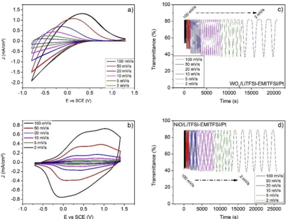
EMITFSI at various scan rates and the in situ transmittance was re corded. During all measurements, the voltage windows were kept constant, between−0.8 and 1.3 V for WO3(Fig. 5a) and−0.7 and
1.4 V for NiO (Fig. 5b). As the scan rate increases from 2 to 100 mV/s, the current density for both NiO and WO3increases. However, the re
spective bleaching behavior is different for the two materials. The voltage needed to fully bleach WO3increases from 0.4 V to 1.3 V while
the voltage needed to bleach NiO decreases from−0.3 V to −0.7 V. For WO3, the decrease in theΔT as the scan rate increases illustrates the
difficulties of inserting lithium ions into the material at high scan rates (Fig. 5c). In contrast, the delta in transmittance for NiO appears quite stable, independent of the scan rate (Fig. 5d) suggesting that the col oration mechanism is more complex than simple lithium insertion. Another interesting difference is observed in the sweep rate dependence of the capacity ratio, which is defined as the charge, Q, at a given sweep rate divided by Q at 2 mV/s. For WO3, there is a continuous decrease in
the capacity ratio with increasing sweep rate (Fig. 6) while this value tends to stabilize above a scan rate of 20 mV/s for NiO. Thisflat re sponse at high sweep rates is consistent with having reactions localized at the surface as occurs with double layer capacitance. Thus, NiO can support fast switching without altering its electrochromic properties. The comparison of WO3 and NiO EC behaviors allows to highlight
differences in the « depth» of cations diffusion combined to the redox reaction raising several questions. Is the mechanism taking place in the bulk or at the surface? Is the coloration associated with a single faradic process or do we have a major contribution of a capacitive phenom enon? Besides, cyclability associated with color switch was earlier re ported for NiO thinfilms in our group [10] while oxidation of WO3
cannot take place.
3.2.3. Distinction between capacitive and faradaic contributions
The distinction between the faradaic and capacitive contributions in battery or electrochromic systems, has been recently discussed for dif ferent materials including TiO2 [19,20] and WO3 [21]. Indeed, the
current (i) at afixed potential (V) can be quantitatively separated into a diffusion contribution and a capacitive contribution as shown by the following equation:
i(V) = k1v + k2v1/2 (4)
For analytical purposes, this equation is slightly rearranged to i(V)/v1/2= k
1v1/2+k2 (5)
In eq(1), k1v and k2v1/2 correspond to the current contributions
from the surface capacitive phenomena and the diffusion controlled insertion process, respectively. Thus the determination of k1 and k2,
allows, at specific potentials, one to quantify the fraction of the current due to each of the two contributions.
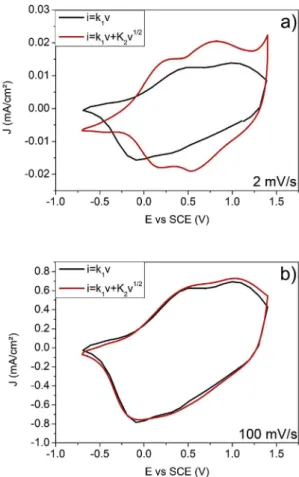
The comparison of the capacitive current calculated from k1 (black line) to the experimental current (red line) depending on the scan rate shows that a significant fraction of the current is attributed to a
Fig. 4. Memory effect of (a) NiO/1:9 LiTFSI-EMITFSI/Pt, (b) NiO/1:9 NaTFSI-EMITFSI/Pt, (c) NiO/EMITFSI/Pt. 1-voltage to reach the reduce state is applied, 2-voltage release (open circuit), 3-voltage to reach the oxidation state, 4-vol-tage release (open circuit).
Table 1
summary of some electrochromic properties of NiO in various electrolytes.
Electrolyte LiTFSI-EMITFSI NaTFSI-EMITFSI EMITFSI
Delta Optical transmittance 56 52 40 Memory effect (%) bleaching 7 8 6
coloration 3 2 3
Switching time (s) T bleach 1.5 1.5 2
capacitive contribution (Fig. 7). At higher sweep rates (100 mV/s) dif fusion controlled currents are unable to contribute to the total current because of their slower time response. Therefore, it is not surprising that at 100 mV/s, both curves are very close. Moreover, for all of the electrolytes, the capacitive contribution to the total current will in crease with sweep rate as there is progressively less contribution from diffusion controlled processes (Fig. 8).
Regardless of the electrolyte, the charge storage associated with capacitive processes is in the range of 9 mC/cm2(Fig. 8). This capacity can be attributed to surface adsorption effects linked to EMI+ and
TFSI−ions. For this reason, the charge storage and charge transfer at the surface are favored as the sweep rate increases. Thus, even with salt free electrolytes such as EMITFSI, the capacitive contribution to the total current remains constant as a function of sweep rate because there is no significant diffusion expected for EMI or TFSI. Noneless to remind
that, the contribution of both anions and cations was earlier suggested by EC behavior with departure in oxidation. In addition, the absence of ion insertion was confirmed by the fact that no shift of the 111 peak was observed.
3.2.4. Cycling of NiO thinfilms in [ 0.7 to 0.4 V] and [0.4 V 1.2 V] regions The cycling of NiO films in different voltage regimes is able to provide additional insights regarding the EC mechanism. NiO thinfilms were cycled in two different voltage regions, namely between and 0.4 V and 1.2 V and in between−0.7 V and 0.4 V, considering a three elec trode cell using SCE electrode as reference electrode.Fig. 9shows the electrochemical and optical behavior of NiO thinfilms cycled between −0.7 V and 0.4 V after an initial cycle to 0.6 V. As expected, the de crease in the upper voltage from 0.6 V to 0.4 V initially corresponds to an increase in the transmittance value (shown as the change from the blue to green dot in Fig. 8b). Upon cycling, the transmittance pro gressively decreases from 70 to 65 % confirming a greater level of oxidation as indicated by the increase in current density. The latter should be correlated to a gradual lithium insertion. In contrast, a limit in the reduction potential by cycling in the 0.4 V 1.2 V window leads to a slightly higher transmittance value from 42 to 47 % in oxidation while a rather constant value close to 60 % is reached at 0.4 V (Fig. 10). An optical contrast of 12.5 % is observed in this potential window. In addition, in this voltage range, the rectangular shape which is observed is characteristic of either double layer capacitance effects or pseudo capacitance.
3.3. PANI/NiO device
Investigations of EC behavior of NiO thinfilms in lithium, sodium and cation free electrolytes conclude on two competing phenomena leading to consider a pseudocapacitive behavior for NiO thin films. Such identification of a more complex EC mechanism offers opportunity to consider EC devices with unusual architecture. Indeed in our group,
Fig. 5. Voltammetry cyclic of (a) WO3/LiTFSI-EMITFSI/Pt and (b) NiO/LiTFSI-EMITFSI/Pt at different scan rate and the corresponding In-situ transmittance vs time
at the wavelengths of 550 nm, (c) WO3/LiTFSI-EMITFSI/Pt (d) NiO/LiTFSI-EMITFSI/Pt.
Fig. 6. ratio of capacity (xmV/s/2mV/s) at various scan rate of NiO and WO3thin
we recently develop new device architectures by using a white elec trolyte aiming at displays applications. A further step forward was achieved by modifying the electrochromic layer by mixing oxides with commercial polymer inks for higher performance hybrid electrodes [22]. The concept of hybrid device can be extended not only to single electrode but to the combination of a polymer electrode and an oxide one. Herein, the possibility of cycling in NiO in cations free electrolyte is further extended to hybrid architecture based on a white membrane. Besides, in respect of current research in thefield of batteries, avoiding Li for resources purpose, the ability to cycle in lithium free electrolyte was evaluated in a full device using a EMITFSI PMMA membrane and polyaniline (PANI), which is one of the commonly used conductive polymers, as second electrode (Fig. 11) [23]. The PANIfilm was elec trodeposited from a solution of H2SO41 M and 0.1 M of aniline using a
potential of 1 V for 3 min. The excess material was removed by ethanol. The good cyclibility of the PANI layer in EMITFSI electrolyte was confirmed in three electrodes cell configuration. For building the de vice, the electrolyte consists of a white membrane soaked over one night in EMITFSI [24]. The association of NiO and PANI led to the following device:
ITO/PANI/EMITFSI white membrane/NiO/ITO
Prior to device assembly, each layer was activated in the 0.8 V 1.2 V window, 50 times for NiO and 6 times for PANI. The PANI/NiO device has been cycled one hundred times between−0.7V and 0.8V showing a simultaneous color change from transparent (appearing whitish due to the electrolyte membrane) to brownish on the NiO side and from dark to light green on the PANI side (Fig. 11). The CVs from 2 to 100 cycles show a rather featureless shape with a limited decrease in capacity. The
optical contrasts of the two faces were evaluated using the L*a*b* color system. It is worth recalling that in CIE colorimetric space, the color is represented by three parameters: a luminance axis (L*) and two hue axes (a*) and (b*), which can be used to define and compare quanti tatively the colors. The optical contrastΔE* is presented by this equa tion
ΔE* = [(L*c−L*b)2+ (a*c− a*b)2+ (b*c− b*b)2]½ (6)
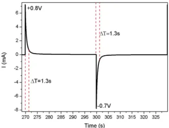
CloseΔE* values were determined for both sides, namely 14.6 for NiO and 14.4 for PANI at the inception of cycling. With more extended cycling, the value slighty decreases to 12.1 after 50 cycles for NiO and remains constant for PANI. Chronoamperograms, recorded for 30 s at 0.8 V and 30 s at−0.7 V for 20 times (Fig. 12), show a fast switching time of 1.3 s.
Fig. 7. Voltammetric response (2 mV/s and 100 mV/s) for NiO/LiTFSI-EMITFSI/Pt vs SCE. The total current (red line) is obtained experimentally. The capacitive currents (black line) are determined from the eq. (For interpretation of the references to color in thisfigure legend, the reader is referred to the Web version of this article.)
Fig. 8. Capacitive capacity (black) and total capacity (grey) vs scan rate (a) NiO/LiTFSI-EMITFSI/Pt (b) NiO/NaTFSI-EMITFSI/Pt, (c) NiO/EMITFSI/Pt.
4. Conclusion
Despite, numerous years of study and their integration in commer cialized devices, the electrochromic mechanism occurring in NiO thin films is still the subject of debate. In this paper, RF sputtered NiO thin
films were cycled in various ionic liquid electrolytes based on EMITFSI that contained LiTFSI, NaTFSI or were neat. At first glance, the EC properties of NiO, that is, the electrochemical behavior and optical contrast appear only slightly affected by the electrolyte nature with a transmittance modulation between 40 (EMITFSI) to 56 % (LiTFSI) and a colorless to brownish switch. To gain greater insight of the EC me chanism, we used an analytical approach to separate the current into contributions which were diffusion controlled or capacitor like in nature. The results suggest that a pseudocapacitive mechanism is con tributing to the electrochromic response of NiO. Redox reactions oc curring at the surface or near surface of NiO in response to the ad sorption or slight insertion of Li+, Na+, EMI+or TFSI−are responsible
for the charge transfer reactions that produce the coloration effects. Integration of NiO thinfilms in a full device is illustrated in double sided PANI/white electrolyte/NiO EC devices which exhibit simulta neous progressive color changes from dark to light green and white to brown.
Acknowledgments
The authors wish to thank the University of Bordeaux for funding this research and in particular the Ph. D. grant of M. Da Rocha. Bruce Dunn wishes to thank the LabEx AMADEus (ANR 10 LABX 42) in the framework of IdEx Bordeaux (ANR 10 IDEX 03 02), i.e. the Investissements d’Avenir programme of the French government managed by the Agence Nationale de la Recherch, for supporting his invited professor fellowship.
References
[1] N.L. Sbar, L. Podbelski, H.M. Yang, B. Pease, Electrochromic dynamic windows for office buildings, Int. J. Sustain. Built Environ. 1 (2012) 125–139.
[2] E. Wesoff, View Has Raised More than $500 Million for Smart Adaptive Windows, (2015) Available at: https://www.greentechmedia.com/articles/read/view-has-raised-more-than-500-million-for-smart-adaptive-windows Accessed: 25th January 2018.
[3] D.T. Gillaspie, R.C. Tenent, A.C. Dillon, Metal-oxidefilms for electrochromic ap-plications: present technology and future directions, J. Mater. Chem. 20 (2010) 9585–9592.
[4] M. Mihelčič, A.Š. Vuk, I. Jerman, B. Orel, F. Švegl, H. Moulki, C. Faure, G. Campet, A. Rougier, Comparison of electrochromic properties of Ni1 xO in lithium and
li-thium-free aprotic electrolytes : from Ni1 xO pigment coatings toflexible
electro-chromic devices, Sol. Energy Mater. Sol. Cells 120 (A) (2014) 116–130. [5] T. Kubo, Y. Nishikitani, Y. Sawai, H. Iwanaga, Y. Sato, Y. Shigesato, Electrochromic
properties of LixNiyOfilms deposited by RF magnetron sputtering, J. Electrochem.
Soc. 156 (2009) H629–H633.
[6] S. Passerini, B. Scrosati, Electrochromism of Thin-Film Nickel Oxide Electrodes, Solid State Ion, vols. 53–56, (1992), pp. 520–524.
[7] Y.-S. Lin, D.-J. Lin, L.-Y. Chiu, S.-W. Lin, Lithium electrochromism of atmospheric pressure plasma jet-synthesized NiOxCythinfilms, J. Solid State Electrochem. 16 (8) Fig. 9. NiO thin films cycled in NiO/1:9 LiTFSI-EMITFSI/Pt vs SCE using a
10 mV/s scan rate and 0.7V–0.4V voltage window and (b) in-situ transmit-tance vs time at the wavelengths of 550 nm.
Fig. 10. NiO thinfilms cycled in NiO/1:9 LiTFSI-EMITFSI/Pt vs SCE using a 10 mV/s scan rate and 0.4V–1.2V voltage window and (b) in-situ transmittance vs time at the wavelengths of 550 nm.
Fig. 11. Voltammetry cyclic of the device NiO/white membrane-EMITFSI/ PANI at 20 mV/s.
Fig. 12. Chronoamperometry of the device NiO/white membrane-EMITFSI/ PANI (+0.8V (30s)/-0.7V (30s)).
(2012) 2581–2590.
[8] S. Green, J. Backholm, P. Georén, C.G. Granqvist, G.A. Niklasson, Electrochromism in nickel oxide and tungsten oxide thinfilms: ion intercalation from different electrolytes, Sol. Energy Mater. Sol. Cells 93 (12) (2009) 2050–2055.
[9] H. Huang, J. Tian, W.K. Zhang, Y.P. Gan, X.Y. Tao, X.H. Xia, J.P. Tu, Electrochromic properties of porous NiO thinfilm as a counter electrode for NiO/WO3
com-plementary electrochromic window, Electrochim. Acta 56 (2011) 4281–4286. [10] H. Moulki, C. Faure, M. Mihelcic, A. Surca Vuk, F. Svegl, B. Orel, G. Campet,
M. Alfredson, A.V. Chadwick, D. Gianolo, A. Rougier, Electrochromic performances of nonstoichiometric NiO thinfilms, Thin Solid Films 553 (2014) 63–66. [11] R.-T. Wen, C.G. Granqvist, G.A. Niklasson, Anodic electrochromism for
energy-ef-ficient windows: cation/anion-based surface processes and effects of crystal facets in nickel oxide thinfilms, Adv. Funct. Mater. 25 (2015) 3359–3370.
[12] I. Mjejri, R. Grocassan, A. Rougier, Enhanced coloration for hydrid niobium based electrochromic devices, ACS Appl. Energy Mater. 1 (8) (2018) 4359–4366. [13] I. Mjejri, C.M. Doherty, M. Rubio-Martinez, G.L. Drisko, A. Rougier, Double-sided
electrochromic device based on metal-organic frameworks, ACS Appl. Mater. 9 (46) (2018) 39330–39934.
[14] A. Anders, A structure zone diagram including plasma-based deposition and ion etching, Thin Solid Films 518 (15) (2010) 4087–4090.
[15] M. Da Rocha, Y. He, X. Diao, A. Rougier, Influence of cycling temperature on the electrochromic properties of WO3//NiO devices built with various thicknesses, Sol.
Energy Mater. Sol. Cells 177 (2018) 57–65.
[16] S.-H. Lee, H.M. Cheong, Electrochromic mechanism in a-WO3 ythinfilms, Appl.
Phys. Lett. 74 (1999) 242–244.
[17] J. Wang, E. Khoo, P.S. Lee, J. Ma, Synthesis, assembly, and electrochromic prop-erties of uniform crystalline WO3nanorods, J. Phys. Chem. C 112 (2008)
14306–14312.
[18] D. Ma, T. Li, Z. Xu, L. Wang, J. Wang, Electrochromic devices based on tungsten oxidefilms with honeycomb-like nanostructures and nanoribbons array, Sol. Energy Mater. Sol. Cells 177 (2018) 51–56.
[19] V. Augustyn, P. Simon, B. Dunn, Pseudocapacitive oxide materials for high-rate electrochemical energy storage, Energy Environ. Sci. 7 (2014) 1597–1614. [20] J. Wang, J. Polleux, J. Lim, B. Dunn, Pseudocapacitive contributions to
electro-chemical energy storage in TiO2(anatase) nanoparticles, J. Phys. Chem. C 111
(2007) 14925–14931.
[21] R. Giannuzzi, R. Scarfiello, T. Sibillano, C. Nobile, V. Grillo, C. Giannini, P.D. Cozzoli, M. Manca, Enhanced efficiency of the honeycomb-structured film WO3 composed of nanorods for electrochromic properties, 41 (2017) 634–645. [22] P. Yogi, Organic nanostructures on inorganic ones : an efficient electrochromic
display by design, ACS Appl. Nano Mater. 1 (7) (2018) 3715–3723.
[23] H. Wang, J. Lin, Z.X. Shen, Polyaniline (PANi) based electrode materials for energy storage and conversion 1 (3) (2016) 225–255.
[24] L.J. Goujon, A. Khaldi, A. Maziz, C. Plesse, G.T.M. Nguyen, P.-H. Aubert, F. Vidal, C. Chevrot, D. Teyssie, Flexible solid polymer electrolytes based on nitrile butadiene rubber : poly(ethylene oxide) interpenetrating polymer networks containing either LiTFSI or EMITFSI, Macromolecules 44 (24) (2011) 9683–9691.