HAL Id: hal-02824576
https://hal.inrae.fr/hal-02824576
Submitted on 6 Jun 2020HAL is a multi-disciplinary open access archive for the deposit and dissemination of sci-entific research documents, whether they are pub-lished or not. The documents may come from teaching and research institutions in France or abroad, or from public or private research centers.
L’archive ouverte pluridisciplinaire HAL, est destinée au dépôt et à la diffusion de documents scientifiques de niveau recherche, publiés ou non, émanant des établissements d’enseignement et de recherche français ou étrangers, des laboratoires publics ou privés.
Eric Rigolot, François de Coligny, Philippe Dreyfus, Jean-Luc Dupuy, Isabelle
Lecomte, Boris Pezzatti, Oana Vigy, François Pimont
To cite this version:
Eric Rigolot, François de Coligny, Philippe Dreyfus, Jean-Luc Dupuy, Isabelle Lecomte, et al.. FUEL MANAGER: a vegetation assessment and manipulation software for wildfire modeling. 6. Interna-tional Conference on Forest Fire Research, Nov 2010, Coimbra, Portugal. 12 p. + poster. �hal-02824576�
F
UEL
M
ANAGER
: a vegetation assessment and manipulation
software for wildfire modeling
Eric Rigolot
National Institute for Agronomic Research (INRA), Mediterranean Forests Ecology Research Unit (UR629), Site Agroparc, Domaine Saint Paul, 84914 Avignon cedex 9,
France, [email protected]
François de Coligny
INRA, UMR AMAP, Montpellier, France, [email protected]
Philippe Dreyfus
INRA, UR629, Avignon, France, [email protected]
Jean-Luc Dupuy
INRA, UR629, Avignon, France, [email protected]
Isabelle Lecomte
INRA, UR629, Avignon, France, [email protected]
Boris Pezzatti
WSL, Swiss Federal Research Institute, Bellinzona, Switzerland, [email protected]
Oana Vigy
INRA, UR629, Avignon, France, [email protected]
François Pimont
INRA, UR629, Avignon, France, [email protected]
Abstract
The FUEL MANAGER is a CAPSIS module that is devoted to fuel modeling, fuel build-up and fire effect assessment. The CAPSIS platform (http://www.inra.fr/capsis) is a software package designed to host forestry models, either growth and yield or dynamics models. In the FUEL MANAGER, fuel modeling is based on a description of the physical properties of the thin particles (leaves, twigs) involved in fire propagation. Three-dimensional scenes can be built and visualized and different kinds of objects can be added to represent both trees and the undergrowth. Each object contains different data from particles properties (mass to volume ratio, surface to volume ratio of leaves and twigs) to bulk density 3D distributions. Tree description is based on allometric relationships between diameter at breast height and leaves or twig biomasses, tree crown shape models, and horizontal and vertical biomass distributions. The physical properties of the different species are based on empirical models or field data downloaded remotely from an object-oriented database. The 3D scene can also be built from input files with various types of format. The fuel scenes can be exported in a format readable by the fire behavior physically-based model FIRETEC. This model requires fuel data (bulk
densities, leaf area and fuel moisture content) spatialized in 3D voxels, at a resolution close to 2m. The FUEL MANAGER also enables to simulate fuel build-up and fuel management. Tree growth
models account for the effects of site conditions, stand age and competition between trees, as well as management effects (thinning, pruning). They predict competition-induced mortality and the evolution of tree stem diameter, total height, crown height and width. Fuel treatments can be applied to all or part of the scene to reduce appropriately the local biomass available. Fire effects can be derived from empirical models. Based on a scenario of fire intensity and residence time in the stand, crown scorch, crown kill and damage to bark are computed for each individual tree using a variety of published empirical models. These computed damages are then used to assess the tree mortality probability, based on logistic models. Damages to crown and bole can be visualized in the 3D frame. The FUEL MANAGER is a very promising tool for the investigation of fuel management scenarios. It
is based on recent technologies for visualization and scene manipulation and on recent research results for fuel and fire effect modeling.
Keywords: Fuel modeling, Stand dynamics, FIRETEC, Fire effect
1. Introduction
Fuel is a key component of fire environment and a central parameter for assessing fire ignition, fire behavior and fire effects. Fuel together with weather and topography are determining factors for predicting fire behavior (Chandlers et al., 1983). In that respect, fuel can be considered, on the short range, as a structural factor for assessing fire risk.
On the long range, fuel build-up is part of the basic processes of ecosystem dynamics although forest science allocates much more effort on tree growth and yield models than on undergrowth dynamics studies. Nevertheless, knowledge about grass and shrub layers is a fundamental of wildland fire management, since they contribute to potential fire behavior and will decide whether a surface fire will develop into a crown fire (Scott and Reinhardt, 2001). On a dynamical perspective, environmental conditions and fire regime, together with fire effects and post-fire dynamics, will explain the role of fire as a perturbation in changing the ecosystem trajectories (Dale et al., 2001).
Wildfire is a human driven phenomenon, at least in the Mediterranean environment (Rego et al., 2010), and wildfire prevention relies on human actions as well, since fuel modification is the main option for changing fire behavior (Fernandes and Botelho, 2003). Chandlers et al. (1983) describes the strategies for fuel management, the most used being load reduction, compactness increase and discontinuities in horizontal and vertical distributions. Strategies for wildfire hazard abatement need to be assessed including in their consequences on shifting the fire regime.
With this objective, computer simulations combining models of fuel description, fire behavior, fire effects and ecosystem dynamics have been implemented successfully (e.g. Fernandes and Botelho, 2003), but an integrated simulation platform able to link the various models involved in a single tool, is still missing. The Fire and Fuels Extension (FFE) to the Forest Vegetation Simulator (FVS) (Reinhardt and Crookston, 2003) is an advanced tool to simulate fuel dynamics and potential fire behaviour over time, in the context of stand development and management. Coupled with the Stand Visualisation System (SVS) (McGaughey, 1997; http://www.fs.fed.us/pnw/svs/), it is an integrated solution, but not compatible with the last advances in fire behaviour modelling.
The FUEL MANAGER has been specially designed for interacting with tridimensional
physically-based fire propagation models. These models (Linn et al., 2005; Mell et al., 2007) include 3D representation of fuels, which is a critical advance to investigate the impact of heterogeneous fuel types and transitions between fuel types, compared to previous models such as BEHAVE (Rothermel, 1972). Physically-based fire models require
fuel data that are spatialized in 3D voxels. To the best of our knowledge, no tool was yet available to build vegetation scene in 3D. Parsons (2006) has developed a software called FUEL3D, based on fractal representation of trees. However, this tool does not have the
functionality to build large scenes, with different fuel types including the undergrowth. This paper gives an overview of the FUEL MANAGER abilities and functionalities. It presents the main features for building 3D vegetation scenes, for creating 3D spatially explicit fuel models and for displaying fire impacts on vegetation as a result of the application of various models of fire effects.
2. FUEL MANAGER structure
2.1. A CAPSIS module
The CAPSIS platform is a software package (http://www.inra.fr/capsis) designed to
hosting forest growth and dynamics models (de Coligny, 2007). Such a tool is very convenient for forestry modelers, managers and education. CAPSIS is designed around a
kernel which provides an organizational data structure (session, project, scenario, steps) and also generic data descriptions (stand, tree, etc.).
Under a given project, different simulations can be run to investigate several scenarios of stand evolution. Each simulation history contains different steps to describe stand evolution, human interventions and ecological perturbations. A simulation always contains a root step, describing the initial stand, either loaded from file or virtually generated. A project memorizes the different steps of the simulation history. A project manager displays the several scenarios simulated for a given project, and offers tools for stand manipulation and visualisation (Figure 1). The project manager provides a step contextual menu containing step management options like thinning, pruning, fertilization, plantation, or software features like viewers, graphics or export tools in various formats.
The FUEL MANAGER is a CAPSIS module that is devoted to fuel modelling, fuel build-up and fire effect assessment. One of the main goals of this software is to interact with physically-based fire behavior models (Lecomte et al., 2010).
2.2. Vegetation scene
Vegetation objects
A vegetation scene is composed of several objects including a terrain, a grid, and several vegetation objects. A terrain corresponds to the ground of a vegetation stand. A grid is a set of lines dividing the ground surface in squares. It can be useful for locating vegetation objects in the vegetation scene.
The vegetation objects represented on a vegetation scene can be used to build a large variety of landscapes, including zones with different fuel types. Vegetation objects can be either fuel layers or individual plants like trees or shrubs. A fuel layer is a collection of individual plants, closely grouped and difficult to describe separately, inviting the user to summarize them in a unique object. A fuel layer is attached to a polygon, which locates the fuel complex on the vegetation scene. A fuel layer can be simple or composed of several elementary fuel layers. In the last case, it is called a fuel layer set. For example, a Grassland is generally represented with a simple fuel layer because it only contains one layer of grass, whereas a Mediterranean garrigue is generally represented with a fuel layer set because it can contain 3 different fuel layers: Quercus coccifera, Rosmarinus officinalis and
Brachypodium retosum. Fuel layers are generally used to represent the undergrowth, but
can be also used to represent canopies.
Each vegetation object is described with its own attributes and macroscopic properties. Individual plant attributes include species name, position (x,y,z), stem diameter, total height, crown base height, crown diameter, height of maximum crown diameter, crown profile, bulk density, leaf area index, fuel moistures of the several fuel particle categories, and some fire effects descriptors. A fuel layer set is described as a single vegetation object, including a list of layers. Each layer has almost the same properties than
an individual plant, but has also additional specific attributes like cover fraction and characteristic size of clumps.
Figure 1. The project manager with 3 scenarios in a Pinus halepensis Mill. stand separated by a forestry road (in black). The top part represents the different steps (in year) in the different scenarios, starting from a same initial stand (0a), visualized below (top left 3D viewer). The different scenarios represent (a) a natural evolution during 6 years, (b) an undergrowth clearing and tree thinning (5 m between crowns) on a 100 m wide zone, followed by 6 years of evolution and (c) an undergrowth clearing and tree thinning (5 m between crowns) on a 100 m wide zone, followed by 3 years of evolution and a fire (750 kW/m). Post fire damages are displayed on the bottom left 3D viewer, as well as some statistics on the bottom right graph with dead trees grouped by diameter classes (in red), compared to initial number of trees (in blue).
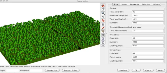
The FUEL MANAGER module includes a 3D scene editor. Individual plants are
represented as individual objects, with a crown shape, whereas a fuel layer set is represented by a volume, which section is the polygon attached to the fuel layers and the height is the maximum height of the layers contained in the fuel layer set (Figure 2).
Figure 2. The main window of the FUEL MANAGER, containing a 3D visualization of an
Aleppo pine stand with a 10 m wide forest road, and its control panel on the right.
Vegetation scene creation
A scene can be created from text files of various formats containing the description of fuels in terms of individual plants or fuel layers and can be edited and modified. Polylines and polygons can be added in the scene as well as fuel objects (plant, layers) with the “add” icon. A scene can be built from scratch, only using the “add” icon.
Several creation modes for generating a vegetation scene are currently available throughout the user interface, respectively from vegetation inventories, from field parameters, from scratch (empty scene) or from a scene previously saved.
The scene generation through a database inventory uses an inventory file which contains only vegetation objects known in FUELWEB, a web-based object-oriented database
(Krivtsov et al., 2009). The inventory file describes each vegetation object throughout its “ID” in the FUELWEB database, and location. This option requires a connection with the remote database since species, height and crown dimensions are read for each fuel in the database before generating the scene. The inventory file also contains a line describing the dimensions of the terrain. Using this option to generate a vegetation scene will make possible the creation of export files necessary to run the fire propagation model.
The next two loaders doesn’t require any access to the FUELWEB database as the
vegetation object doesn’t contain the vegetation object “ID” of the database. Individual plants biomasses are generated by allometric relationships. A detailed inventory file can be loaded as well which describes each vegetation object in details throughout its species, crown dimensions and location. The “Popcov” sub options enable to generate automatically several tree or shrub populations by using some intra and inter populations spatial rules and constraints. As described by Goreaud et al. (2002), spatial rules use namely Gibbs parameter. The “From field parameters” option is useful to generate automatically a vegetation scene, given some indications describing its structure and composition. It may contain a list of dominant tree species (with specific heights and DBH classes) and a list of fuel layer sets including their respective fuel layers for the description of the undergrowth (height, cover, bulk density, moisture content …).
3D scene editor
The 3D scene editor was designed to visualize and edit the vegetation scene (Figure 2). The main window of the editor is divided into several functionally independent zones: a 3D view panel of the scene (left), a menu bar, a tool bar and a real time control panel (right). The view on the scene can be modified using the first top three icons (“orbit”, “translate” and “zoom”) and the mouse. General properties of the scene are displayed in the control panel, including cover fraction, phytovolume of the undergrowth and fuel load.
Any item (terrain, grid and vegetation objects) of the vegetation scene can be visualized in different ways thanks to several renderers. As renderers are CAPSIS
extensions, the FUEL MANAGER module needs only to match extensions to be able to use them. So, “Bounding Boxes”, “Lollipops” and “Grid” renderers are used as they were released in CAPSIS; it implies to adapt some functionalities to the FUEL MANAGER
requirements. On the contrary, the “Pattern Sketcher” renderer was especially developed for the FUEL MANAGER purposes. This renderer permits to visually differentiate categories of vegetation objects using various geometric shapes of tree crowns. A colour setting enables further details in vegetation classification display. Rendering mode can be modified in the control panel and the attributes of the selected plants can be seen with the “Edition” tab.
Any vegetation object can be edited and modified. Several planting processes or methods to display vegetation objects on the scene are available including interacting planting using the mouse, planting along a line or in rows or some random patterns.
Special attention has been paid to the robustness and efficiency of scene manipulation, because 3D visualization is a costly technology and items displayed on the vegetation scene can be very numerous. First, a degraded mode based on skeleton of tree crown is used by default during view manipulation (fast mode). Second, the rendering of trees is degraded when tree number is high, so that scene manipulation is maintained. The quality of this representation can be temporary increased for more accurate visualization. The FUEL MANAGER was also designed to support heavy scenes with significant numbers of trees. The whole plot of the International Crown Fire Modelling Experiment (Alexander et
al., 2004) has been represented and manipulated with more than a million of trees.
3. Fuel modelling
3.1. Detailed 3D structure of fuel objects
Each fuel object (individual plant or layer) can be associated to a detailed representation of its 3D structure, so that it can be exported to any kind of fire model that uses an explicit 3D representation of the fuel. This structure is based on a description of the vegetation object in small voxels. By small, we mean significantly smaller than the object size (generally one tenth), so that the object 3D structure is reasonably well described. Voxel size depends on the method used to fill the voxels (data base samples derived from cube method, allometric tree models ...). The voxels of the 3D matrix of a fuel object contain different local properties, including fuel volume (m3), live and dead fuel biomasses (kg), surface area (m2) and live and dead fuel water mass (kg).
3.2. Fire Paradox database manager (individual plants and fuel layers)
The cube method is a fuel description method proposed by Cohen et al. (2002) to model the spatial distribution of fuel particles as required by physically based fire
propagation models. Individual shrubs or fuel layers are modeled using a limited set of voxels sampled in the field where fuel particles are sorted by class sizes and measured in biomass and for assessing their main thermal, chemical and physical properties. Fuel sampling is generally carried out on elementary voxels of 25 cm side. Field description includes an assessment of plant geometry and of the distribution of voxel types within the plant shape (Krivtsov et al., 2009). This fuel modeling method is specially adapted to shrubs smaller than 3 meters in height.
Data related to fuel description are stored the FUELWEB database, which structure
with particle as a central class has been chosen as the best strategy to encompass the fuel data high heterogeneity in scales and organization modes (Krivtsov et al., 2009). The database has the potential to store and process the wide range of fuels data. The database is part of the European Fuel Knowledge Platform implemented by the FIRE PARADOX
European project and located on the European Forest Institute server in Joensuu, Finland. The FUEL MANAGER is remotely connected to the FUELWEB database via an automatic Internet connection. A set of dialog windows have been implemented on the FUEL
MANAGER to manage the interactions with the FUELWEB database. FUEL MANAGER being a
fully integrated tool, interactions are considered in both ways (i) for extracting fuel information from the database in order to display it on the vegetation scene, but also (ii) for storing new plants or updating any fuel information in the database. Fuel information may be related either to a measured plant corresponding to a real plant measured in the field, or to a virtual plant, created with the FUEL MANAGER. A virtual plant may differ from a real one either by its shape, by the distribution of voxels (fuel samples) within its shape, or by the values of one or several fuel parameters (e.g. mean of several samples).
Extracting fuel information from the FUELWEB database
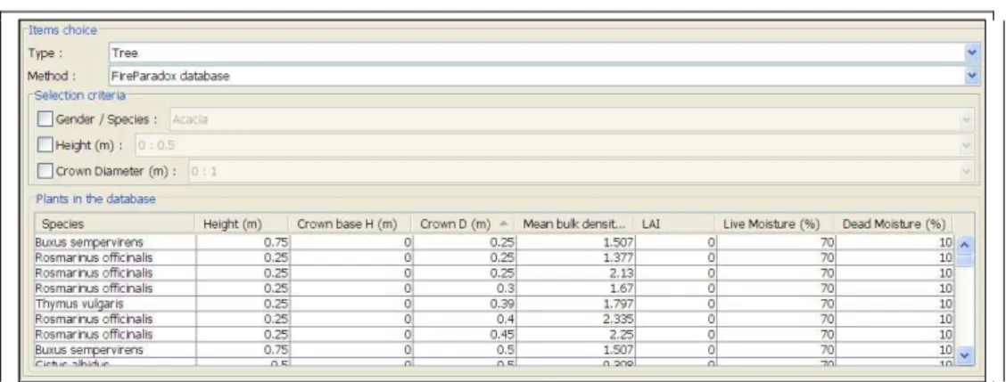
Each vegetation object of the scene can be associated to a detailed representation of its 3D fuel structure, so that it can be exported to any fire model that uses an explicit 3D representation of the fuel. When selecting the “Fire Paradox database” option in the dialog windows for planting new individual plants or fuel layers on the vegetation scene, a list of available vegetation objects is displayed with some selection criteria (Figure 3).
Figure 3. A fuel plant list extracted from the FUELWEB database for selecting
plants to be managed by the FUEL MANAGER.
Updating fuel information stored in the WEBFUEL database
The complete process for storing new individual plants or fuel layers in the WEBFUEL database or updating any fuel information can be operated from the FUEL
description of the general information about the sampled plant (species, location, site conditions and history, …), (ii) the description of the elementary samples related to that plant (positions of the voxel types in the column, particle biomasses), (iii) the description of the 2D shape of the sample plant and finally (iv) the generation of the plant 3D shape with voxel types distributed within it. The 3D shape can be generated either by copying voxel types from a sample or a 2D shape, or by using a rotation algorithm from 2D to 3D. In this last case, the shape will be composed of voxels, all different, with biomass values depending on the voxel distance to the centre of the rotation axe. The full process for managing information stored in the WEBFUEL database is described in Lecomte et al.
(2010) and includes the adaptation of the above described method for fuel layers. 3.3. Allometric approach for trees
Allometric models can be used to fill the 3D matrix of fuel objects of some species. These models are generally based on a dendrometric property of the tree, such as the diameter at breast height or the tree total height. To compute fuel volume, fuel surface and water mass in each voxel, it requires three categories of information, respectively (i) a model for the crown envelope, (ii) a model for fuel mass in the envelope, and (iii) additional properties such as moisture content, fuel density and area to volume ratio (Alexander et al., 2004; Mitsopoulos and Dimitrakopoulos, 2007).
Allometric approach includes the branching models which describe the fuel on each branch instead of describing it in each crown. Branching models (see for example Meredieu
et al., 1998) are often built aiming at taking into account the defects induced by branches
(position, size, number, and condition - sound or not - of knots) in wood quality assessment, especially in relation to tree and stand conditions. Statistical models are used to determine the branch distribution in each tree of the stand, depending on the stand history, including management. Then the fuel properties of each branch are assessed based on the same kind of relationships as described for trees, but at the scale of branches, to assess the 3D matrix of the tree.
3.4. Undergrowth models for fuel layers and fuel layer sets
Undergrowth vegetation is generally described as a fuel layer, composed of different fuel families with different properties. Based on some field data, some models has been derived to provide bulk density of a species as a function of height (Cassagne et al., 2009).
Some predefined models of fuel layer sets have also been defined, to assist the user that does not have the details of the fuel complex descriptions. These models are based on a classification defined by Jappiot et al. (2010).
4. Stand evolution and intervention
Among the various management options, the user can choose (i) to compute an evolution of the stand from a given step for a given number of years, (ii) to compute an intervention (pruning, thinning, clearing, etc.) or a perturbation like a fire event or (iii) to export the current step in a given format.
In the case of an evolution, the model calculates subsequent steps after the starting step. These new steps will have different dates. In the case of an intervention, the user has to parameterize it. A new step (with a “*” indicating it is the result of an intervention) is
added after the chosen step, carrying the stand after intervention (Figure 1). Growth model for Pinus halepensis stands and Quercus coccifera garrigue are currently available in the software.
Fire managers mostly use thinning and pruning, as canopy fuel treatment. Among the variety of thinning possibilities available in CAPSIS, it is possible to simulate a thinning
that respaces stems or crowns. Pruning is also available. Generally, interventions are applied to a group of trees or to a spatial location, which can be defined with a variety of criteria. For example, the fuel-break presented on Figure 1 was build with a respacing of crowns at 3 m starting from an initial stand density of 800 stem/ha.
Fire perturbation is a specific case of intervention on the vegetation stand. This functionality enables to calculate the fire impacts on the vegetation objects and namely on trees. Two main options are available, respectively using the outcomes of the FIRETEC fire
propagation model or using some published empirical models relating fire behaviour parameters to fire effects on trees. The export option requires exporting first the vegetation scene in order to run a FIRETEC simulation (see below). The result of a fire spread in terms
of fire effects can be computed, as a function of different parameters (intensity and residence time, rate of spread and residence time, etc.). It results in a new step or scenario in stand life. The option implementing empirical models enables to assess the fire severity parameters of each tree (crown scorch/kill height and volume, cambium damage probability, mortality probability, etc). The user can select through combo boxes the empirical model he wants for crown damage (van Wagner, 1977; Saveland and Neuenschwander, 1989; Finney and Martin, 1992; Michaletz and Johnson, 2006), cambium damage (Peterson and Ryan, 1986; Bova and Dickinson, 2005) and mortality probability (Peterson and Ryan, 1986; Ryan and Amman, 1994).
The fire effects derived from these empirical models can be used in stand scenarios. This damage to crown and bole can be visualized in the 3D editor and some data (tree mortality per diameter class, etc.) can be extracted (Figure 1).
An important purpose of the FUEL MANAGER is to export the vegetation scenes to
fire models to assess the fire behavior. The detailed descriptions of fuel objects in their 3D matrix are fine enough to be used for any fire model containing a physical description of the fuel. However, very few fire models are able to take into account explicitly 3D fuel description, FIRETEC and WFDS being among the few available.
FIRETEC is a coupled 3D atmospheric transport/wildfire behavior model being developed initially at Los Alamos National Lab and co-developed by INRA. It uses descriptions of fuel in 3D voxels with a mesh size close to 2 m (homogeneous horizontally, but stretched vertically). Four input files are required, describing bulk density, fuel thickness, moisture mass and fuel height in cell in all voxels of the mesh.
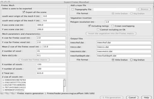
An export option has been developed (Figure 5), in order to build the files for the FIRETEC model. The FIRETEC matrix is generated, according to the dimension of the portion
of the scene that should be exported, mesh size and stretching parameters. Then the 3D matrices of all vegetation objects represented in the scene are built and merged into the FIRETEC matrix. In each voxel of the FIRETEC matrix, the required properties are computed,
according to different options, and are at the end printed in the FORTRAN binary format
Figure 5. Graphical interface of the export to FIRETEC. The left column is dedicated to
FIRETEC mesh computation. The right column contains the options available for export
(inclusion of a topography, resolution of the 3D matrices of fuel objects) and file names.
5. Discussion and conclusion
The FUEL MANAGER is an innovative application dedicated to play a role at the
interface with physically based fire propagation models. Beyond the theoretical interest provided by the use of physics principles and atmospheric science tools, these models can use 3D detailed description of the fuel. This is a critical advance to investigate the impact of heterogeneous fuel types and transitions between fuel types. This is especially important in the context of prevention, for designing fuel treatments and for investigating fuel management scenarios. An export to WFDS (Mell et al., 2007), another well-known 3D physically-based fire model is in project. In the perspective of model outputs comparison, an export to BEHAVE (Rothermel, 1972) could be implemented as well.
On the other hand, the outputs of physically based fire propagation models are promising in terms of fire effects assessment. Fire effects can be directly appraised and visualised with the FUEL MANAGER, using physical and biological models to compute
conduction in bark, convection and radiation in crown, and cellular mortality of cambium and buds.
The FUEL MANAGER is a comprehensive and promising tool which completes the link
between fuel modelling, fire behaviour and fire effects. It is based on recent technologies for visualization and scene manipulation and on recent research results for fuel and fire effect modelling. The CAPSIS license policy makes it possible to share it among a
community of modellers and end-users, so that a good integration of new abilities (export to other fire models) and new species will be possible. The FUEL MANAGER is available for
download at http://fireintuition.efi.int/products.fire.
Acknowledgments
The FUEL MANAGER is a product of the Integrated Project FIRE PARADOX
6. References
Alexander ME., Stefner CN., Mason JA., Stocks BJ., Hartley GR., Maffey ME., Wotton BM., Taylor SW., Lavoie N., Dalrymple GN. 2004. Characterizing the jack pine-black spruce fuel complex of the International Crown Fire Modelling Experiment (ICFME). Can. For. Serv., Northern Forestry Centre, Alberta. Inf. Rep. NOR-X-393. 49p.
Bova AS., Dickinson MB. 2005. Linking surface-fire behavior, stem heating, and tissue necrosis. Canadian Journal of Forest Research 35, 814-822.
Cassagne N., Curt T., Pimont F., Schaffhauser A., Rigolot E., Borniet L., Dupuy JL., Estève R., Ganteaume A., Jappiot M., Martin W., Moro, C., N’Diaye A., Petit P., Portier D., Valette J.C. 2009. Fuel and modelling. Internal Report 3.4-4 of the Integrated project “Fire Paradox”, Project no.FP6-018505, European Commission, 40p.
Chandler C., Cheney P., Thomas P., Trabaud L., Williams D. 1983. Fire in Forestry, Vol. II: Forest fire management and organization. John Wiley & Sons, N.Y. 298p.
Cohen M., Rigolot E., Etienne M. 2002. Modelling fuel distribution with cellular-automata for fuel-break assessment. In Proceedings of IV International Fire Conference on Forest Fire Research 2002. Wildland Fire Safety Summit, Luso, Coimbra, Portugal, 13-23 November 2002, Millpress Science Publishers, Rotterdam, Netherlands.
Dale V., Joyce L., McNulty S., Neilson R., Ayres M., Flannigan M., Hanson P., Irland L., Lugo A., Peterson C., Simberloff D., Swanson F., Stocks B., Wotton B. 2001. Climate Change and Forest Disturbances. BioScience 51(9): 723-734.
de Coligny F. 2007. Efficient Building of Forestry Modelling Software with the Capsis Methodology. In: Fourcaud T., Zhang XP., eds. Plant Growth Modeling and Applications. Proceedings of PMA06. Los Alamitos, California: 216-222.
Fernandes P., Botelho H. 2003. A review of prescribed burning effectiveness in fire hazard reduction. Int. J. Wildland Fire 12: 117-128.
Finney MA, Martin RE, 1992. Modeling effects of prescribed fire on young-growth coast redwood trees. Can. J. For. Res. 23 (6): 1125–1135.
Goreaud F., Loreau M., Millier C. 2002. Spatial structure and the survival of an inferior competitor: a theoretical model of neighborhood competition in plants. Ecol. Mod. 158: 1– 19
Jappiot M., Alexandrian D., Benjelloun H., Cassagne N., Dupuy JL., Ganteaume A., Hachmi M., Lampin-Maillet C., Pimont F., Rigolot E., Rouch L., Sesbou A., Abdelmoula K., Allgöwer B., Borgniet L., Curt T., Defossé G., Ghosn D., Gitas I., Jimenez E., Kazakis G., Koetz B., Long M., Louis S., Machrouh A., Mårell A., Morge D., Moro C., Morsdorf F., Vega JA., Wellani W. 2009. Guide for characterizing fuels and assessing fuel type’s combustibility. Deliverable D.3.4-5 of the Integrated project “Fire Paradox”, Project no. FP6-018505, European Commission, 92p.
Krivtsov V., Vigy O., Legg C., Curt T., Rigolot E., Lecomte I., Jappiot M., Lampin-Maillet C., Fernandes P., Pezzatti GB. 2009. Fuel modelling in terrestrial ecosystems: an overview in the context of the development of an object-orientated database for wildfire analysis.
Lecomte I., de Coligny F., Griffon S., Pimont F., Rigaud E., Rigolot E., Vigy O. 2010. Fire Paradox Fuel Manager: User’s manual Final Product P6.1-6 of the Integrated project “Fire Paradox”, Project no. FP6-018505, European Commission, 83p.
Linn RR., Winterkamp J., Colman JJ., Edminster C., Bailey J., 2005. Modeling interactions between fire and atmosphere in discrete element fuel beds. Int. J. Wildland Fire 14: 37-48. McGaughey RJ. 1997. Visualizing forest stand dynamics using the stand visualization system. In: Proceedings of the 1997 ACSM/ASPRS Annual Convention and Exposition; April 7-10, 1997; Seattle, WA. Bethesda, MD, 4: 248-257.
Mell W., Jenkins MA., Gould J., Cheney. 2007. A physics-based approach to modelling grassland fires. Int. J. Wildland Fire 16: 1-22.
Meredieu C., Colin F., Hervé JC. 1998. Modelling branchiness of corsican pine with mixed-effect models (Pinus nigra Arnold SSP. Laricio (Poiret) Maire). Ann. Sci. For. 55: 359–374.
Mitsopoulos ID., Dimitrakopoulos AP. 2007. Allometric équations for crown fuel biomass of Aleppo pine (Pinus halepensis Mill.) in Greece. Int. J. Wildland Fire 16: 642-747.
Parsons RA. 2006. Fuel 3D: a spatially explicit fractal fuel distribution model. In: ‘Fuels Management – How to Measure Success: Conference Proceedings’, 28–30 March 2006, Portland, OR. (Eds PL Andrews, BW Butler) USDA Forest Service.
Peterson DL., Ryan KC. 1986. Modeling post-fire conifer mortality for long-range planning. Env. Manag. 10: 797-808.
Rego F., Silva JS., Fernandes P., Rigolot E. 2010. Solving the Fire Paradox – Regulating the wildfire problem by the wise use of fire. In: Silva et al. (ed.) Towards Integrated Fire Management – Outcomes of the EU Project Fire Paradox. EFI Res. Rep. 23: 220-228. Reinhardt E., Crookston NL. (Ed.) 2003. The Fire and Fuels Extension to the Forest Vegetation Simulator. Gen. Tech. Rep. RMRS-GTR-116. Ogden, UT: U.S. Department of Agriculture, Forest Service, Rocky Mountain Research Station. 209p.
Rothermel RC. 1972. A mathematical model for predicting fire spread in wildland fuels. USDA Forest Service Research Paper INT-115. Intermountain Forest and Range Experiment Station, Ogden, UT.
Ryan KC., Amman GD. 1994. Interactions between fire-injured trees and insects in the greater Yellowstone area. Plants and their Environments. In: US Department of Interior and National Park Service (ed.), Book of Proceedings of the First Biennial Scientific Conference on the Greater Yellowstone Ecosystem 1991. WY: 259-271.
Saveland JM, Neuenschwander LF. 1989. Predicting ponderosa pine mortality from understorey prescribed burning. In: Symp. Proc. of “Prescribed Fire in the intermountain region”.
Scott JH., Reinhardt ED. 2001. Assessing crown fire potential by linking models of surface and crown fire behaviour. Res. Paper RMRS-RP-29, U.S. Department of Agriculture, Forest Service, Rocky Mountain Research Station, Fort Collins, U.S., 59p.
van Wagner CE. 1977. Conditions for the start and spread of crown fire. Can. J. For. Res. 7: 23-24.