HAL Id: inria-00597981
https://hal.inria.fr/inria-00597981
Submitted on 3 Jun 2011
HAL is a multi-disciplinary open access
archive for the deposit and dissemination of
sci-entific research documents, whether they are
pub-lished or not. The documents may come from
teaching and research institutions in France or
abroad, or from public or private research centers.
L’archive ouverte pluridisciplinaire HAL, est
destinée au dépôt et à la diffusion de documents
scientifiques de niveau recherche, publiés ou non,
émanant des établissements d’enseignement et de
recherche français ou étrangers, des laboratoires
publics ou privés.
A Model-Based Approach for Reconciliation of
Polychronous Execution Traces
Kelly Garcés, Julien Deantoni, Frédéric Mallet
To cite this version:
Kelly Garcés, Julien Deantoni, Frédéric Mallet. A Model-Based Approach for Reconciliation of
Poly-chronous Execution Traces. SEAA 2011 - 37th EUROMICRO Conference on Software Engineering
and Advanced Applications, Aug 2011, Oulu, Finland. �inria-00597981�
A Model-Based Approach for Reconciliation of
Polychronous Execution Traces
Kelly Garc´es, Julien Deantoni, Fr´ed´eric Mallet
Aoste Project I3S-INRIA Universit´e Nice Sophia Antipolis, INRIA Sophia Antipolis M´editerran´ee,
Laboratoire I3S - UMR 6070 CNRS Sophia Antipolis, France [email protected]
Abstract—Embedded systems are very difficult to design and debug because of the limited access to the device itself. Therefore, debugging usually requires to instrument the code so as to pro-duce execution traces that are then monitored from a base station. Such an intrusive method has a direct impact on performances. In case of multiple interacting embedded targets the problem is even more severe and is not limited to computations but also spreads to communications. To reduce the communication overhead, we propose an approach in which unsynchronized traces from several targets are reconciled a posteriori. Since each target has its own time base without a built-in clock synchronization protocol, our approach requires a multi-clock reconciliation specification. This paper describes our model-based proposal developed during the ANR project RT-Simex. The different steps of the reconciliation are illustrated on a simple case-study used in the project, a terrestrial robot controlled in position.
Index Terms—Traces, Logical time, Debugging, Verification, Model-Driven Engineering.
I. INTRODUCTION
Real-time and embedded system development is more and more complex. This is due to the high-integration of increas-ingly complex functions, and also to the deployment of such systems over various, possibly heterogeneous, communicating computational units. These computational units can be of a very different nature, such as various CPU communicating over a network on chip (multi-cores); various Electronic Control Units (ECU) connected through a bus (CAN, TTA) or even a mobile phone or a PC controlling a robot via a wireless network (Zigbee, bluetooth). This distribution of the execution resources creates physical concurrency that leads to event interleaving and combinatorial explosion.
The multiplicity of possible behaviors makes the debugging and verification of such systems more complicated. Because real-time and embedded systems interact with their physical environment, it is difficult and often impossible to follow a classical debugging cycle with break points. To debug such systems, execution traces are extracted and analyzed offline (i.e., after the execution) [1]. Due to loose synchronizations between the computational units, the global trace is a partial ordering of events that represents the temporal and causal relationships between the events of the system.
Most of the existing approaches [2], [3], [4], [5], [6] use a runtime strategy to synchronize the different computational units so that the partial ordering can be obtained during the execution. These approaches imply an overhead on the communications between the computational units and on the computational units themselves to monitor and synchronize the communications. For real-time embedded systems, even the smallest overhead can lead to faulty executions because of the tight synchronization constraints (deadline, data freshness) and limited resources [7]. To produce a trace with a minimum overhead, our proposal is to monitor each computational unit independently and then, to reconcile them offline. More pre-cisely, we propose to monitor the computational units to obtain independent traces that report a sequence of events for each unit. Then, based on the knowledge about the system topology, we propose a way to reconstruct and make explicit the emerg-ing partial orderemerg-ing needed for debuggemerg-ing and verification. Our proposal is based on a polychronous specification language called CCSL (Clock Constraint Specification Language) [8]. The approach is illustrated on the case study of the ANR1 project RT-Simex2. This project aims at providing an improved
methodology and tools for the design and implementation of complex embedded software systems by using Model-Driven Engineering (MDE).
This work is structured as follows: Section II presents a set of approaches dealing with event partial orders in the distributed system field. Such approaches are briefly compared to our proposal. Section IV describes our running example. Section V presents the proposal. A discussion and conclusion follow.
II. RELATED WORK
Questions arising from the distribution of a software onto concurrent and communicating units have been intensively studied in the domain of distributed systems. In a distributed system, the computational units (called processes) interact with each other to achieve a goal. Within a process, events are totally ordered. Processes communicate through message
1ANR: French Research Agency 2http://www.rtsimex.org/
passing over a network where the communication latency is, a priori, unpredictable. Message passing are loose synchro-nizations among the processes and imply causal relationships on inter-process events. The total order of events within each (sequential) process combined with the loose synchronizations from the messages provide a partial ordering on which it is possible to reason about the distributed computations.
To describe such a partial ordering, logical clocks have been used for many years. The first use of a logical clock in this context has been done by L. Lamport [4]. A logical clock is a sequence of instants representing the occurrences of an event. Some of the logical clock instants are pairwise connected by a so-called “happened-before” relationship. This relation represents a causality between two events. To obtain a partial ordering, [4] proposes an algorithm that piggybacks a “timestamp” on every message at runtime. This idea has been extended and improved in various ways [1], [2], [9]. These approaches basically differ in two aspects. Firstly, the data structure chosen to represent timestamps (e.g., a scalar, vector, or matrix), and secondly, the protocol to update such a data structure consistently [3]. In a system of scalar clocks, a timestamp is a non-negative integer value. It is not strongly consistent because the local and global logical clocks are squashed into one, as a result one loses causal dependency information among events at different processes. To capture the notion of causality more precisely, scalar time is extended to vector and matrix representations. The main drawback of these data structures is the communication cost, for example, maintaining matrix clocks in a system of n processes implies to augment every message with O(n2) integer values [10].
In the domain of real-time embedded systems, the com-putational units are often heterogeneous. As a consequence, it is more difficult to provide a framework to synchronize clocks at runtime. Moreover, real-time embedded systems are often subject to constraints over their events (either temporal or causal constraints). The communication overhead needed to synchronize clocks at runtime can introduce a violation of the constraints. It is not possible to trace events without a minimum overhead. However, this overhead can be reduced by avoiding additional synchronizations between the various computational units. It results in a set of totally ordered sets of events; one totally ordered set by computational unit (assuming sequential processes). To observe a total ordering on a specific computational unit, various approaches exist. After a survey on the state of the art about execution traces, the RT-Simex project partners have chosen the Open Trace Format (OTF). OTF is an efficient format supported by a library that serves as a read/write layer [11]. An OTF trace sorts events by their time stamps. The supported event types include: function call events, point to point message events, and collective communication events.
Some other approaches, like LogScope [12] used in space-craft telemetry, also promote low-impact verification by re-ducing the instrumentation of code to a minimum. However LogScope assumes that traces are totally ordered and proposes a temporal logic-inspired specification language for specifying
and analyzing log properties. CCSL can also express some properties of temporal logics [13], however, the scope here is to reconcile unsynchronized traces, not to analyze one specific trace. Once reconciled, the resulting partial ordering needs to be flattened into a total order before it can be analyzed against temporal logic properties.
In contrast to the aforementioned approaches, that are mostly concerned by causality relations at runtime, we are in-terested in both causal and temporal relationships. We propose to monitor each computational unit independently to produce a set of OTF traces. Then, based on possible communications between the computational units, our approach is able to reconstruct the partial ordering offline. This reconciled trace is then used to perform analysis while still minimizing the overhead.
To reconcile the independent traces, we use the Clock Constraint Specification Language (CCSL) [8] that provides a concrete syntax to handle logical time. CCSL is briefly described in the following section.
III. CCSLIN A NUTSHELL
The Clock Constraint Specification Language (CCSL) was initially defined as a companion language for the Time Model of the UML Profile for Modeling and Analysis of Real-Time and Embedded systems (MARTE) [14]. The central concept on
MARTE Time model is the notion of clock, which represents a (possibly infinite) totally ordered set of instants [15]. In this model, clocks extend the Unified Modeling Language (UML) [16] events and instants stand for the event occurrences. These clocks can be logical or physical, dense or discrete. In the remainder of this paper we only consider discrete clocks, whether logical or physical.
The MARTE time model also provides Clock Constraints that refer to at least two clocks and constrain the respective evolution of their instants.
CCSL has a formal semantics [8] that can be exploited to detect invalid specifications (e.g., deadlocks) or compute a correct execution (by simulation), if any, in the TimeSquare tool [17]. Foundational CCSL constraints are defined in a kernel library. CCSL allows building new libraries and the definition of user-defined constraints by composing existing relations (from the kernel library or from other libraries) in order to build specific constraints adequate for a given domain.
CCSL is a means for specifying constraints on the evolu-tion of clocks. A constraint can be either a relaevolu-tion or an expression. A CCSLexpression defines a new clock based on existing ones. In this paper, we do not give all the details about the semantics ofCCSLbut a full description is available
as a research report [8]. However, we informally describe the relations and expressions used in this document. An example of the user-definedCCSLrelations is provided in Section IV-B. We consider all the instants for a given system, I, and we build a time structure hI,≺,≡i on it. ≺is an irreflexive and transitive partial relation called precedence.≡is a partial equivalence relation, i.e., reflexive, transitive and symmetric, called coincidence. From these two relations, we build two
more: causality (denoted 4) and exclusion (denoted (#). Let a and b be logical clocks, when a causes b, then either a≺b or a ≡b. When a and b are exclusive, then either a ≺b or b≺a.
A clock c = hIc,≺ci is such that Ic ⊂ I and ≺c is a
projection of ≺over Ic and is a total order relation. If Ic is
discrete (c is called a discrete clock), we denote c[k] the kth
instant of c where k ∈ N \ {0}.
Clock relations are a practical way to create infinitely many instant relations at once. For instance, the clock rela-tion Precedes (denoted ≺) defines infinitely many instant relations of the kind precedence. a ≺ b means that for all natural numbers k, the kth instant of a occurs before
the kth instant of b: ∀k ∈ N \ {0}, a[k] ≺ b[k]. Another
example is the coincidence relation (denoted =) imposes a strong synchronous dependency: a = b means that the kthinstant of a must be coincident with the kth instant of b:
∀k ∈ N \ {0}, a[k]≡b[k].
Expressions are directly defined on clocks. The clock ex-pression FilteredBy (denotedH) builds a subclock, i.e., a clock such that all its instants coincide with exactly one instant of the super clock. We use infinite binary words to select those instants of the super clock with which the subclock is coincident. For instance, aH00(01)ω builds a subclock b of a, such that ∀k ∈ N \ {0}, b[k]≡a[2 ∗ k + 2]. In this simple example, there is only one 1 in the periodic part of the filter (i.e., (01)), therefore we have a periodic pattern: b is periodic on a with a period of 2 and an offset of 3. When the periodic part only contains 1, then it becomes equivalent to the operator delayedFor (denoted $a). a$a2 is equivalent to aH00(1)ω.
ACCSLspecification is the conjunction of constraints. This language is central to our approach and is used in the next section, which describes the running example of the paper.
IV. RUNNING EXAMPLE
We illustrate the need for trace reconciliation by using the case study of the RT-Simex project: a terrestrial robot controlled in position.
The Robot is a Lego Mindstorms N XT platform [18]. N XT is an integrated embedded system provided by Lego to build robots. By adding from one to four sensors (e.g., touch, light and ultrasonic sensors) and from one to three actuators (servo motors), it is then possible to interact with the physical environment. By using a USB connection, it is also possible to make the bricks communicate with other bricks or other computational units. Then, building a robot controller is done by programming the NXT ARM7 microcontroller.
In the context of this work, N XT allows us to program easily a resource-constrained computational unit. Moreover, due to its USB communication, it is possible to connect it to another computational unit.
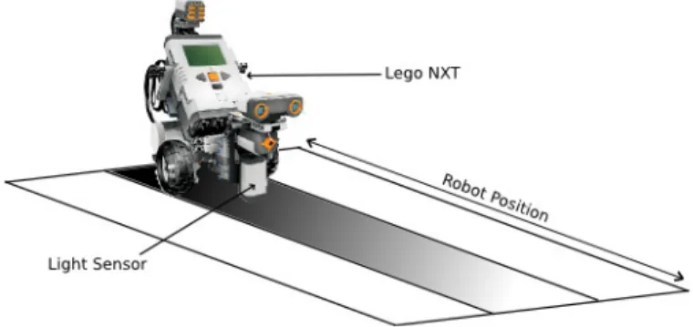
The considered robot is a mono-axis robot moving on an A3-size sheet of paper (see Fig. 1). On the sheet, a shaded lane from black (location 0) to white (location 100) is drawn. The robot owns two light sensors; the first one monitors the ground to assess the robot current location on the paper sheet and
the second one always monitors the white on the border lane to provide a reference independently of the room luminosity changes. The robot moves on the shaded lane mono-axis by using a servo motor. The control application is in charge of moving the robot to a desired location as quick as possible. The robot is connected via a USB cable to a Java Perc virtual machine3.
Fig. 1. The robotic demo example
A. A UML-MARTEmodel for the Robot
RT-Simex uses UML to represent the different views of a system. For that specific example, we use two composite structure diagrams, one for describing the application and another for describing the execution platform. TheUMLmodel is annotated with MARTE profile stereotypes. We mainly use three chapters of MARTE specification [14]. The Hardware Resource Modeling (HRM) part to describe the resources (de-vices, communication media, processing units, memories) and their properties; The Time chapter to identify the clocks and apply the constraints to build the reconciliation specification; Finally, the Allocation part is used to allocate the parts of the application onto the execution platform.
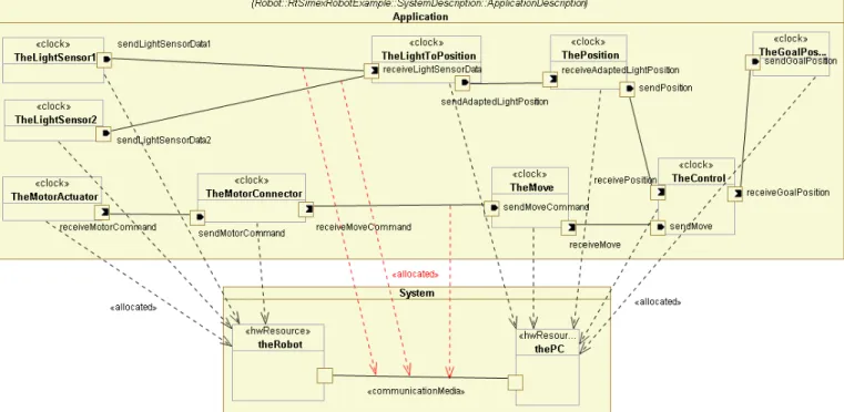
Figure 2 shows a simplified version of the UML/MARTE
model. The bottom part describes the execution platform made of the Robot and the external computer that controls the Robot. The two components are physically distant and communicate through a USB connection, a CommunicationMedia. Both parts are identified as being HwResources.
On the application part, the two light sensors send directly their raw information to the external computer. The computer uses that information to decide on the adequate movements to reach the goal position. These commands are sent back to the Robot, which interprets these commands through the part called TheMotorConnector and acts on the servo-motor. The four parts on the left side are physically performed by the Robot itself. We use MARTE allocation to denote this spatial distribution (dashed line). The other parts are actually performed on the external computer. Note also that some connectors are allocated to the system communication media to denote the cost of such a communication when appropriate. The reconciliation specification should impose constraints on when specific parts must be executed relative to each other.
Fig. 2. This composite diagram shows how the application parts are allocated to the Robot and PC
For instance, it should specify when the sensors (located on the Robot) operate relative to the controlling operation (located on the computer). Such a specification can be built inCCSLas long as the events involved are identified as Clocks. By tagging the part TheLightSensor1 with the stereotype «clock», the part becomes a clock and therefore the sensor operates when the clock ticks.
B. Time constraints with CCSL
CCSL is used to specify time constraints on the model elements. We give below some time constraints relevant for this example.
T heLightSensor1 = sendLightSensorData1 (1a) receiveM oveCommand 4 sendM oveCommand (1b) sendLightSensorData1+sendLightSensorData2 ≺
receiveLightSensorData (1c)
Equation 1a specifies that every time TheLightSensor1 operates, the value is sent through the port sendLightSen-sorData1and this is done instantaneously. The duration of the sensing action is neglected.
Equation 1b is the classical causality relation induced by a communication. The reception (receiveMoveCommand) always occur if an emission (sendMoveCommand) has oc-curred. It also states that there is no loss in the communication channel.
Equation 1c is a bit more complex since it uses the union operator (+). It states that every time one of the two sensors operates then, with possibly some delays, a data is received on port receiveLightSensorData. Note that, the two sensors cannot operate simultaneously, since they are located on the same unit (totally ordered).
V. PROPOSAL
Figure 3 gives an overview of our approach. The execu-tion of software over heterogeneous computaexecu-tional units is monitored by instrumenting the code. As a result, we obtain one OTF execution trace for each computational unit. Every trace defines a totally ordered set of event occurrences; the computational units are assumed to be sequential (with their own clock domain). Because the clock domains of the two computational units are likely to be unsynchronized, or based on different forms of time references (like in [19] for instance), it is a priori not possible to use the timestamps reported by the traces to sort the communication events. That is why there is a need for the execution trace reconciliation. Our approach goes in that direction. Each interaction between two units is considered as a causality relation and as such is used to order the events involved in this interaction; A send event precedes a receive event. Since some events are specific to one unit and not to an interaction, then the ordering is only partial. The reconciliation results in a partial order which is captured by our event occurrence relation model (see Section V-C and Section V-D). The reconciliation process is driven by a reconciliation specification extracted from UML
-MARTE models annotated with CCSL time constraints (see Section V-A). Because our approach is mainly model-based it is necessary to bring the OTF traces into the model technical space. Therefore, the OTF traces are transformed into trace models (see Section V-B).
The next subsections describe the approach in details. This paper studies a simplified scenario with only two traces. Nev-ertheless, our approach remains applicable to any number of traces. In this case, the approach is executed in an incremental
Fig. 3. Reconciliation of execution traces
fashion. For each iteration, the approach selects a pair of traces and its respective reconciliation specification, and uses the result of the reconciliation in the next iteration. At the end, we obtain a unique event occurrence relation model that contains the time and causal relationships for all the pairs of traces. A. Reconciliation specification
A reconciliation specification is a CCSL specification ex-tracted from a UML-MARTE model which has been annotated with time constraints. To extract only the temporal/causal relations of interest for the reconciliation, one must consider the set of constraints expressed on the connectors between ports whose instances are deployed on different computational units. These connectors express occurrences of a (real-time) communication event. For instance, in the running example Eq. (1c) and Eq. (1b) should be selected because they represent communications, which may be delayed, between the Perc JVM and the Robot brick. Even if the automatic extraction is not part of this paper, we believe that it can be automated for cases where the deployment is trivial (like in the running example). However, for more complex cases, user assistance may be necessary. In the remainder of the paper, we consider that the CCSL reconciliation specification is given.
B. Trace models
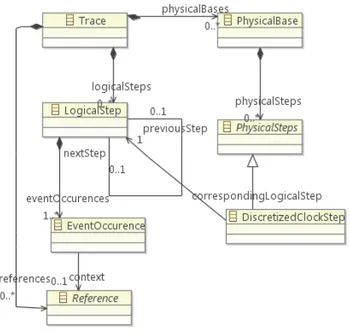
For each computational unit, there is a trace model which conforms to the metamodel depicted in Figure 4. The prin-cipal concepts are as follows. A Trace is a sequence of LogicalSteps. Each step contains several (simultaneous) EventOccurrences. A Reference associates an event occurrence with a clock or clock expression/relation estab-lished in the UML model. When all logical steps refer to a unique PhysicalBase of time (e.g.,, milliseconds), the trace is totally ordered.
In our approach, most of the event occurrences of a trace model come from an OTF execution trace, details about the translation process are out of the scope of this paper. However, some event occurrences are added afterwards to reflect the semantics of expression operators. For instance, to build the
Fig. 4. Simplified trace metamodel
union described in Eq. (1c), we need to extract from the trace, the specific occurrences of clocks sendLightSensor-Data1and sendLightSensorData2. To do that, we use FilteredByexpressions as illustrated in Figure 5. Trace1 is the trace model obtained from a robot execution. The different shapes correspond to occurrences of robot events, in particular, the triangles represent occurrences of sendLightSensor-Data1and sendLightSensorData2. The first FilteredBy expression selects instants of Trace1 that represent the event sendLightSensorData1, that is, the second and nineth occurrences. As indicated by the red arrows, the resulting instants coincide with the occurrences of Trace1.
Trace1 0 1 0 0 0 0 0 0 1 sendLightSensorData1 = Trace1 010000001 sendLightSensorData2 = Trace1 000010000 0 0 0 0 1 0 0 0 0 = Trace1 000010000 Coincides
Fig. 5. Extracting event occurrences from a trace model
C. Event occurrence relation model
This model defines temporal and causal relationships be-tween occurrences of trace models. The relationships indicate that, for some event occurrences in a specific trace model, there exist other occurrences (in another trace model), that precede (happen before) or coincide with (are simultaneous) the former occurrences. Unlike a reconciliation specification,
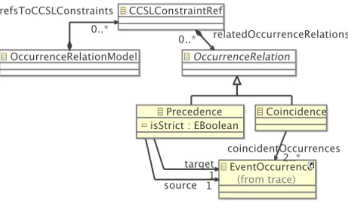
Fig. 6. The occurrence relation metamodel
that defines relationships between events (i.e., clocks), an occurrence relation model defines relationships between event occurrences (i.e., instants). An occurrence relation model along with a set of trace models represents a partial order. Occurrence relation models conform to a metamodel whose main concepts are displayed in Figure 6. The next paragraph explains the meaning of such concepts.
The root of the metamodel presented in Figure 6 is the entity OccurrenceRelationModel. It contains a set of CCSLCon-straintRef. This kind of elements references the clock con-straints of a CCSLspecification. It is just a way of sorting the OccurrenceRelationswith respect to the clock constraints that enforce them. An OccurrenceRelation is an abstract concept that represents the possible relationships between occurrences. It is materialized by two kinds of relations, the Precedence occurrence relation, which loosely synchronizes two event occurrences and the Coincidence event occurrence relation, which forces two event occurrences to be simultaneous. Note that when a Precedence is said to be non strict (isStrict boolean to false), it covers the union of the Precedence and Coincidence.
D. Reconciliation algorithm
This algorithm builds an occurrence relation model from a set of 3-tuples in an incremental way. For each 3-tuple hT race1, T race2, ReconSpeci, the algorithm calls the BP O method (listed in Alg. 1) that stands for “Build Partial Order”. The parameter occRelM odel of the BP O invocation is cumu-lative, i.e., every iteration may add new occurrence relations. The BP O method (listed in Alg. 1) proceeds as follows: it treats each constraint of a reconciliation specification sequen-tially. For each constraint, the first step is to test if it contains a clock expression or not (line 3). If not, the clocks referenced in the constraint must be in the traces and the reconciliation can be done (line 4). If the constraint contains a clock expression, it is necessary to run TimeSquare to apply the semantics of this expression to the traces. Rather than running a simulation for each expression, we form three different sets E, CE, and CST which (respectively) collect the expressions of all the constraints, the clocks referenced by the expressions (i.e., a set of FilteredBy expressions like the ones introduced
in Section V-B), and the constraints themselves (lines 6-10). Once all the constraints without expressions have been treated and the three previous sets have been constructed,TimeSquare is called using as parameter aCCSLspecification that contains the union of the FilteredBys (CE) and the expressions (E). CCSL simulates the specification and gives as a result a new trace and an occurrence relation model (line 13). This model referred to ExprOccRelM odel contains occurrence relations deduced from the expressions. Next the algorithm establishes coincidence relationships between the occurrences of the clock expression (contained in ExprOccRelM odel) and the occurrences of other clocks in the original traces (line 14). At this step, all the occurrences resulting from clock expressions are available, therefore it is possible to create the occurrence relations (line 15). The type of the relations depends on the constraint semantic (see Section III). For instance, for a precedence constraint between a and b, ∀k ∈ N+\ {0}, the method creates precedence occurrence
relations between a[k] and b[k]. Algorithm 1 The BPO method
1: BPO(Trace1, Trace2, ReconSpec, occRelModel)
2: for all constraint ∈ ReconSpec do
3: if @expression ∈ constraint then
4: occRelM odel ← CreateOccRelations(T race1, T race2, constraint, occRelM odel)
5: else
6: CST ← CST.append(constraint)
7: for all expression ∈ constraint do
8: CE ← CE.append(GetClockF ilteredBy(T race1,
T race2, expression))
9: E ← E.append(expression) 10: end for
11: end if
12: end for
13: hExprT race, ExpOccRelM odeli ←
GetN ewT race((CE ∪ E))
14: occRelM odel ← AddCoincidences(T race1, T race2 ReconSpec, occRelM odel, ExpOccRelM odel)
15: for all constraint ∈ CST do
16: occRelM odel ← CreateOccRelations(T race1, T race2, constraint, occRelM odel)
17: end for
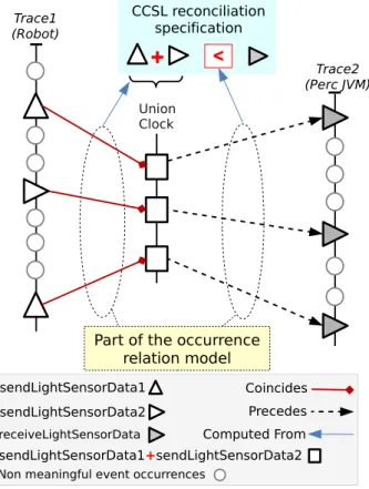
Let us now show the algorithm in action. To do so, we take a reconciliation specification with one constraint (the one stated in Eq. (1c)) and the trace models obtained from the execution of robot and Perc JVM. The key points of the process are graphically illustrated in Figure 7. As indicated by the legend, the different shapes represent occurrences of clocks (i.e., events) and the arrows temporal relationships between them. Below we describe how the algorithm derives such relationships.
Trace2 (Perc JVM)
receiveLightSensorData
Precedes Computed From
Part of the occurrence relation model Coincides sendLightSensorData1 Trace1 (Robot) sendLightSensorData2
+
<
CCSL reconciliation specification Union Clock sendLightSensorData1+sendLightSensorData2Non meaningful event occurrences
Fig. 7. Overview of the reconciliation algorithm applied to the running example
sendLightSensorData1 + sendLightSensorData2, the algorithm has to build a CCSL specification which is composed of the equations 2a, 2b, and 2c. The two first equations are FilteredBys (representing the clocks sendLightSensorData1 and sendLightSensorData2 sep-arately) and the third one is the union expression itself. The algorithm runsTimeSquare using as a parameter such aCCSL
specification, it gives as a result a new trace model and an occurrence relation model. The new trace model contains the occurrences of the union expression which have to be copied into T race1. The occurrence model relation, in turn, indicates that Coincides relations have to be established between the occurrences of the union expression and the occurrences of sendLightSensorData1 and sendLightSensorData2 re-ported in T race1 (as shown by the red arrows). Finally, Precedes relations that satisfy the constraint are created, the result is depicted by the dotted black arrows. Both Coincides and Precedes relations are captured in the occurrence relation model.
sendLightSensorData1 = T race1H010000001; (2a) sendLightSensorData2 = T race1H000010000; (2b) union = sendLightSensorData1+sendLightSensorData2 (2c)
E. Proof of concept
We have developed a prototype on top of Java,TimeSquare4,
and ATL5. A Java program translates OTF traces [11] into
models conforming to the trace metamodel. When a recon-ciliation specification contains clock expression constraints,
4http://www.inria.fr/sophia/aoste/dev/time square 5http://www.eclipse.org/atl/
TimeSquare is called to simulate its corresponding new spec-ification. Remember that the new specification consists of FilteredBy expressions plus the initial constraints. The rec-onciliation algorithm is a Java program that, for each 3-tuple hT race1, T race2, ReconSpeci, calls the BP O method implemented as an ATL transformation. The prototype has been applied to the running example, it takes as an input a pair of OTF traces of 54KB and a reconciliation specification containing a simple precedence relationship. As an output, we have obtained trace models of 74KB and an event occurrence relation model of 22KB. Looking at these results shows that trace models are almost 40% more verbose than the initial OTF traces. However, this translation is needed for being in the same technical space that UML-MARTE models which are (as well as the code) the artifacts subject to debugging and verification. An advantage is the availability of tools to navigate, transform, and visualize such models.
VI. APPROACH APPLICABILITY AND LIMITATIONS
Our approach proposes a way to construct, offline, the partial order that represents the execution of a distributed real-time system. In this section we discuss the approach limitations and the benefits provided by our partial order which is model-based.
a) Limitations: We have seen that sometimes, it is nec-essary to reconstruct some events (clocks) that are referenced by the reconciliation specification but that do not exist in the traces (lines 6-10 of Alg. 1 are devoted to this). In our example, it is the case for the union clock (sendLightSensor-Data1+ sendLightSensorData2). This union consists of adding some Coincides occurrence relations between the two clocks referenced by the expression and the union clock itself. These relations indicate a partial order iff the two clocks referenced by the expression are totally ordered (otherwise an arbitrary order is chosen by TimeSquare). However, the two clocks might be unsynchronized if they are allocated to dif-ferent computational units. As a consequence, it is impossible to make a meaningful reconciliation. In this case, one needs to enrich the scenario with information at model or code level before the reconciliation. At model level, it is necessary to define a static constraint to ensure that each communication is on a dedicated port (i.e.,receiveLightSensorData1 and receiveLightSensorData2). By doing so, there is no need for a union expression in the reconciliation. Other so-lution is to emulate the previous situation in the instrumented code where a different event is monitored depending on the sender of a message to the port receiveLightSensor-Data.
b) Approach applicability: The resulting partial order is adequate for classical analysis already conducted in previous works [2], [3], [4], [5], [6]. In addition, because our approach is fully integrated in an MDE workflow, many benefits, de-scribed in the following paragraphs, are provided.
Because the events identified in the execution traces are specified in the UML/MARTE model, the partial order is actually linked to the model elements and can be used to
give feedback from the real execution directly at the model level. For instance, it is possible to animate a UML diagram according to the system execution. For example, the developer may be able to run a “partial-order based” debugger to pinpoint any problem of ordering between the messages of a sequence diagram. This work is currently under realization in the RT-Simex project.
Another way to help debugging would consists in creating a consolidated timing diagram. That is, instead of visualizing several timing diagrams representing the totally ordered behav-ior of a single computational units in an isolated way, a partial order can be used to represent a timing diagram of the whole system. This timing diagram would contain the occurrences of events belonging to each computational unit, including the occurrences of communication events, and the causal and temporal relationships between occurrences. From the timing diagram one can perceive the ordering and scheduling of event occurrences as well as the dependencies between them. This view can be helpful in the first steps of the debugging but some problems can be difficult to detect visually. In this case we can decide to use an exhaustive verification technique.
In [20] we have described a verification strategy based on the TimeSquare tool. It consists of building aCCSL specifica-tion that represents the execuspecifica-tion of the partial order. Then, the original constraints specified on the model are marked as assertions. TimeSquare takes such a CCSL specification and checks if some assertions are violated. In case of violations, the constraint and the step where the violation has occurred are provided. For each violation, an event is raised so that it is possible to launch specific feedback on assertions (for instance meaningful annotation of the model).
VII. CONCLUSION
In many real-time systems, different computational units communicate to deliver a functionality. To understand such systems, it is common to produce execution traces. These traces are traditionally produced by using a synchronization between computational units clocks. To avoid the overhead due to such a synchronization, we propose an approach that reconciles the traces from different computational units offline, after the execution. It therefore provides a partial order repre-senting the distributed execution. To build the partial order, our approach needs two inputs: 1) traces that result from the exe-cution of instrumented code over all the computational units, and 2) a reconciliation specification, i.e., theCCSLconstraints that represent the temporal and causal relations induced by the communications between the computational units. Apart from the execution traces, which are captured in the OTF format for performance reasons, all the approach is based on MDE techniques. Moreover, it uses the formal language CCSLas a reconciliation specification language which would ease further phases of analysis. The approach has been successfully tested on a case study addressed during the ANR project RT-Simex.
As future work, two directions appear: using the partial order to visualize real execution on the model and analyzing the partial order to extract information about possible deadlock schemes on the communications. The latter part would consist in using the unfolding of clock relations into instant relations to detect causality cycles.
VIII. ACKNOWLEDGMENTS
This work has been funded by the ANR RT-Simex project. REFERENCES
[1] A. Pietschker and A. Ulrich, “A light-weight method for trace analysis to support fault diagnosis in concurrent systems,” Systemics, cybernetics and informatics, vol. 1, 2003.
[2] C. Fidge, “Logical time in distributed computing systems,” Computer, vol. 24, pp. 28–33, August 1991.
[3] M. Raynal and M. Singhal, “Logical time: Capturing causality in distributed systems,” Computer, vol. 29, pp. 49–56, February 1996. [4] L. Lamport, “Time, clocks, and the ordering of events in a distributed
system,” Commun. ACM, vol. 21, pp. 558–565, July 1978.
[5] J. Moe and D. A. Carr, “Understanding distributed systems via execution trace data,” in 9th International Workshop on Program Comprehension. Society Press, 2001, pp. 60–67.
[6] A. Pietschker and A. Ulrich, “A light-weight method for trace analysis to support fault diagnosis in concurrent systems,” Journal of Systemics, Cybernetics and Informatics, vol. 1, no. 6, pp. 1–6, 2003.
[7] I. Bate, P. Nightingale, and A. Cervin, “Establishing timing requirements and control attributes for control loops in real-time systems,” in ECRTS. IEEE Computer Society, 2003, pp. 121–128.
[8] C. Andr´e, “Syntax and semantics of the Clock Constraint Specification Language,” INRIA, Tech. Rep. 6925, 2009.
[9] S. K. Sarin and N. A. Lynch, “Discarding obsolete information in a replicated database system,” IEEE Trans. Software Eng., vol. 13, no. 1, pp. 39–47, 1987.
[10] F. Ruget, “Cheaper matrix clocks,” in Proc. of the 8th Int. W. on Distributed Algorithms, ser. WDAG ’94. London, UK: Springer, 1994, pp. 355–369.
[11] A. Knupfer, R. Brendel, H. Brunst, H. Mix, and W. Nagel, “Introducing the Open Trace Format (OTF),” in Computational Science (ICCS), ser. Lecture Notes in Computer Science.
[12] H. Barringer, A. Groce, K. Havelund, and M. Smith, “Formal analysis of log files,” Journal of aerospace computing, information, and commu-nication, vol. 7, no. 11, pp. 365–390, 2010.
[13] R. Gascon, F. Mallet, and J. DeAntoni, “Logical time and temporal logics: comparing UML MARTE/CCSL and PSL,” in 18th Int. Symp. on Temporal Representation and Reasoning (TIME), 2011, to appear. [14] OMG, UML Profile for MARTE, v1.0, Object Management Group,
November 2009, formal/2009-11-02.
[15] C. Andr´e, F. Mallet, and R. de Simone, “Modeling time(s),” in MoDELS, ser. Lecture Notes in Computer Science, G. Engels, B. Opdyke, D. C. Schmidt, and F. Weil, Eds., vol. 4735. Springer, 2007, pp. 559–573. [16] OMG, UML Superstructure, v2.2, Object Management Group, February
2009, formal/2009-02-02.
[17] J. DeAntoni, F. Mallet, and C. Andr´e, “TimeSquare: on the formal execution of UML and DSL models,” Tool session of the 4th Model driven development for distributed real time systems, 2008.
[18] Lego Systems, “mindstorms NXT,” http://mindstorms.lego.com/eng/Overview/The NXT.aspx.
[19] M.-A. Peraldi-Frati and J. DeAntoni, “Scheduling multi clock real time systems: From requirements to implementation,” in 14th IEEE Int. Symp. on Object/Component/Service-oriented Real-time Distributed Computing, 2011, pp. 50–57.
[20] J. DeAntoni, F. Mallet, F. Thomas, G. Reydet, J.-P. Babau, C. Mraidha, L. Gauthier, L. Rioux, and N. Sordon, “RT-Simex: retro-analysis of exe-cution traces,” in 18th Symp. on the Foundation of Software Engineering (FSE), 2010.