HAL Id: hal-01476485
https://hal.archives-ouvertes.fr/hal-01476485
Submitted on 24 Feb 2017
HAL is a multi-disciplinary open access
archive for the deposit and dissemination of
sci-entific research documents, whether they are
pub-lished or not. The documents may come from
teaching and research institutions in France or
abroad, or from public or private research centers.
L’archive ouverte pluridisciplinaire HAL, est
destinée au dépôt et à la diffusion de documents
scientifiques de niveau recherche, publiés ou non,
émanant des établissements d’enseignement et de
recherche français ou étrangers, des laboratoires
publics ou privés.
Efficient diode laser line narrowing using dual,
feed-forward + feed-back laser frequency control
Michel Lintz, Duy-Ha Phung, Jean-Pierre Coulon, Benoit Faure, Thomas
Lévèque
To cite this version:
Michel Lintz, Duy-Ha Phung, Jean-Pierre Coulon, Benoit Faure, Thomas Lévèque. Efficient diode
laser line narrowing using dual, feed-forward + feed-back laser frequency control. Review of Scientific
Instruments, American Institute of Physics, 2017, 88 (2), pp.26102 - 26102. �10.1063/1.4975400�.
�hal-01476485�
NOTE: Efficient diode laser line narrowing using dual, forward +
feed-back laser frequency control
M. Lintz,
1,a)D. H. Phung
1,b), J.-P. Coulon
1, B. Faure
2and T. Lévèque
21Laboratoire ARTEMIS, Universite Cote d'Azur, Observatoire de la Cote d'Azur, CNRS, Nice 06304, France 2Centre National d'Etudes Spatiales, 18 rue Edouard Belin, Toulouse 31401, France
(Received XXXXX; accepted XXXXX; published online XXXXX)
We have achieved DFB laser diode line narrowing by simultaneously acting on the diode current via a feed-back loop and on an external electrooptic phase modulator in feed-forward actuator. This configuration turns out to be very efficient in reaching large bandwidth in the phase correction: up to 15 MHz with commercial laser control units. About 98% of the laser power undergoes narrowing. The full width at half maximum of the narrowed optical spectrum is of less than 4 kHz. This configuration appears to be very convenient as the delay in the feed-forward control electronics is easily compensated for by a 20 m optical fiber roll.
Distributed feedback (DFB) diode lasers are convenient, compact, robust single mode laser sources and are used in many areas of science. Their emission linewidth, in the MHz to several MHz range, may be too large for some applications, such as cold atom physics, lidar or gas sensing. In principle, narrowing the optical spectrum can be achieved by controlling the diode current to lock the laser diode frequency against a frequency discriminator (optical interferometer or atomic or mole-cular line). Efficient line narrowing requires to control the laser frequency in the 10 MHz range. However, a feedback loop with such a large bandwidth is difficult to obtain, not only due to delays in the loop (propagation, electronics) but also because of the complex response of the laser frequency to a current change. The latter is dominated at low Fourier frequency by the temperature change of the active medium, and at high Fourier frequency by the physics of the carriers. The crossover takes place at about 1 MHz, and complicates feedback (FB) loops with MHz bandwidth. In the closely related domain of optical phase locked loops, miniaturized setups1 and photonic integrated
circuits2 have succeeded in reaching lock bandwidths of
one or several hundred MHz, respectively, using lasers with sections devoted to fast modulation.
"Feed-forward" (FF) correction control provides a relevant alternative. Although it has not been frequently used, it allowed "optical phase cloning" of a CW narrow linewidth laser to a DFB laser3 using a single-sideband
modulator. It was used also for the locking of a DFB diode laser to a frequency comb4. The setup uses an
acousto-optic frequency shifter (AOFS) as the feed-forward optical frequency actuator.5,6 The same approach can be
implemented for locking to a frequency discriminator, at the expense of a relatively complex set-up. But the bandwidth of the feed forward is limited, to below 1 MHz,
(a)Electronic mail: [email protected]
(b)Now at laboratoire Geoazur, 06560 Sophia-Antipolis, France
by the time delay inherent to the AOFS. In ref.7 a
wideband (≈50 MHz) laser phase noise reduction was achieved in an all-fibre setup. However the single-sideband modulator adds some complexity7 and induces
significant losses to the narrowed laser output.
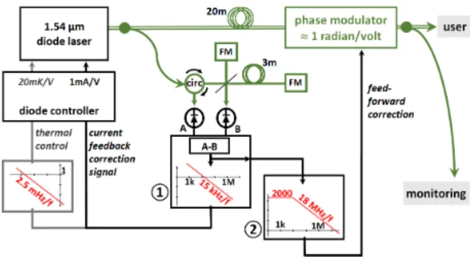
We find that the "dual", feed-forward + feedback setup sketched in Fig. 1 can be implemented with standard, off the shelf, inexpensive commercial fibre components from the telecom industry, and commercial servo units (hereunder we use the term "servo" units, even though this term is inappropriate for the feed-forward arm of the line narrowing setup). In addition to a 100 kHz bandwidth feedback to the laser diode current, we use an external, large bandwidth electrooptic phase modulator in feed-forward configuration, and reach high efficiency line narrowing.
The DFB laser diode (model 1905 LMI from 3S Photonics) includes a Peltier cooler for thermal control and
FIG. 1. Set-up for spectral narrowing of the DFB diode laser. Green lines: single mode optical fibre. Double green line: polarization maintaining optical fibre. FM: Faraday mirror. 20m, 3m: fiber spools. circ: fibred optical circulator. ①, ②, electronic gain units for feedback and feed-forward actuation, respectively. The transfer functions are given in red, with expressions where the Fourier frequency, f, is in Hz. "monitoring": see the spectral characterization set-up shown in Fig. 5.
FIG. 2. Beat-note signal power spectrum (10 dB/div), with (red lines) or without (blue dots) feed-forward correction. Inset: central (30 kHz) part of the beat-note spectrum, in linear units (RBW 3 kHz, sweep time 0.2 s). Laser diode current: 125 mA.
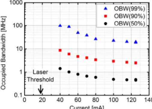
FIG. 3. "Occupied bandwidth" of the free-running DFB laser spectrum (at 50%, 90% and 99% of the optical power), vs diode laser current.
an optical isolator. To characterize the optical spectrum of the laser system we form the beat-note with a fiber laser which features a ≈kHz linewidth, and serves as a reference. The beat-note spectra (Fig. 2) are recorded by a spectrum analyzer. In free-running operation, they manifest the increase of the spectral broadening of the emission as the current is lowered towards the DFB diode laser threshold. This can be conveniently illustrated by the "occupied bandwidth at P%", i.e. the central optical bandwidth that contains P% of the total optical power. The occupied bandwidth (OBW) at 50% slightly degrades from 0.47 to 0.6 MHz when the current is lowered from 125 to 80 mA (Fig. 3.)
The current driver is a Vescent Photonics D2-105 controller. Its current noise, specified at 100 pA/√Hz, is low enough not to give any significant contribution to the laser diode frequency noise. A servo input allows for addition, to the DC current output, of a correction with a gain of 1 mA/V in a 10 MHz bandwidth. The unit also provides the thermal regulation of the diode. This function is used (grey lines in Fig. 1) to prevent the current correction voltage from increasing over long periods of time, but is not the subject of this Note.
The optical frequency discriminator uses an all-fiber Michelson interferometer with a ∆L
=
3 m length imbalance (Fig. 1), Faraday mirrors as reflectors, and two photodiodes. Photodiode A (B) provides a signal) / 2 2 cos( ) (
1+ − πnν× ∆L c , with c the speed of light,
n
the optical fiber index and ν the optical frequency. The difference between the two photodiode signals provides an error signal S∝2cos(2πnν×2∆L/c) for the FB and FF loops with, around zero, a slope dS/dν= 50 mV/MHz.Two "servo" electronics are required to generate the correction signals:
- an integrator to provide the feedback correction to the diode laser current driver (① in Fig. 1), with a lock bandwidth of ≈100 kHz,
- an electronics for the feed-forward to the electrooptic phase modulator (②in Fig. 1). As the error signal is a frequency error signal, generating the phase correction signal also requires an integrator. But this integrator has to provide correction signals only at high frequencies, 100 kHz and above.
We use two Newport LB1005 servo units. The differential input rejects possible intensity noise in the DFB laser. The "Low Frequency Gain Limit" option helps to prevent feeding the electrooptic modulator with large DC signals that could result from offsets. The LB1005 servo units provide an integrator (1/f) transfer function only up to a corner frequency of 1 MHz, above which the response is flat. For the feed-forward arm, we need a pure integrator in the MHz domain. Therefore, servo ② is fitted with a passive, appropriately designed RC filter (not show in Fig. 1) to obtain the required, pure integrator transfer function. The phase modulator is a Photline MPX-LN-0.1, PM fiber-pigtailed, LiNbO3 modulator with a flat,
≈1 radian/volt response over a 100 MHz bandwidth. The spectrum of the beat-note signal is quite similar when engaging, or not, the feed-back correction to the current driver: the 100 kHz feed-back bandwith is not large enough to give rise to efficient narrowing. When the feed-forward correction is active, with the appropriate gain, the spectrum of the DFB laser is affected up to a ≈ 15 MHz bandwidth. In the conditions of Fig. 2, the sharp peak (measured in a ±150 kHz interval) contains about 99% of the total optical power. Note that this value requires that a fiber roll of about 20 m be inserted before the phase modulator to compensate for the delay in the servo electronics. With a fiber roll of 17 m, the narrowing efficiency drops to 97%. The delay issue is much easier to deal with in the feed-forward configuration than in the feed-back configuration, in which delay can only reduce the lock bandwidth.
The fraction of narrowband optical power also degrades when the operating current of the DFB laser is lowered, and drops below 99% (Fig. 4). This is expected from the measured occupied bandwidth @99% in free-running operation (Fig. 3): OBW@99% increases from 19 MHz at 125 mA to 26 MHz at 80 mA, already exceeding the ≈15 MHz bandwidth of the FF correction.
FIG. 4. Fraction of narrow-band optical power when the feed-forward correction is activated, as a function of the DFB diode laser current. The gain of the FF correction is re-adjusted for each value of the current.
The full width at half maximum of the optical spectrum has been repeatedly found below 4 kHz (Fig. 2, inset). Accurate values are difficult to give as our reference laser is neither infinitely narrow, nor ideally stable.
FIG. 5. Characterization setup: beat-note recording, and measurement of the RMS frequency noise. 100m: long arm fiber roll for the monitoring interferometer. Pz: piezo-actuated fibre stretcher.
We found that the optimal condition remains stable: the feed-forward gain
FF
G does not need to be readjusted every day. However it has to be readjusted as soon as the diode laser is operated at a different current. Adjusting the FF gain (or the delay fibre spool length) to achieve the subtraction 1−GFF =0 to a high degree of rejection, may
be difficult if a reference laser is not available to monitor the resulting narrowing efficiency. To help the operator in
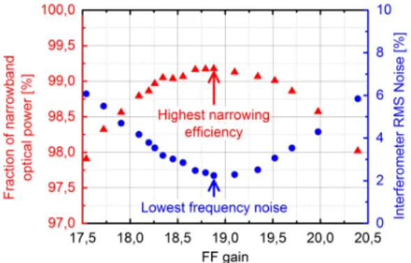
FIG. 6. Residual fraction of broadband optical power and fractionnal RMS noise of the monitoring interferometer signal vs amplitude gain on the FF correction unit.
finding the optimal FF conditions we implemented a second, "monitor", Michelson interferometer. Compared to the frequency discriminator used to generate the frequency error signal (Fig. 1), the monitor interferometer has a much larger (100 m) arm length difference, and includes a path length modulator (Optiphase PZ1-SMF fibered stretcher), Fig. 5. We modulate the fiber length with a depth of 2.5 optical wavelengths, at about 12 Hz. Thus we scan 5 fringes of the monitor interferometer signal. When the FF correction is not active, the frequency noise is large enough that the signal of this monitor interferometer spreads over the whole signal range interval, showing no fringe structure. When the FF correction is active, the noise on the monitor signal is considerably lowered, so that the five fringes associated to modulation by the fibre stretcher appear. Yet, the frequency noise of the narrowed laser source is observable (blue trace in Fig. 5). We measure the RMS noise of the signal at the output of a high pass filter (red trace). As shown in Fig. 6, this provides a convenient way to optimize the narrowing efficiency, as the optimal line narrowing matches the lowest RMS frequency noise.
The method used here to achieve high-efficiency spectral narrowing of a DFB diode laser appears particularly convenient. The setup uses commercial servo units and inexpensive fibre components and requires no particular design (apart from path length equalization). We characterize the spectrally-narrowed laser source by beating the beam with a reference laser. The power in the ± 150 kHz interval is about 99% of the total laser power (96% in a ± 40 kHz interval). By contrast, the usual approach of the nested feed-back (to the laser diode current and to the phase modulator) has provided narrowing efficiencies of 80 to 85% at best. The full width at half maximum is below 4 kHz. It can be used at any wavelength provided polarization maintaining fibres and gold-coated fibre mirrors are used whenever Faraday mirrors are not available.
We acknowledge financial support from CNES (Centre National d'Etudes Spatiales). We thank F. Kéfélian, M. Daldosso, M. Merzougui and Y. Barje for help in the simulations and in the experiments.
1 U. Gliese, T. N. Nielsen, M. Bruun, E. Lintz Christenson, K. Stubkjaer,
S. Lindgren, and B. Broberg, IEEE Phot. Technol. Lett. 4, 936 (1992).
2 M. Lu, H. Park, E. Bloch, A. Sivananthan, A. Bardwaj, Z. Griffith, L. A.
Johansson, M. J. Rodwell and L A. Coldren, Opt. Expr 20, 9736 (2012).
3 J. Burkart, T. Sala, S. Kassi, D. Romanini and M. Marangoni, Opt. Lett. 40 816 (2015).
4 D. Gatti, T. Sala, A. Gambetta, N. Coluccelli, G. Nunzi Conti, G.
Galzerano, P. Laporta, and M. Marangoni, Opt. Express 20, 24880 (2012).
5 S. Koke, C. Grebing, H. Frei, A. Anderson, A. Assion and G.
Steinmeyer, Nat. Photonics 4, 462 (2010).
6 K. Lücking, A. Assion, A. Apolonski, F. Krausz and G. Steinmeyer,
Opt. Lett. 37, 2076 (2012).