HAL Id: hal-02138494
https://hal.archives-ouvertes.fr/hal-02138494
Submitted on 23 May 2019
HAL is a multi-disciplinary open access
archive for the deposit and dissemination of
sci-entific research documents, whether they are
pub-lished or not. The documents may come from
teaching and research institutions in France or
abroad, or from public or private research centers.
L’archive ouverte pluridisciplinaire HAL, est
destinée au dépôt et à la diffusion de documents
scientifiques de niveau recherche, publiés ou non,
émanant des établissements d’enseignement et de
recherche français ou étrangers, des laboratoires
publics ou privés.
A Scenario-Based Approach for Checking Consistency in
User Interface Design Artifacts
Thiago Rocha Silva, Marco Winckler
To cite this version:
Thiago Rocha Silva, Marco Winckler. A Scenario-Based Approach for Checking Consistency in User
Interface Design Artifacts. XVI Brazilian Symposium on Human Factors in Computing Systems, Oct
2017, Joinville, Brazil. pp.3, �10.1145/3160504.3160506�. �hal-02138494�
A Scenario-Based Approach for Checking Consistency in
User Interface Design Artifacts
Thiago Rocha Silva
ICS-IRIT, Université Paul Sabatier
Toulouse, France
[email protected]
Marco Winckler
ICS-IRIT, Université Paul Sabatier
Toulouse, France
[email protected]
ABSTRACT
Keeping the consistency of requirements in different artifacts along the development process is a cumbersome activity, especially if it is done manually. Previous studies have investigated the use of User Stories to write testable requirements in order to automate the assessment of a given set of development artifacts. This paper expands the research in this field describing a scenario-based approach for checking consistency in User Interface (UI) design artifacts, modeling business and user requirements. A case study is presented as a proof of concept showing how our approach could be used to ensure the consistency of both business and task models, besides UI prototypes and scenarios. Preliminary testing results have shown that our approach is able to identify even fine-grained inconsistencies in the mentioned artifacts, allowing establishing a reliable compatibility among different UI design artifacts.
Author Keywords
Scenario-Based Design, User Interface Design Artifacts, Automated Assessment, User Stories, Business Modeling, Task Modeling, Prototyping.
ACM Classification Keywords
H.5.2. Information interfaces and presentation (e.g., HCI): User Interfaces.
INTRODUCTION
Modeling information systems is a very complex task. Several aspects of information, from the macro business goals until the most detailed information about user tasks must be taken into account. For facing this challenge, software systems tend to be designed based in several requirements artifacts, modeling different aspects of the system (e.g. business models, use cases, task models, etc.). Artifacts are the means by which the outcomes of these modeling activities are registered. As many stakeholders have different views of the system and different phases of development require distinct information, artifacts used for modeling tend to be very diverse throughout the development and ensuring their consistency is quite
challenging [25]. In iterative processes, the cycle of producing and evaluating artifacts permeates all phases of system development, from requirements and business analysis until the software testing.
On one hand, business requirements are usually modeled using Business Process Modeling Notation (BPMN) [8]. BPMN is a well-established approach to model business-oriented tasks in a high-level of abstraction through a workflow view. User requirements, on the other hand, can be obtained using a diverse set of methods. User-centered approaches usually model requirements using artifacts such as scenarios, task models and prototypes. In a scenario-based approach, these artifacts can be additionally aligned to pro-vide a complete software design specification for interactive systems.
User Stories [4] are artifacts that allow specifying natural language requirements using scenarios in a simple and understandable way for different stakeholders. Additionally, scenarios from User Stories can be directly tested from their textual specifications. They provide actually a “live” documentation once it contains, in a single artifact, the specification itself besides test cases which are able to certify whether some requirement has been attended or not. However, current testing approaches using User Stories focus essentially on assessing final user interfaces that are typically produced late in the development process.
Since long time ago, it is a peaceful argument that providing early assessment is very helpful for detecting errors of modeling as soon as possible, before making strong commitments with the software implementation [14]. Nonetheless, ensuring the consistency of other artifacts every time a requirement is introduced and/or modified is a discouraging activity for software development teams, especially if it should be done manually. Several tools both in the academy and industry environments have provided means of vertically tracing requirements through different artifacts, although they do not provide means of checking the consistency of such requirements [23].
In this paper, we propose to explore the use of such techniques to investigate testing perspectives for user interface design artifacts that model different aspects of both business and user requirements. Considering a scenario-based approach, the aim is to verify and test the consistency of three early artifacts: BPMN models, low-fidelity prototypes and task models, looking for errors and
Permission to make digital or hard copies of all or part of this work for personal or classroom use is granted without fee provided that copies are not made or distributed for profit or commercial advantage and that copies bear this notice and the full citation on the first page. Copyrights for components of this work owned by others than ACM must be honored. Abstracting with credit is permitted. To copy otherwise, or republish, to post on servers or to redistribute to lists, requires prior specific permission and/or a fee. Request permissions from [email protected].
IHC 2017, October 23–27, 2017, Joinville, Brazil © 2017 Association for Computing Machinery. ACM ISBN 978-1-4503-6377-8/17/10…$15.00 https://doi.org/10.1145/3160504.3160506
inconsistencies when modeling functional requirements. A case study for the flight tickets e-commerce domain is presented as a proof of concept to attest the feasibility of the approach. In the following sections, we present the foundations for our approach, followed by our strategy for modeling and conducting tests in the mentioned artifacts. Further, we describe a case study that demonstrates its feasibility and discuss the advantages and shortcomings of the approach. Lastly, we lay out our next steps for research in this field.
FOUNDATIONS
User Stories and Scenario-based design
Scenario-based design (SBD) is a family of techniques in which the use of a future system is concretely described at an early point in the development process. Narrative descriptions of envisioned usage episodes are then employed in a variety of ways to guide the development of the system. Like other user-centered approaches, scenario-based design changes the focus of design work from defining system operations (i.e., functional specification) to describing how people will use a system to accomplish work tasks and other activities [19].
SBD follows an iterative design framework in which scenarios serves as a central representation of requirements throughout the development cycle, first describing the goals and concerns of current use, and then being successively transformed and refined through an iterative design and evaluation process (Figure 1). However, from analysis to evaluation, the SBD cycle does not tackle how to manage and assess the flow of artifacts that are produced all along these multiple development phases.
Figure 1. An overview of the scenario-based design (SBD) framework (from Rosson & Carroll [19]).
As central representation of requirements, scenarios can admit multiple templates according to the phase of development and to the level of abstraction that they are addressing for some information. Free narratives, for example, are useful in the very early phases, when typically high-level business requirements are being defined (problem scenarios). Nevertheless, they are a frequent source of
misunderstandings when used to refine requirements in activity or interaction scenarios in the design phase. Semi-formatted templates like in User Stories are better suitable in this case.
The use of User Stories for modeling requirements has been proposed by Cohn [4]. The author suggests formalize these stories in an artifact describing a feature and its acceptance criteria, with concrete examples about what should be tested to consider this feature as “done”. Below it is presented a template proposed by North [15] and Cohn [4]:
Title (one line describing the story) Narrative:
As a [role] I want [feature] So that [benefit]
Acceptance Criteria: (presented as Scenarios) Scenario 1: Title
Given [context]
And [some more context]... When [event]
Then [outcome]
And [another outcome]... Scenario 2: ...
According to this template, a User Story is described with a title, a narrative and a set of scenarios representing the acceptance criteria. The title provides a general description of the story, referring to a feature that this story represents. The narrative describes the referred feature in terms of the role that will benefit from the feature, the feature itself, and the benefit it will bring to the business. The acceptance criteria are defined through a set of scenarios, each one with a title and three main clauses: “Given” to provide the context in which the scenario will be actioned, “When” to describe events that will trigger the scenario and “Then” to present outcomes that might be checked to verify the proper behavior of the system. Each one of these clauses can include an “And” statement to provide multiple contexts, events and/or outcomes. Each statement in this representation is called step.
User Stories are usually specified by Product Owners [20] to settle a big picture about features that will be developed, emphasizing, for each one, the business value they will bring to users. The set of acceptance criteria that compose the User Story determines whether a feature can be considered as “done”, i.e. under which conditions stakeholders will consider this feature able to add value to the business. By specifying such conditions through examples of use, stakeholders set up the validation scenarios under which the system should be tested.
Business Process Modeling
Business Process can be understood as the step-by-step rules specific to the resolution of some business problem. Business Process Modeling (BPM) refers to the design and execution of business processes. Among the benefits of BPM are the formalization of current processes and the support for efficiently automating the process flow. Business Process
Modeling Notation (BPMN) is a graphical flowchart-like language intended for use by business analysts and developers to build business process diagrams [9].
Notational elements in business process diagrams are di-vided into four basic categories: flow objects, artifacts, connecting objects and swimlanes, each of which consists of a set of elements. They include events, activities, gateways, data objects, groups, annotations, sequence and message flows, and associations. By following the flow of activities in the model, we succeed building high-level scenarios. Examples of notational elements are presented in the case study.
Modeling User Requirements for Interactive Systems
Task Modeling
Task models provide a goal-oriented description of interactive systems, but avoiding the need for the level of detail required for a full description of the user interface. Each task can be specified at various abstraction levels, describing an activity that has to be carried out to fulfil the user's goals. By modeling tasks, designers are able to describe activities in a fine granularity, for example, covering the temporal sequence of tasks to be carried out by the user or system, as well as any preconditions for each task [16].
HAMSTERS [13] is a tool-supported graphical task modeling notation for representing human activities in a hierarchical and ordered manner. At the higher abstraction level, goals can be decomposed into sub-goals, which can in turn be decomposed into activities. The output of this decomposition is a graphical tree of nodes. Nodes can be tasks or temporal operators. Tasks can be of several types and contain information such as a name, information details, and criticality level. Abstract Task is a task that involves sub-tasks of different types. System Task is a task performed only by the system. User Task is a generic task describing a user activity. It can be specialized as a Motor Task (e.g. a physical activity), a Cognitive Task (e.g. decision making, analysis), or Perceptive Task (e.g. perception of alert). Finally, Interactive Task represents an interaction between the User and the System; it can be refined into Input Task when the users provide input to the system, Output Task when the system provides an output to the user, and Input/Output Task that is a mix of both, but performed in an atomic way. Additionally, temporal relationships between tasks are rep-resented by means of operators. The operator “Enable” (>>) describes that the tasks T1 and T2 occur sequentially, one after the other. Other operators such as “Concurrent” (|||), “Choice” ([]), “Order independent” (|=|), etc. describe that tasks can be held simultaneously, the choice of one implies that the other will be disabled, or that the user can choose whether he will perform the one or another task first. It is the use of these operators to link tasks in the model that allows extracting scenarios to be performed in the system. This is done by following the multiple achievable paths in the
model, with each combination of them generating an executable scenario.
Prototyping
A prototype is a previous representation of an interactive system. Prototypes are concrete artifacts and important components of the design process. They encourage communication, helping designers, engineers, managers, software developers, customers and users to discuss design options and interact with each other. They also permit early evaluation since they can be tested in various ways, including traditional usability studies and informal user feedback, throughout the design process [1]. Prototypes are often used in an iterative design process where the prototype is refined and become more and more close to the final user interface through the identification of user needs, constraints and feedbacks on early prototypes. It makes particularly important the investigation of multiple design options in the early phases. By running simulations on prototypes, we can determine potential scenarios that users can perform in the system.
Along this refining process, the prototype can be designed in different levels of fidelity. The prototype fidelity expresses the similarity between the final user interface (running in a particular technological space) and the prototyped UI. The UI prototype fidelity is said to be high if the prototype representation is the closest possible to the final UI, or almost in the same representation type. The fidelity is said to be low if the prototype representation only partially evokes the final UI without representing it in full details. Between high-fidelity and low-high-fidelity exists the medium-high-fidelity level, that gives more importance to the contents than the style with which these contents are presented [5].
Prototyping is primarily a design activity in software engineering. It ensures that software prototypes evolve into technically sound working systems and serves for studying the effectiveness of particular designs.
PROPOSED APPROACH
For modeling business and user requirements, we propose a scenario-based approach, taking multiple views of the sys-tem into account. Figure 2 illustrates this approach, so far designed for supporting three modeling processes: business modeling, task modeling and prototyping. The processes of business and task modeling as well as the process of prototyping are iterative and contribute mutually for the development of each one. The relationship between task modeling and prototyping are quite natural once both composes the typical process of modeling user requirements for interactive systems. Both of them are also innately scenario-based as they use scenarios to perform and simulate user activities in the system. The relationship between business and task models has already been studied by some authors [17] [25]. Winckler and Palanque [25] have demonstrated how – starting from a business process – task models can be designed to specify the flow of detailed tasks that a user should accomplish to perform a given activity for
each business process. With this perspective, the process of business modeling can also fit in a scenario-based approach, once the overall business view about the system can be easily described using a scenario narrative.
Figure 2. Modeling business and user requirements in a scenario-based approach.
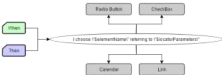
The problem raised in such processes is that there is not a common ground to specify scenarios for each model. They can be freely described following few or no templates, from informal descriptions such as textual narratives until more formal ones such as pre-formatted lists of tasks extracted from task models. It makes very hard the work of identifying similar requirements that eventually describe the same features but in different perspectives. To tackle this problem, we explore the use of the ontological support proposed by Silva et al. [21] aiming describing common behaviors with a standard vocabulary for writing User Stories as scenario artifacts. The main benefit of this strategy is that User Stories described following a common vocabulary can be directly automated for running test scenarios on other artifacts. As the common vocabulary has been set using well-established concepts such as UsiXML [11], W3C MBUI [18] and others, it establishes indeed the searched common ground for a scenario-based approach considering multiple artifacts. The ontology covers concepts related to graphical components (presentation and behavior) used to build web and mobile applications. It also models concepts describing the structure of User Stories, tasks, scenarios and prototypes. As illustrated by Figure 3, the specification of behaviors encompasses when the interaction can be performed (using Given, When and/or Then clauses) and which graphical elements (i.e. Radio Button, CheckBox, Calendar, Link, etc.) are suitable to implement the expected system behavior. In the example, the behavior receives two parameters: an “elementName” and a “locatorParameters”. The first parameter is associated to data for testing, while the second parameter refers to the interaction element supported by this behavior, in this case: “Radio Button”, “CheckBox”, “Calendar” and “Link”. To comply with semantic rules, the behavior “I chose \”$elementName\” referring to
\”$locatorParameters\”” shown in Figure 3 can be modelled
into a predefined behavior “chooseReferringTo”, called Common Step.
Figure 3. Behavior being mapped to UI Elements (from Silva et al. [21]).
The ontological model describes only behaviors that report steps performing actions directly on the user interface through interaction elements. This is a powerful resource because it allows keeping the ontological model domain-free, which means it is not subject to particular business characteristics in the User Stories, promoting the reuse of steps in multiple scenarios. Thus, steps can be easily reused to build different behaviors for different scenarios.
Based on the presented strategy, we set out four main challenges for implementing this approach as follows: (i) adhere to a model-based approach for describing artifacts produced along the process; (ii) teams must be willing to adopt the template for User Stories as well as the vocabulary proposed in the ontology; (iii) the ontology must be expressive enough to cover the UI-supported set of interactive behaviors; and (iv) tests must be carried out by our set of tools.
Target Stakeholders
Many stakeholders are typically involved in the development of interactive systems. Table 1 summarizes their typical activities when modeling interactive system and the benefits they can get from using our proposed approach.
Stakeholders Activity Benefit
Client Define business and user requirements.
Requirements and automated acceptance testing implemented in a
natural and high-level language. Product Owner
and Business Analyst
Write User Stories and define the business
model.
A reliable and consistent compatibility between
User Stories and business models. Requirements and
Test Analyst
Write and format User Stories and help to design task models.
A common and standard vocabulary for writing
and formatting User Stories.
Designers Design task models and UI prototypes.
A reliable and consistent compatibility between
task models and UI prototypes.
Table 1. Target stakeholders of the approach. CASE STUDY
In order to conduct a proof of concept for our approach, we propose a case study in the flight tickets e-commerce
domain. In the following subsections, we present a part of this case with the business process modeling using BPMN, the task modeling using HAMSTERS, the set of resultant scenarios formatted as User Stories, and finally the user interface prototyping using a sketching tool. Both modeling and testing activities have been carried out by the authors of this study.
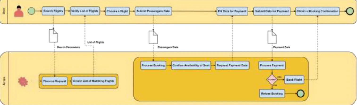
Modeling the Business Process View
Figure 4 presents the BPMN model for the case study. At the top, in the first lane, we have the set of activities performed by users. In the second lane, we have the set of activities performed by the airline company. At first, the set of activities performed by the airline company could be made either manually or in an automated way (using a software system). For this study, we are assuming that the choice is to conduct these activities in an automated way, using a web software system. The online booking process of flight tickets is divided in 2 main sub-processes. The first one is the search of flights based on a provided set of parameters and the consequent selection of the desired flight(s) in a list of matching flights. The second one is the process of booking effectively, providing both passengers and payment data to conclude the booking. The set of functional requirements assumed by the system is described below through a narrative scenario:
The user starts the process by conducting a search of flight based on his desired parameters like origin and destination, dates, number of passengers, etc. This set of parameters is then submitted to the airline system that will process the request and creates a list of matching flights. The list of flights is then returned to the user that verify this list and chooses a flight that better suit his needs. After choosing the desired flight, the user provide all passengers data to the airline system that will process the booking. Thereby, the system confirms the availability of seats and request user to provide payment data. After the user filling and submitting the data for payment, the system processes the payment. If the payment is accepted, then the booking is completed, the user obtains a booking confirmation and the process finishes. If the payment is declined, then the booking is refused and the process finishes as well.
Modeling the Task Model View
We have manually modeled the tasks for the general business process for booking tickets presented in the previous subsection. We have selected the first sub-process for the
study once it is the most interactive one and represents the main source of cognitive efforts from users and designers. The second sub-process, being simply a data providing in forms, is not so relevant to demonstrate the concepts presented in the paper, even though the whole process could be supported by our approach. The task models for the process of searching and choosing flights have been modeled using the HAMSTERS notation.
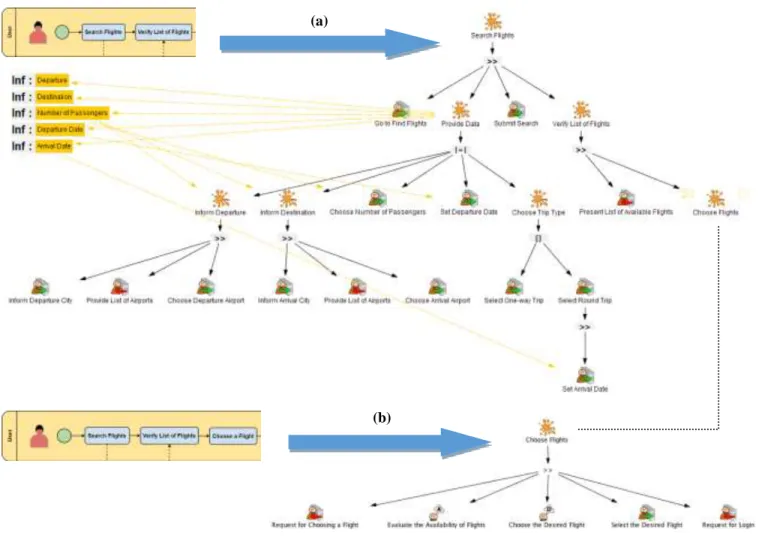
Figure 5 presents respectively the extract of the business process selected for modeling and the resultant task models. In the transition (a), the initial business activity “Search Flights” has been mapped to the abstract/iterative task “Search Flights” once it is performed by the user. This task is exploited in an ordered sequence of input/output tasks. First, the user goes to the web page where he provides data for search, then he provides a set of data for searching his flights, submits the search, and finally verifies the resultant list of flights. Those are sequential user tasks (operator “Enable”). For the abstract task “Verify List of Flights”, the system actually provides the list of available flights and then the subtask “Choose Flights” becomes available to be performed by the user. It matches with the business activity “Verify List of Flights” in the BPMN model.
For providing the set of data for searching (“Infs:”), the user can inform in any other (operator “Order independent”): departure, destination, number of passengers, departure date, and trip type. The abstract tasks “Inform Departure” and “Inform Destination” originate a sequence of three tasks. The first one in which the user informs a departure (or arrival) city, the second one in which the system provides a list of airports in that city, and finally the third one in which the user chooses the departure (or arrival) airport. The abstract task “Choose Trip Type” is actually a decision task once the user can choose (operator “Choice”) between a one-way and a round trip. If he chooses a round trip, he needs to inform the arrival date as well.
In the transition (b) of Figure 5, we present the sequence of the flow. The business activity “Choose a Flight” has been mapped to the abstract/interactive task “Choose Flights” in the task model (notice that this same task has already been
represented as the last abstract task in the first transition). Exploiting the task “Choose Flights”, the system requests user for choosing a flight, then the user evaluates the availability of flights (cognitive analysis task), and finally he makes a decision, choosing the desired flight (cognitive decision task). After the cognitive decision about which flight to choose, the user finally performs the input task of selecting the desired flight. As a result, the system asks the user to provide his login information to proceed the booking with passengers and payment data.
Notice that business and task models are complementary. The business process model provides an overview of the activity flow of the system, emphasizing high-level processes involving diverse business actors. In a different way, the task model is more focused in describing detailed user tasks while interacting with the system, emphasizing lower level tasks. Thereby, task models provide more refined resources and descriptors to model user interactions than those provided by business process models.
Extracting User Stories and Scenarios
Based on the task model developed for the process of searching and choosing flights, we have automatically extracted some possible scenarios that a user could perform
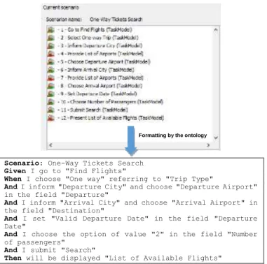
in the system. HAMSTERS tool supports innately the extraction of scenarios from task models, by running them and extracting the possible achievable paths. Figure 6 illustrates an extraction result. The presented path simulates a scenario for a one-way trip. The ordered sequence of tasks for this scenario is listed at the top. This scenario is then manually formatted to meet the User Story template, with each ordered task being mapped to a testable interactive behavior described in the ontology.
Hereafter, we present two formatted User Stories. The first story focuses on the process of searching flights, with a narrative describing the role involved with the history, the feature that this history describes in the user’s point of view, and finally the benefit that this feature brings to the user in terms of business goals. In the first scenario for this history (“One-Way Tickets Search”, presented above), the expected result for the search is a new screen presenting a “List of Available Flights”, in which the user might select the desired flight in a list of flights matching his search. The second scenario (“Search for a return flight before a departure flight”) describes the behavior for a specific business rule, simulating an error situation when searching for a return flight before a departure flight. The expected outcome is the impossibility to search flights. Notice that this last scenario
(b) (a)
has been specified with its respective testing data while the first one has been specified only with data domains.
Scenario: One-Way Tickets Search Given I go to "Find Flights"
When I choose "One way" referring to "Trip Type"
And I inform "Departure City" and choose "Departure Airport" in the field "Departure"
And I inform "Arrival City" and choose "Arrival Airport" in the field "Destination"
And I set "Valid Departure Date" in the field "Departure Date"
And I choose the option of value "2" in the field "Number of passengers"
And I submit "Search"
Then will be displayed "List of Available Flights"
Figure 6. Scenarios being extracted from task models and then being formatted by the ontology as User Stories.
User Story: Flight Tickets Search Narrative:
As a user
I want to be able to search tickets, providing locations and dates.
So that I can obtain information about rates and times of flights.
Scenario: One-Way Tickets Search (…)
Scenario: Search for a return flight before a departure flight
Given I go to "Find Flights"
When I choose "Round trip" referring to "Trip Type" And I inform "New York" and choose "NYC-New York, NY" in the field "Departure"
And I inform "Los Angeles" and choose "LAX-Los Angeles International, CA" in the field "Destination"
And I try to set "12/15/2017" in the field "Departure Date" And I try to set "12/10/2017" in the field "Arrival Date" Then will not be possible to search flights
User Story: Select the desired flight Narrative:
As a frequent traveler
I want to get the list of flights and their rates and times So that I can select the desired flight after a search of available flights.
Scenario: Select a diurnal flight One-Way Tickets Search
Given "Flights Page" is displayed
When I click on "Flights" referring to "AA flight 6557, AA flight 51"
Then "Optional log in" is displayed
The second history focuses on the process of choosing a flight in a list of available flights. The scenario “Select a diurnal flight”, using the Scenario “One-Way Tickets Search”, simulates the selection in the list of available flights, a couple of diurnal flights, the AA6557 and the AA51. For this case,
the behavior expected from the system is the presentation of a new screen with the “Optional log in” message, indicating the user is able to login in order to proceed to the booking, filling the passengers and payment data, which is in line with both business and task models.
Designing the Prototype View
For designing prototypes, we have chosen the sketches produced by Balsamiq Mockups. Balsamiq is a rapid wireframing tool that reproduces the experience of sketching on a whiteboard, but using a computer. Figure 7 presents the scenario “One-Way Tickets Search” supporting the development of a sketch prototyped for the User Story “Flight Tickets Search”.
Scenario: One-Way Tickets Search Given I go to "Find Flights"
When I choose "One way" referring to "Trip Type"
And I inform "Departure City" and choose "Departure Airport" in the field "Departure"
And I inform "Arrival City" and choose "Arrival Airport" in the field "Destination"
And I set "Valid Departure Date" in the field "Departure Date"
And I choose the option of value "2" in the field "Number of passengers"
And I submit "Search"
Then will be displayed "List of Available Flights"
Figure 7. Sketch for the User Story “Flight Tickets Search” built from the scenario “One-Way Tickets Search”.
By using the ontology, the prototype can be manually designed already considering the set of interactive elements supported by each behavior. For example, the behavior “goTo” in the first step (“I go to ‘Find Flights’”) is supported only by the interaction element Browser Window. Thus, the designer has no other option to address this behavior. Indeed, in the prototype, it has been used a Browser Window for this behavior. On the other hand, the fifth step (“I set ‘Valid
Departure Date’ in the field ‘Departure Date’”) addresses
the interaction element “Departure Date” that refers in the prototype to the Calendar used for picking up a date of departure. The behavior “setInTheField” is also supported by Dropdown Lists, Text Fields and Autocompletes. Thus, the designer could have picked any of them instead, but not a Button, for instance, once it does not support the behavior “setInTheField”. Following the mapping, the second step addresses the interaction element “Trip Type” that refers to the Link bar used for choosing between a one-way and a
1 2 3 4 5 6 7
Designing the prototype
1
2
3 4 6
7 5
round trip. The third and fourth steps addresses the interaction elements “Departure” and “Destination” that share the same interactive behavior, so the designer can simply reuse it for both elements in order to keep the semantic consistency of the interaction. A Text Field with a searching feature has been chosen. It means that this element supports an operation autocomplete where, with a single interaction, the user attains to inform some partial text and (based on the instant matching results) choose the desired option. The sixth step addresses the interaction element “Number of passengers” that refers to the Combo Box used for choosing the number of passengers in a finite list. Finally, the seventh step addresses the interactive element “Search” that refers to the Button used for submitting the search.
Mapping Elements for Testing
The testing of UI design artifacts is conducted by automatically checking whether requirements have been consistently modeled. Table 2 exemplifies the correspondence of concepts in the models and in the ontology. In the example, the consistency of the requirements representation of the interaction element “Departure Date”, used in the prototype, is being checked in the other requirements artifacts until reaching the high-level business activity “Search Flights”.
Artifact
Concepts Step of Scenario Model Ontology
BPMN Model Activity: Search
Flights Event: When When I set “Valid Departure Date”
in the field “Departure Date” Task Model Input Task: Set
Departure Date Behavior: SetInTheField Prototype UI Element: Departure Date Interaction Element: Calendar
Table 2. Example of concept mapping for testing.
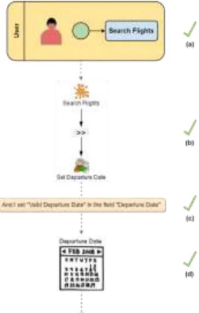
Figure 8 illustrates the testing path covering an extract of the BPMN model (a), task model (b), scenario (c), and prototype (d). Following the approach presented above, the first results of testing have shown, for example, that the step “Given I go
to ‘Find Flights’” has been correctly attended by all business
process model, task model and prototype. It means that there is an activity in the business process model (“Search Flights”), a task in the task model (“Go to Find Flights”), and an interaction element (“Browser Window”) in the prototype to attend properly this step. Our approach has also identified some important inconsistencies in the artifacts under testing. The second step of the two first scenarios (“When I choose
‘One way/Round trip’ referring to ‘Trip Type’”) has failed in
the prototype. This Step has failed because regardless presenting a proper Link bar for selecting a one-way or round trip, the element cannot be identified as belonging to “Trip Type”. It lacks a label in the prototype to identify it. Notice that, in the task model, if the correspondent task “Choose Trip Type” had been defined by an operator “Enable” after the sequence of tasks to inform departure, destination and
dates, the test would fail. As this operator determines sequential tasks, the model would be conflicting with the sequence determined in the scenario.
Figure 8. Extract of the testing path in the artifacts.
The last step of the two first scenarios (“Then will be
dis-played ‘List of Available Flights’” and “Then will not be possible to search flights”) has also failed when testing the
prototype. Once the dialog component (dynamic behavior) is not conceived yet, we cannot check if the outcome of those scenarios would be respectively the list of available flights and the impossibility to search flights. The last step of the second scenario has also failed for the task model. As user errors are not part of a user goal, they are usually omitted from tasks descriptions, making this kind of test fails. Means of representing these potential errors on task models is being recently studied [7]. Once it is implemented in the model, tests could run using the same approach to identify this kind of error. Finally, all of the other remaining steps were successfully performed and passed the tests. Notice that once some step of scenario fails, the scenario is considered as failed as well.
RELATED WORKS
Language Extended Lexicon (LEL) [10] has used natural language for specifying requirements since the 90’s. The authors propose a lexical analysis of requirements descriptions in order to integrate Scenarios into a requirements baseline, making possible tracing their evolution. They were followed by several attempts to identify test cases from requirements specified in natural language [6] [22]. Several authors [2] [3] [12] [26], on the other hand, concentrate efforts in providing automated tools to keep compatibility between different artifacts models. Those approaches, regardless providing some mechanism to trace or assess requirements for particular environments, do not consider how to integrate and test the set of multiple other artifacts that are commonly used throughout development processes.
Luna et al. [12] propose WebSpec, a requirement artifact used to capture navigation, interaction and UI features in web applications, where diagrams can be validated due to the automatic derivation of interaction tests. Wolff et al. [26] pro-poses to link GUI specifications to abstract dialogue models describing behavioral characteristics. This approach provides an interesting mechanism to control changes in interface elements, however the approach is not iterative and does not provide the necessary testing component to check and verify user interfaces against predefined behaviors from requirements. Buchmann and Karagiannis [2] presented a modeling method for the elicitation and validation of requirements for mobile apps that enables semantic traceability for the requirements representation, but using an extremely heavy modeling approach that is not suitable to check requirements in a high level of abstraction, validating only requirements that were modeled within the approach. Campos et al. [3] propose a model-based testing approach to support linking task models to an existing, executable, interactive application. The method allows defining a systematic correspondence between the user interface elements and user tasks. The problem with this approach is that it only covers the interaction of task models with final UIs, not covering early artifacts. Another problem is it requires much intervention of developers to prepare the source code to support the integration, making it difficult to be adopted in applications that cannot receive interventions in the code level. Lastly, Valente et al. [24] propose an approach considering User Stories for bridging business process and user tasks, but aiming support enterprise modeling and software architecture. The authors propose an approach called Goals Approach that focus on how to obtain a goals business model of requirements based on the DEMO method. The approach however is aimed to address the process issues, not covering the assessment aspects.
CONCLUSION AND FUTURE WORKS
Even being preliminary, the results we have obtained so far are quite promising. Addressing the four challenges we stated when presenting the approach and based on such results, we can highlight a set of advantages and some shortcomings. Concerning the adherence to a model-based approach, this approach benefits from the independence for testing artifacts. Artifacts do not need to be prepared for testing, neither be part of some development process to be tested. Once the approach is suited to run with any software development process, testing can be conducted in an independent manner, only in the set of artifacts designed at a given time, which benefits early artifacts. However, so far we are only covering artifacts modeled in BPMN, HAMSTERS and Balsamiq. We also did not evaluate yet the impact of maintaining and evolving such artifacts throughout the development process.
Concerning the adoption of the template for User Stories and the vocabulary proposed in the ontology, an advantage is that requirements and tests in User Stories are kept in a natural
and high-level language. Keeping them as such helps to establish a common vocabulary for the whole team, and allows non-technical stakeholders to effectively participate at the specification and testing processes. Although this study does not cover evaluation with potential users, ongoing work aims to investigate the use of the approach in a broader case study with Product Owners, evaluating the workload, the maintainability and the scalability of the approach. Concerning the expressiveness of the ontology, an advantage is that the approach is domain-independent, once the low-level interactive actions on UI elements (such as clicks, selections, settings, etc.) are the same regardless the application domain. Another advantage is the plurality of interaction elements modeled by the ontology used. As many of them can answer the same behavior, even if a Combo Box has been chosen to attend some behavior in a previous prototype, an Auto Complete field could be chosen to attend this behavior on a further and more refined version, once both elements share the same ontological property for the behavior under testing. A shortcoming we have identified is related to the restricted vocabulary of the ontology. Even with the ontology mapping synonyms for some specific behaviors, it does not provide any kind of semantic interpretation, i.e. the behaviors must be specified on stories exactly as they were defined. At a first glance, nonetheless, the restricted vocabulary seems to bring less flexibility to designers, testers and requirements engineers, but at the same time, it establishes a common vocabulary, avoiding typical problems of ambiguity and incompleteness in requirements and testing specifications.
Finally, concerning our tools, one of the advantages they provide is the fine-grained testing coverage. Each small modification in the User Stories or in the artifacts is able to be captured during the testing process. The use of data-independent scenarios is another advantage. Data can be specified through data domains to be injected on runtime (like in “One-Way Tickets Search”), or directly in the scenario description (like in “Search for a return flight before a departure flight”). The first strategy is very useful in the beginning of the project, when typically there are few definitions about representative data for testing. A limitation in our set of tools, however, is the absence of classification for errors. There is currently no distinction between the different reasons of test failure (e.g. UI element not found, behavior not supported, etc.). As shown in the case study, our approach signalize in which step of the scenario some inconsistency has been found, but do not classify it according to the solution that should be employed to solve the problem. Classifying errors would help to better identify if a given inconsistency detected is due to an actual error in the requirements representation or if it is due just to a limitation of the artifact. Our planned future works envision tackling this issue, besides conducting new studies involving more complex interactive behaviors, an increase of ontological expressiveness, and interactions in different contexts beyond the web.
REFERENCES
1. Michel Beaudouin-Lafon and Wendy Mackay. 2002. Prototyping tools and techniques. In The
human-computer interaction handbook, L. Erlbaum Associates
Inc., Hillsdale, NJ, USA, 1006-1031.
2. Robert A. Buchmann and Dimitris Karagiannis. 2015. Modelling Mobile App Requirements for Semantic Traceability. Requirements Engineering 22, 1: 1-35. 3. José C. Campos, Camille Fayollas, Célia Martinie,
David Navarre, Philippe Palanque and Miguel Pinto. 2016. Systematic automation of scenario-based testing of user interfaces. In Proceedings of the 8th ACM
SIGCHI Symposium on Engineering Interactive Computing Systems, 138-148.
4. Mike Cohn. 2004. User Stories Applied: For Agile
Software Development. Addison-Wesley Professional.
5. Adrien Coyette, Suzanne Kieffer and Jean
Vanderdonckt. 2007. Multi-fidelity Prototyping of User Interfaces. In Proc. of the IFIP TC.13 International
Conference on Human-Computer Interaction, 150-164.
6. Anurag Dwarakanath and Shubhashis Sengupta. 2012. Litmus: Generation of Test Cases from Functional Requirements in Natural Language. In Int. Conference
on Application of Natural Language to Information Systems, 58-69.
7. Racim Fahssi, Célia Martinie and Philippe Palanque. 2015. Enhanced Task Modelling for Systematic Identification and Explicit Representation of Human Errors. In Proc. of the IFIP TC.13 International
Conference on Human-Computer Interaction, 192-212.
8. Object Management Group. 2011. Business Process Model And Notation™ (BPMN™). Retrieved August, 2017 from http://www.omg.org/spec/BPMN/2.0/ 9. Michael Havey. 2005. Essential Business Process
Modeling. O'Reilly Media, Inc.
10. Julio C. S. P. Leite and Antonio P. A. Oliveira. 1995. A Client Oriented Requirements Baseline. In Proc. of the
2nd IEEE International Symposium on Requirements Engineering (RE'95), 108-115.
11. Quentin Limbourg, Jean Vanderdonckt, Benjamin Michotte, Laurent Bouillon and Víctor López-Jaquero. 2004. USIXML: a Language Supporting Multi-Path Development of User Interfaces. In Proc. of the
EHCI-DSVIS, 200-220.
12. Esteban R. Luna, Irene Garrigós, Julián Grigera and Marco Winckler. 2010. Capture and Evolution of Web Requirements Using WebSpec. In Proc. of the Int.
Conference on Web Engineering, 173-188.
13. Célia Martinie, Philippe Palanque and Marco Winckler. 2011. Structuring and Composition Mechanisms to Address Scalability Issues in Task Models. In Proc. of the IFIP TC.13 International
Conference on Human-Computer Interaction, 589-609.
14. Rudolf van Megen and Dirk B. Meyerhoff. 1995. Costs and benefits of early defect detection: experiences from developing client server and host applications.
Software Quality Journal 4, 4: 247-256.
15. Dan North. 2017. What's in a Story?. Retrieved August, 2017 from http://dannorth.net/whats-in-a-story/
16. Fabio Paternò, Carmen Santoro, Lucio D. Spano and Dave Raggett. 2017. W3C, MBUI - Task Models. Retrieved August, 2017 from
http://www.w3.org/TR/task-models/
17. Florence Pontico, Christelle Farenc and Marco Winckler. 2006. Model-Based Support for Specifying eService eGovernment Applications. In Proc. of the
International Workshop on Task Models and Diagrams for User Interface Design, 54-67.
18. Jaroslav Pullmann. 2017. W3C, MBUI - Glossary. Retrieved August, 2017 from
http://www.w3.org/TR/mbui-glossary/
19. Mary B. Rosson and John M. Carroll. 2002. Usability
Engineering: Scenario-Based Development of Human-Computer Interaction. Morgan Kaufmann.
20. Ken Schwaber. 2004. Agile Project Management with
Scrum. Microsoft Press.
21. Thiago R. Silva, Jean-Luc Hak and Marco Winckler. 2017. A Behavior-Based Ontology for Supporting Automated Assessment of Interactive Systems. In
Proc. of the 11th IEEE International Conference on Semantic Computing, 250-257.
22. Harry M. Sneed. 2007. Testing against Natural Language Requirements. In Proc. of the Seventh IEEE
International Conference on Quality Software (QSIC
2007), 380-387.
23. Eero J. Uusitalo, Marko Komssi, Marjo Kauppinen and Alan M. Davis. 2008. Linking Requirements and Testing in Practice. In Proc. of the IEEE Int.
Requirements Engineering Conference, 265-270.
24. Pedro Valente, Thiago Silva, Marco Winckler, and Nuno Nunes. 2016. Bridging Enterprise and Software Engineering Through an User-Centered Design Perspective. In Proc. of the International Conference
on Web Information Systems Engineering, 349-357.
25. Marco Winckler and Philippe Palanque. 2012. Models as Representations for Supporting the Development of e-Procedures. In Usability in Government Systems –
User Experience Design for Citizens and Public Servants, Morgan Kaufmann Publishers, 301-315.
26. Andreas Wolff, Peter Forbrig, Anke Dittmar and Daniel Reichart. 2005. Linking GUI Elements to Tasks: Supporting an Evolutionary Design Process. In
Proc. of the 4th International Workshop on Task Models and Diagrams, 27-34.
View publication stats View publication stats
![Figure 1. An overview of the scenario-based design (SBD) framework (from Rosson & Carroll [19])](https://thumb-eu.123doks.com/thumbv2/123doknet/13435963.409234/3.918.109.411.662.898/figure-overview-scenario-based-design-framework-rosson-carroll.webp)