HAL Id: hal-01123802
https://hal.archives-ouvertes.fr/hal-01123802
Submitted on 15 May 2019
HAL is a multi-disciplinary open access
archive for the deposit and dissemination of
sci-entific research documents, whether they are
pub-lished or not. The documents may come from
teaching and research institutions in France or
abroad, or from public or private research centers.
L’archive ouverte pluridisciplinaire HAL, est
destinée au dépôt et à la diffusion de documents
scientifiques de niveau recherche, publiés ou non,
émanant des établissements d’enseignement et de
recherche français ou étrangers, des laboratoires
publics ou privés.
The microfluidic puzzle: chip-oriented rapid prototyping
Jiseok Lim, Florine Maes, Valérie Taly, Jean-Christophe Baret
To cite this version:
Jiseok Lim, Florine Maes, Valérie Taly, Jean-Christophe Baret. The microfluidic puzzle: chip-oriented
rapid prototyping. Lab on a Chip, Royal Society of Chemistry, 2014, 14 (10), pp. 1669-1672.
�10.1039/c3lc51399h�. �hal-01123802�
TECHNICAL INNOVATION
Cite this:Lab Chip, 2014, 14, 1669
Received 18th December 2013, Accepted 19th February 2014 DOI: 10.1039/c3lc51399h www.rsc.org/loc
The microfluidic puzzle: chip-oriented
rapid prototyping
†
Jiseok Lim,
abFlorine Maes,
aValérie Taly
cand Jean-Christophe Baret
‡*
aWe demonstrate a new concept for reconfigurable microfluidic devices from elementary functional units. Our approach suppresses the need for patterning, soft molding and bonding when details on a chip have to be modified. Our system has two parts, a base-platform used as a scaffold and functional modules which are combined by ‘plug-and-play’. To demonstrate that our system sustains typical pressures in microfluidic experiments, we produce droplets of different sizes using T-junction modules with three different designs assembled successively on a 3× 3 modular scaffold.
Microfluidics is based on the manipulation of fluid at small scales.1,2 Over the past 20 years, by miniaturization and automatization, new experiments have become feasible, from the manipulation and assay of single cells,3–6genes,7,8or enzymes9 to the manipulation of complex multicellular organisms10–12 and reconstitution of artificial organs.13An essential ingredient in the development of microfluidics is rapid prototyping by soft-lithography which provides microfabrication methods to produce microfluidic chips with an almost infinite number of degrees of freedom.14,15 By miniaturizing fluidic components down to the micro-meter scale, many functional modules can be integrated on a single chip– be it for single phase flow or multiphase flow– towards specific preprogrammed actions.6,16–18 However, the flexibility at the core of the soft-lithography techniques relies on manufacturing capabilities such as clean rooms found in specific laboratories and in technological indus-tries equipped with state-of-the-art microfabrication techniques. The lack of availability of microfluidic chips is very often a hurdle that limits small business units or academic laborato-ries to develop microfluidic tools suitable for their needs. The electronic industry– which in the past provided the techno-logical basis for soft lithography14– provides here again the basic idea for a novel rapid prototyping method. Electrical test boards are indeed common in many laboratories to design,
create and test electric circuits from a finite set of functional elements, such as power supplies, resistances, inductances, transistors, capacitors, and memory among others. Although limited in functionalities, these elements can be assembled at will to produce complex functionalities over the whole circuit board.
We introduce here a new concept of modular microfluidics based on a plug-and-play construction, analogous to the electrical test boards. The concept of the system is based on the combi-nation of microfluidic modules which are pre-manufactured and assembled separately in a platform. Users can define the structures of the microfluidic devices and easily change a detail of the chip without the need to redo a photolithography step. Our chip-oriented rapid prototyping method can contribute to the standardization of microfluidic devices:19 large series of functional elements can be manufactured, with the integration of the final chip being the task of the end-user. We show an example based on droplet production in which the same platform is used to produce droplets of different sizes by simply replacing the functional element, demonstrating a reconfigurable, leakage-free system for multiphase flow work-ing at a typical pressure reached in microfluidic chips.
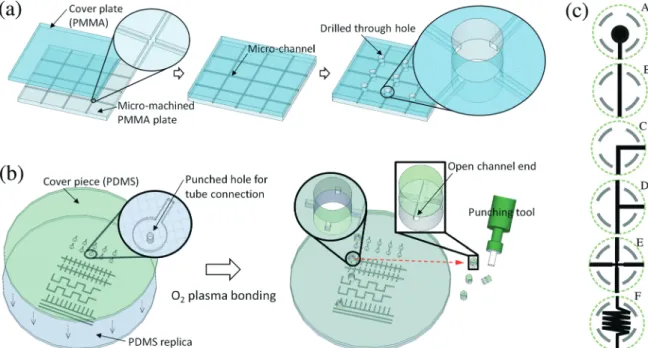
The system is composed of a micro-machined rigid plat-form (the scaffold) and elastic modules which are fabricated by conventional soft lithography in polydimethylsiloxane (PDMS, the functional units) as described in Fig. 1. The scaffold is made of two polymethylmethacrylate (PMMA) thin sheets (3 mm thick). In one of the plates, two sets of parallel lines with a width of 500μm and a height of 500 μm are micromachined using a high precision drill (DMU 50, DMG Mori Seiki). The plate is then bonded to the second flat PMMA sheet of the same thickness (3 mm) by thermal bonding processes. Before bonding, the PMMA plates were plasma-treated in an O2plasma-chamber (Diener) for 30 s at 0.4 mbar and 140 W.
The bonding was performed at a temperature of 98 °C, with an applied force of 5 kN for 30 min (P/O Weber). The scaffold
a
Droplets, Membranes and Interfaces, MPI for Dynamics and Self-organization, Am Fassberg 17, 37077 Göttingen, Germany. E-mail: [email protected]; Web: http://dmi.ds.mpg.de
bMax Planck Institute for Biophysical Chemistry, Am Fassberg 11, 37077 Göttingen, Germany
c
Université Paris Sorbonne Cité, INSERM UMR-S775, Centre Universitaire des Saints-Pères, 45 rue des Saints-Pères, 75270 Paris Cedex 06, France
† Electronic supplementary information (ESI) available: Movies of droplet production with different T-junction modules and CAD designs of the functional units are available as supplementary files. See DOI: 10.1039/c3lc51399h ‡ Present Address: Université de Bordeaux and Centre de Recherche Paul Pascal – CNRS (Pessac, France)
Open Access Article. Published on 24 March 2014. Downloaded on 5/14/2019 3:32:27 PM.
This article is licensed under a
Creative Commons Attribution 3.0 Unported Licence.
View Article Online
was then cooled down to room temperature at a rate of approximately−1 °C min−1to slowly relax the thermal stresses. 9 through holes (diameter 4.6 mm) were drilled in the scaffold and the scaffold was cleaned with ethanol to remove the debris generated during the drilling process.
The functional modules are fabricated by standard soft lithography14 in a 25μm deep SU-8-3025 resist by directing UV light through a transparent mask (Selba, Switzerland). The mask is designed with circular alignment marks and connection branches spaced by 90° angles from the center of the circle. Fig. 1(c) shows the functional unit made for example of injectors and outlets (A), linkers (B, C), a T-junction (D), a flow-focusing junction (E), and incubation lines (F). Each module carries a specific connectivity to the scaffold, blocking undesired connections. The SU-8 structure is then replicated in polydimethylsiloxane (PDMS) from the master. Connection holes are punched in the PDMS if required by the design, for example in the case of inlets and outlets. A second PDMS slab is cast on a flat wafer and both PDMS slabs are bonded together after O2-plasma treatment. The PDMS functional units
are cut using a 5 mm diameter biopsy punch. Alignment of the channels with the biopsy punch is crucial here to guarantee the alignment of the channels of the functional units with the channels of the scaffold. The diameter of the scaffold holes was chosen after optimization, testing through hole diam-eters ranging from 4 to 5 mm with 100 μm steps. The final combination of 5 mm (biopsy hole) and 4.6 mm (scaffold hole) diameters provides a tight sealing between the PMMA scaffold and the PDMS module.
We used a 3 × 3 PMMA scaffold and a set of functional modules to produce droplets at a T-junction. We used four functional modules assembled as shown in Fig. 2(a). The PDMS
modules are lubricated by fluorinated oil prior to insertion into the scaffold. The rotational tolerance for alignment between the channel on the scaffold and the structure on the modules is given by the channels of the scaffold and modules. The rotational tolerance was calculated as 12° based on the geo-metrical dimensions (Fig. 2(g)). The translational tolerance is Fig. 1 Modular fabrication of a microfluidic chip. (a) PMMA scaffold fabrication process and (b) PDMS functional modules. (c) Schematic representation of the functions for the functional units (A: inlet/outlet, B, C: linkers, D: T-junction, E: flow focusing, F: incubation line).
Fig. 2 Integration of functional units in the scaffold. The units are simply inserted in the scaffold in a ‘plug-and-play’ manner. The elasticity of the PDMS provides tight connections and alignment is achieved by eye. (a) Empty hole, (b) inlet/outlet, (c, d) linkers, (e) T-junction, and (f) flow-focusing junction. Possible misalignment between the functional units and scaffold; (g) rotational and (h) translational misalignment.
Lab on a Chip Technical Innovation
Open Access Article. Published on 24 March 2014. Downloaded on 5/14/2019 3:32:27 PM.
This article is licensed under a
Creative Commons Attribution 3.0 Unported Licence.
mainly defined by the eccentric error during the fabrication of the module (Fig. 2(h)). The tolerances are sufficient to make the connection alignment by eye (for the perpendicular align-ment tolerance, see Fig. S1.†). The expanded channel design at the interface of the module and platform, and the addi-tional align-key around the module help with the alignment during plug-in. Fig. 2(a–f) show examples of different modules which are integrated with the platform without any additional alignment tools.
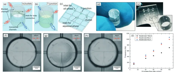
To show the plug-and-play capability of our method, we demonstrate droplet production by assembling two inlet modules for the aqueous phase and oil phase, one outlet module and a T-junction module (Fig. 3(a–e)). We used water and fluorinated oil with a surfactant (HFE7500 (Novec) with 0.5% PEG–PFPE block-copolymer (Sigma-Aldrich, custom synthesis) as the emulsification system. By replacing the T-junction module with three different nozzle sizes of 100μm, 60 μm and 40μm, droplets with different sizes were successfully produced as shown in Fig. 3(f–h). To evaluate the production reliability, the system was tested with different flow rates. Fig. 3(i) shows the frequencies of the production with a fixed flow rate of 10μL min−1for the water phase and flow rates in the range of 10–100 μL min−1for the oil phase.
We demonstrate here the concept of the integration of microfluidic systems with a chip-oriented approach. The most critical issue for the creation of functional units is punching off-center. The error of the punching position will cause misalignment between the functional modules and the scaf-fold. Here, we performed the punching process using a very crude alignment procedure using a paper guide having the size and pitch of the design. Even with this procedure, properly functional systems are obtained, because the tolerance is finally given by the dimensions of the channels of the scaffold. However, it is clear that mass production of single elastomeric
elements and mechanical control of the punching will reduce this limitation. The second limitation is the size of the scaffold, currently limited by the size of the thermal bonding system used here. Optimizations of the scaffold design, e.g. having a hexagonal arrangement of the holes, could increase to ~25 the number of functional units that can be integrated. Here again, our system would benefit from large scale integration, which is in principle accessible with minor engineering improvements. Only the size of the scaffold will determine the final size of the chip, which could therefore be of a much larger size than what is currently accessible in soft-lithography.
The advantages that we have shown on tuning the droplet size can be further extended to other aspects, such as having localized wettability alterations, which would make the pro-duction of double emulsions relatively straightforward. The single functional units could be made available as hydro-philic or hydrophobic, in addition to having several dimen-sions. Our system can also provide solutions for on-chip storage modules, valves and three-dimensional assembly. Electrodes for sorting and coalescence could also be inserted for example using the microsolidics technique,20 and the modules currently fabricated by standard soft-lithography could be manufactured by other means (for example xurography21). Our system is reminiscent of the one proposed by Rhee et al.22 and Langelier et al.23 and similar functional modules can be designed. However, we solve here the limitations linked to (i) the leakage of fluids since our connections are tight for the typical pressures found in experiments (typically of order 1 bar, see Fig. S2†) and (ii) the reversibility of the assembly process since our modules are inserted on-demand by hand in the scaffold. Our approach also solves technical difficulties linked to the need for intermediate connecting blocks in the previ-ously described SmartBuild systems24 and small feature sized structures.25The mechanical stability of our system is
Fig. 3 Example of the modular microfluidic system for droplet formation using a T-junction. (a) In/outlet module, (b) one T-junction module, (c) integration of four modules on the scaffold. Photograph of the (d) T-junction module and the (e) module integrated scaffold. (f, g, h) Droplet production using three T-junction modules with three different nozzle sizes (100μm (f), 60 μm (g) and 40 μm (h)), and (i) measured frequency of the droplet production. The T-junction modules have simply been replaced on the scaffold between the successive experiments.
Open Access Article. Published on 24 March 2014. Downloaded on 5/14/2019 3:32:27 PM.
This article is licensed under a
determined by the PMMA scaffold and dead-volumes between the elements are also minimized. We believe that our system will find applications as an educational system or as a platform for crowd-sourcing26–29 optimization of devices or innovation through entertaining microfluidic games.30 In this case, molding techniques could be used to convert the simple round shape of our functional units to more attractive shapes as previously proposed.22
In summary, we demonstrate a system for chip-oriented rapid prototyping making use of a PMMA scaffold and func-tional PDMS units. The system provides tight connections between functional elements for customer-oriented integration of microfluidic chips. The system is technologically interesting as the functional units are simple and can in principle be mass produced while the integration by the user will lead to an almost infinite set of possible devices, testable in a very short time and at low cost.
Acknowledgements
We thank the Max Planck Society and the CNRS for financial support. J.-C.B. and F.M. also acknowledge funding support from the European Research Council (ERC) under the European Unions Seventh Framework Program (FP7/2007-2013)/ERC grant no. 306385SofI. We thank W. Keiderling, A. Gerke and W. Schubert at the Workshop facility of the MPIds for technical support and Max Planck Innovation GmbH for helpful support. A patent application related to this system has been filed.
References
1 T. M. Squires and S. R. Quake, Rev. Mod. Phys., 2005, 77, 977–1026.
2 G. Whitesides, D. Janasek, J. Franzke, A. Manz, D. Psaltis, S. R. Quake, C. Yang, H. Craighead, A. deMello, J. El-Ali, P. Sorger, K. Jensen, P. Yager, T. Edwards, E. Fu, K. Helton, K. Nelson, M. Tam and B. Weighl, Nature, 2006,442, 367–418. 3 J.-C. Baret, O. J. Miller, V. Taly, M. Ryckelynck, A. El-Harrak,
L. Frenz, C. Rick, M. L. Samuels, J. B. Hutchison, J. J. Agresti, D. R. Link, D. A. Weitz and A. D. Griffiths, Lab Chip, 2009,9, 1850–1858.
4 J.-C. Baret, Y. Beck, I. Billas-Massobrio, D. Moras and A. D. Griffiths, Chem. Biol., 2010,17, 528–536.
5 B. E. Debs, R. Utharala, I. V. Balyasnikova, A. D. Griffiths and C. A. Merten, Proc. Natl. Acad. Sci. U. S. A., 2012, 109, 11570–11575.
6 L. Mazutis, J. Gilbert, W. L. Ung, D. A. Weitz, A. D. Griffiths and J. A. Heyman, Nat. Protoc., 2013,8, 870–891.
7 E. A. Ottesen, J. W. Hong, S. R. Quake and J. R. Leadbetter, Science, 2006,314, 1464–1467.
8 D. Pekin, Y. Skhiri, J.-C. Baret, D. L. Corre, L. Mazutis, C. B. Salem, F. Millot, A. E. Harrak, J. B. Hutchison,
J. W. Larson, D. R. Link, P. Laurent-Puig, A. D. Griffiths and V. Taly, Lab Chip, 2011,11, 2156–2166.
9 R. Arayanarakool, L. Shui, S. W. M. Kengen, A. van den Berg and J. C. T. Eijkel, Lab Chip, 2013,13, 1955–1962.
10 J. Clausell-Tormos, D. Lieber, J.-C. Baret, A. El-Harrak, O. J. Miller, L. Frenz, J. Blouwolff, K. J. Humphry, S. Koester, H. Duan, C. Holtze, D. A. Weitz, A. D. Griffiths and C. A. Merten, Chem. Biol., 2008,15, 427–437.
11 N. Chronis, Lab Chip, 2010,10, 432–437.
12 J. A. Carr, A. Parashar, R. Gibson, A. P. Robertson, R. J. Martin and S. Pandey, Lab Chip, 2011,11, 2385–2396.
13 D. J. Beebe, D. E. Ingber and J. den Toonder, Lab Chip, 2013, 13, 3447–3448.
14 Y. N. Xia and G. M. Whitesides, Annu. Rev. Mater. Sci., 1998, 28, 153–184.
15 J. R. Anderson, D. T. Chiu, R. J. Jackman, O. Cherniavskaya, J. C. McDonald, H. Wu, S. H. Whitesides and G. M. Whitesides, Anal. Chem., 2000,72, 3158–3164.
16 T. Thorsen, S. J. Maerkl and S. R. Quake, Science, 2002,298, 580–584.
17 L. Mazutis, J.-C. Baret, P. Treacy, Y. Skhiri, A. F. Araghi, M. Ryckelynck, V. Taly and A. D. Griffiths, Lab Chip, 2009,9, 2902–2908.
18 R. Seemann, M. Brinkmann, T. Pfohl and S. Herminghaus, Rep. Prog. Phys., 2012,75, 016601.
19 C. M. Klapperich, Expert Rev. Med. Devices, 2009,6, 211–213. 20 A. C. Siegel, S. S. Shevkoplyas, D. B. Weibel, D. A. Bruzewicz, A. W. Martinez and G. M. Whitesides, Angew. Chem., 2006, 118, 7031 (Angew. Chem., Int. Ed., 2006, 45, 6877).
21 D. A. Bartholomeusz, R. W. Boutte and J. D. Andrade, J. Microelectromech. Syst., 2005,14, 1364–1374.
22 M. Rhee and M. A. Burns, Lab Chip, 2008,8, 1365–1373. 23 S. M. Langelier, E. Livak-Dahl, A. J. Manzo, B. N. Johnson,
N. G. Walter and M. A. Burns, Lab Chip, 2011, 11, 1679–1687.
24 P. K. Yuen, Lab Chip, 2008,8, 1374–1378.
25 T. P. Segato, S. A. Bhakta, M. Gordon, E. Carrilho, P. A. Willis, H. Jiao and C. D. Garcia, Anal. Methods, 2013,5, 1652–1657. 26 M. Lessl, J. S. Bryans, D. Richards and K. Asadullah, Nat.
Rev. Drug Discovery, 2011,10, 241–242.
27 S. Mavandadi, S. Dimitrov, S. Feng, F. Yu, R. Yu, U. Sikora and A. Ozcan, Lab Chip, 2012,12, 4102–4106.
28 F. Khatib, F. DiMaio, F. C. Group, F. V. C. Group, S. Cooper, M. Kazmierczyk, M. Gilski, S. Krzywda, H. Zabranska, I. Pichova, J. Thompson, Z. Popovi, M. Jaskolski and D. Baker, Nat. Struct. Mol. Biol., 2011,18, 1175–1177. 29 F. Khatib, S. Cooper, M. D. Tyka, K. Xu, I. Makedon,
Z. Popovic, D. Baker and F. Players, Proc. Natl. Acad. Sci. U. S. A., 2011,108, 18949–18953.
30 I. H. Riedel-Kruse, A. M. Chung, B. Dura, A. L. Hamilton and B. C. Lee, Lab Chip, 2011,11, 14–22.
Lab on a Chip Technical Innovation
Open Access Article. Published on 24 March 2014. Downloaded on 5/14/2019 3:32:27 PM.
This article is licensed under a
Creative Commons Attribution 3.0 Unported Licence.