HAL Id: hal-02996474
https://hal.archives-ouvertes.fr/hal-02996474
Submitted on 9 Nov 2020
HAL is a multi-disciplinary open access archive for the deposit and dissemination of sci-entific research documents, whether they are pub-lished or not. The documents may come from teaching and research institutions in France or abroad, or from public or private research centers.
L’archive ouverte pluridisciplinaire HAL, est destinée au dépôt et à la diffusion de documents scientifiques de niveau recherche, publiés ou non, émanant des établissements d’enseignement et de recherche français ou étrangers, des laboratoires publics ou privés.
Dipolar self-assembled monolayers grafted on ZnO for
the tuning of electronic properties of the poly
(3-hexylthiophène)- [6,6]-phenyl C61-butyric acid
methylester blend
Mariem Ben Youssef, Philippe Lang, Mahamadou Seydou, Faycal Kouki
To cite this version:
Mariem Ben Youssef, Philippe Lang, Mahamadou Seydou, Faycal Kouki. Dipolar self-assembled monolayers grafted on ZnO for the tuning of electronic properties of the poly (3-hexylthiophène)-[6,6]-phenyl C61-butyric acid methylester blend. Thin Solid Films, Elsevier, 2020, 714, pp.138296. �10.1016/j.tsf.2020.138296�. �hal-02996474�
1
Dipolar Self-assembled Monolayers grafted on ZnO for the tuning
of electronic properties of the poly (3-hexylthiophène)-
[6,6]-phenyl C61-butyric acid methylester blend
Mariem Ben Youssef (a), Philippe Lang*(a), Mahamadou Seydou(a) , Faycal Kouki*(b) (a) ITODYS (UMR 7086), University of Paris (Paris 7), 15 rue Jean-Antoine de Baïf, 75205 Paris
Cedex 13, France
* faycal_kouki@yahoo.fr ; lang@u-paris.fr
(b) LMAPQ, Faculté des Sciences de Tunis, University Tunis El-Manar, 2092 El-Manar, Tunis,
Tunisia
Abstract
A promising solution to improve the performance of Bulk heterojunction organic photovoltaic devices is the insertion of functionalized self-assembled monolayers (SAMs) at the interface between the Electron Transporting Layer (ETL) and the active layer. By grafting such dipolar SAMs based on Y-PP-COOH (P = Phenyl, Y = CH3O, F)) on a ZnO ETL, both the electronic and the
chemical properties of the interface are modified. The growth of the active blend
the poly(3-hexylthiophène)- [6,6]-phenyl C61-butyric acid methylester blend
deposited onto the SAMs is also altered. The dipole with a component oriented perpendicularly to the ZnO surface modifies the ZnO work function whereas the surface energy of the SAM influences the microstructuration of the active material. When we analyze the inverted photovoltaic cell, we find that the two effects may be distinguished: the CH3O moiety favorably affects the electrical
transfer of carriers with mainly an improvement of the open-circuit voltage Voc whereas
fluorine disfavors both electron extraction and blend microstructure quality, with a lower Voc
and electrical current density Jsc.
2
1. Introduction
Organic solar cells (OSCs) based on π-conjugated semiconducting (SC) polymers are becoming potential alternative candidates in the field of photovoltaic conversion since they can be fabricated by cost-effective large-area printing and coating processes on top of flexible substrates [1-3]. Bulk heterojunction (BHJ) solar cells, based on π-conjugated polymers and fullerene-derivative blend layers sandwiched between a transparent conducting electrode, namely Fluoride Tin Oxide (FTO) and a low-work-function metal electrode, have proven to be worthy competitors to polycrystalline silicon-based cells [4-6]. Over the past few years, important results have shown that the performance of OSCs can be enhanced by the development of materials and/or the optimization of morphologies by processing methods [7-10]. The photoinduced charge separation, the charge transport and the collection properties govern the performances of OSCs, yet one of the most crucial parameters in the photogeneration process is the built-in electric field, the strength of which is strongly dependent on the energy levels of the anode and cathode electrodes.The development of Organic Photovoltaic (OPV) still faces the limitation of relatively low yields compared to mineral photovoltaic cells. This limitation is attributable to the very nature of the photogeneration process in OPVs. Indeed, the absorption of light by these materials leads to the creation of geminate electron-hole pairs, commonly called excitons, whose Bohr radius depends essentially on the dielectric constant of the material. Given its low value in organics (ε = 3), this results in too high a binding energy, which makes dissociation of the geminate electron-hole pairs into two free carriers difficult.
Efforts to overcome this major drawback have mainly focused on the design of the hetero-structures of the Donor/Acceptor blend type Bulk HeteroJunctions (BHJ)
[11,12]. The other important limitation concerns the metal/active-layer interfaces. Electrical contacts ensuring the collection and delivery of photogenerated charges are important to the operation of these cells. Indeed, the energy levels of the anode (high work function electrode) and the cathode (low work function electrode) determine the performance of the OSCs. Subsequently, the formation of these interfaces must not generate either a potential barrier, which would inhibit the flow of charges, or energy losses. Moreover, the difference in their work functions should
3 be as large as possible, in order to ensure the presence of the indispensable intrinsic electric field within the active layer. So, to ensure an efficient selective carrier flow, i.e. inhibiting the flow of electrons towards the anode and the flow of holes toward the cathode, layers of metal oxide (MOx) with appropriate energy levels are deposited onto metal electrodes or transparent conductive oxides. Nevertheless, these intermediate layers are found to be inefficient, because of the presence of surface states and insufficient alignment of their electronic levels with the active component. Within this context, we aim to control the physic chemistry of the interface at the level of the electrodes by functionalization by self-assembled dipolar layers whose purpose is to control the alignment of the electronic levels as well as the structure of the active layers.
Thin ZnO layers in the inverted architecture have been widely used as Electron Tranport Layer (ETL) in recent years [13-16]. This structure is found to be much more stable, since the final coating layers are less sensitive to oxidation from air, which in turn improves the stability and therefore the performance of the OPV cells [17-21]. This approach requires reverse-order deposition of the layers, making it possible to use the most stable metals, such as Au and Ag, as hole-collection electrodes [22]. The grafting of dipolar Self-Assembled Monolayers (SAMs) on top of ZnO layers turned out to be an efficient way of aligning the electronic levels of the oxides and those of the active materials in order to avoid energy losses and extraction barriers. In addition, SAMs thanks to their adequate terminal function, allow the control of chemical properties and energy of the surface where the SC is then deposited. When the dipole moment is directed from the organic semiconductor (SC) to the ETL, the level of the ZnO conduction band, close to the Fermi level with an n-doped oxide, is pushed up relative to the Lower Unoccupied Molecular Orbital (LUMO) of the acceptor, with a change of the work function of the transport layer, δW (Fig. 1). For hole transport layer the valence bands are concerned. The ideal situation corresponds to the alignment of the conduction band (CB) and the LUMO (Fig. 1) or the valence band (VB) with the Highest Occupied Molecular Orbital (HOMO) (p-type oxide and acceptor). The electrons flow therefore from the LUMO of the donor to the CB of the ETL without losing energy.
Others surface treatments have been proposed in this goal sometimes easier to perform without the driving of the surface chemical properties [23,24]
4 The grafting of SAMs onto ZnO bearing phosphoric and carboxylic acid functions is efficient, as reported in previous work [25-27]; they form stable bonds and lead to uniform coverage. In this work, we analyze the effect of the functionalization of the surface of ZnO, by grafting self-assembled dipolar molecules of general structure para-Y-PP-COOH (YA), on the performance of an inverted solar cell. PP is a biphenyl spacer and Y is either an electron withdrawing (Y = F) or donating (Y = OCH3) group. Both the structure of the ZnO layer, the
grafting and the orientation of the SAM on the ZnO layer were analyzed by IR Spectroscopy, X ray diffraction (XRD) and contact angle measurements. In order to highlight and enhance the effect of two F- and CH3O- terminated SAMs alone (F-A and CH3O-A, respectively), no additives
were added to the blend and no advanced optimization of the device was performed. Only the oxide synthesis, cleaning and dipolar molecule adsorption conditions were optimized.
2. Experimental procedure
Materials: 4-(4'-Fluorophenyl)benzoic acid (F-PP-COOH = F-A) and
4'-methoxybiphenyl-4-carboxylic acid CH3O-PP-COOH (noted CH3O-A) were purchased from Alfa-Aesar and Aldrich,
respectively, and were used as received unless stated otherwise. Regioregular poly(3-hexylthiophene) (P3HT) and phenyl-C60-butyric acid methyl ester (PCBM) were purchased from Aldrich.
Synthesis of ZnO nanoparticles (NP): Zn(CH3COO)2 (2.2 g; 0.01 mol), diethylene glycol
(98.2 ml) and ultrapure H2O (1.8 ml, 0.1 mol) were mixed in a three-necked flask, and the
mixture refluxed at 180 °C with stirring for 1 hour. After cooling, the product was
Figure 1. Principle of the alignment of the LUMO of a acceptor with the CB of the ETL via a dipolar SAM to reduce energy losses at the interfaces of a solar cell. (D is the donor )
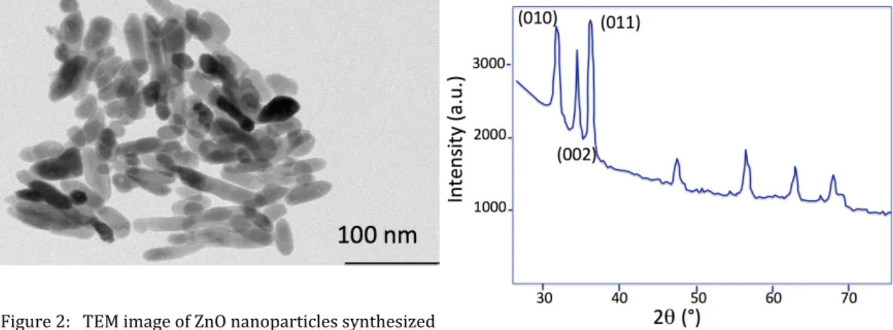
5 centrifuged 3 times with absolute ethanol [28,29]. The obtained NPs were cylinder-shaped with and average particle size of about 30 nm (Fig. 2). A 200 nm-thick sample was prepared and characterized by XRD. As shown in Figure 3, we observe clearly a hexagonal crystal system for ZnO NPs, as described in the literature.
Fabrication of OSCs: For the fabrication of OSCs, a 30 nm-thick layer of ZnO film on treated
FTO (sheet resistance = 15 ohm/square,2x2 cm2) was spin-coated onto FTO at 6000 rpm for 30
s and then annealed at 100 °C for 5 min. The ZnO layer is treated with a RCA mixture (H2O2;NH3;H2O in a ratio of 1/1/1600 v/v) at 80 °C for 10 min. The adsorption of SAMs on ZnO
from CH2Cl2 solutions (5.10-4 M) was accomplished by dipping the sample for 2 hours. The
blend solution of P3HT (Donor) –PCBM (acceptor) was dissolved in dichlorobenzene at a concentration of 25 mg/ml (1:1) and was spin-coated at 1500 rpm for 60 s on FTO. The typical thickness of the active layer was 150 nm. Before the final coating with PEDOT:PSS/Au, the active layer was thermally annealed at 150 °C for 20 min. Finally a 100 nm-thick Au electrode was vacuum-deposited at 2×10⁻⁴ Pa on top of the spin-coated PEDOT:PSS through a shadow
mask. The active pixels obtained have an area of approximately 0.2 cm2.
Measurements: The orientation of the two grafted molecules , F-A and CH3O-A, deposited on
ZnO/Au were characterized by Polarization Modulation-Infrared Reflection-Absorption Spectroscopy (PM-IRRAS) measurements using a Nicolet 8700 spectrometer (sum of 2000 scans, 4 cm−1 resolution, and 0.47 cm−1 optical velocity) along with a photoelastic modulator
PEM-90 (Hind Instruments). To obtain the selection rule, ZnO was deposited on flat Au substrates. Figure 2: TEM image of ZnO nanoparticles synthesized by polyol way Figure 3: XRD pattern of ZnO NP with hexagonal crystal system α=β=90°; γ=120° a=b≠c
6
The surface energy (γ) of the ZnO layer before and after SAM treatment was evaluated by measurement of the static advancing contact angle with deionized water and diiodomethane. The contact angles (Kruss, Model DSA 25) were entered into the Wu model (harmonic mean) for the calculation of the dispersive and polar components of the surface energy. Current density-Potential (J-V) measurements under illumination (65 mW/cm2) by a Xe lamp (150 W)
with a 1.5 G filter were performed using a Keithley model 2400 source measure unit.
Quantum chemical calculations: The optimizations and analytical frequency calculations
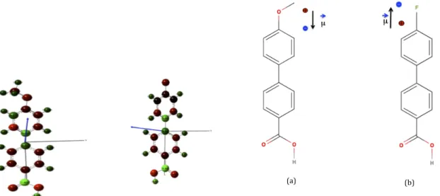
were conducted by using density functional theory (DFT) at B3LYP/6-31+G* level of theory as implemented in Gaussian09 [30]. The corresponding infrared absorption spectra have been simulated from calculated frequencies with the recommended uniform scaling factor of 0.9614 [31]. The values of dipole moments of CH3O-PP-COOH and of F-PP-COOH along the z-axis are 2.94 D and 0.15 D. (Fig.4) . The values of dipole moments of CH3O-PP-COOH and of F-PP-COOH along the z-axis are 2.94 D and 0.15 D. (Fig.4)
3. Grafting and structure of the dipolar SAMs onto ZnO layer
We used two different molecules Y-PP-COOH (Y = F, OCH3) bearing an electron-withdrawing (Y = F) or donating (Y = OCH3) substituent. As shown in Figure 5, the dipole moment of grafted molecules assembled in a monolayer is a priori expected to point towards the substrate for CH3O-PP-COOH (CH3O-A) whereas that for F-PP-COOH (F-A) points towards the bulk of the active layer.
Figure 4: calculation of dipolar moment of CH3 O-PP-COOH and F-PP-COOH (a) (b) Figure 5. Chemical structures: (a) CH3O-A; (b) F-A and the dipole induced by the terminal moiety.
7 Table 1. Assignment and wavenumbers of the main bands for F-A and CH3O-A in KBr, grafted onto ZnO NPs/Au in KBr, and calculated values.
3.1. Characterization by infrared spectroscopy
3.1.1. Assignment of bands by the DFT method In a first step, we are interested in indexing the IR bands of CH3O-A and F-A in KBr pellets. This attribution was determined with the help of calculated frequencies.
For CH3O-A the calculated bands were assigned as follows: the carboxylic acid band COOH at1716 cm-1; the band at 1589 cm-1 corresponds to the band of L-polarized phenyl (ν1); the band
of the M-polarized phenyl (ν2) is at 1538 cm-1. In the low wavenumber region, the band at 813
cm-1 was assigned to the C-H out-of-plane vibration (N-polarized) (Table 1, Fig. 6-7). Vibrations and their polarization (L, M, N) molecule grafted onto ZnO/Au; PM-IRRAS (cm-1) F-A CH3O-A molecule grafted on ZnO NP in KBr (cm-1) F-A CH3O-A Molecule in KBr (cm-1) F-A CH3O-A Cal. Exp. Cal. Exp. ν(C=OOH) 1719 1689 1716 1681 ν (COO-)as 1542 1545 1540 1549 ν(COO-)s 1424 1426 1431 1425 Phenyl ν1, (L) 1605 1606 1603 1606 1596 1609 1589 1599 Phenyl ν2, (M) 1525 1525 1526 1545 1525 1538 1530 ν (OC-OH) 1255 1256 1320 1328 ν (C-F) 1244 1243 1208 1240 γ(C-H) (N) 833 831 834 831 815 824 813 831
8 Similarly, for F-A the attributions of the bands can be determined. For high wavenumbers, the band at 1719 cm-1 was assigned to the carboxylic acid band COOH. For the phenyl bands, the
first band ν1 (C=C) located at 1596 cm-1 is L-polarized and the second, ν2 (C=C), at 1545 cm-1 is
M-polarized. The out-of-plane vibration C-H band of the biphenyl moiety at 810 cm-1 is
N-polarized .
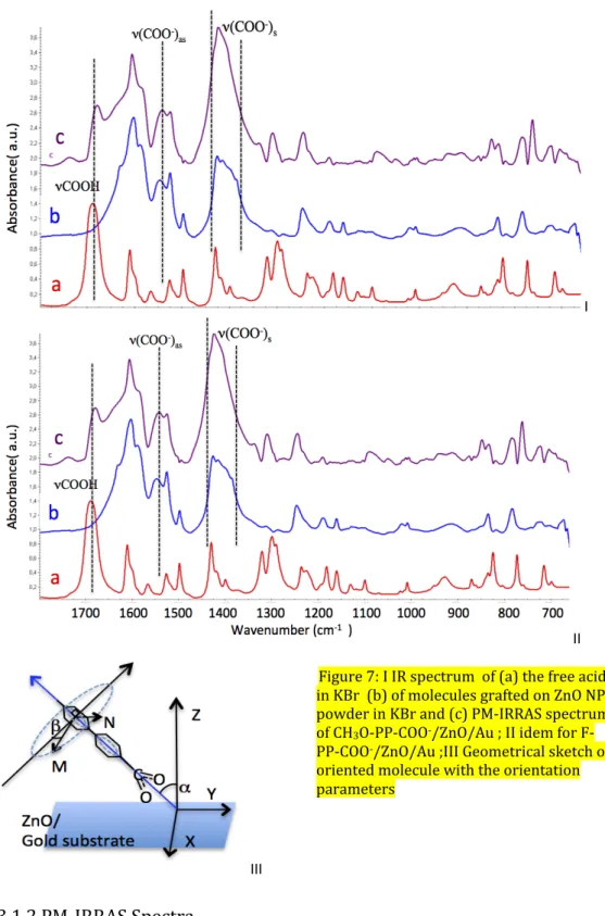
Figure 6. Polarization axis L, M, N or direction of the possible transition dipolar moment of the Y- PP-COOH molecule (Y not represented )
9 3.1.2 PM-IRRAS Spectra
In order to obtain the relative intensities of the dipolar transition moments of the grafted molecules and thus the molecular orientation, we determined the IR spectra of the molecules grafted isotropically onto a powder of ZnO nanoparticles.
Figure 7.I compares the PM-IRRAS spectra of CH3O-PP-COOH /ZnO film deposited on a gold
substrate with the IR absorption spectra of the molecules free or grafted onto ZnO NPs, both in I II III Figure 7: I IR spectrum of (a) the free acid in KBr (b) of molecules grafted on ZnO NPs powder in KBr and (c) PM-IRRAS spectrum of CH3O-PP-COO-
/ZnO/Au ; II idem for F-PP-COO-/ZnO/Au ;III Geometrical sketch of
oriented molecule with the orientation parameters
10 KBr. We deduce that the molecules are grafted onto the ZnO surface, since the band assigned to COOH at 1681 cm-1 is no longer present in either spectrum of the molecules with ZnO. The acid function has evolved into a carboxylate anion bound to the Zn(II) cation, which gives two new bands. A broad symmetric one, ν (COO-), at 1426 cm-1 (1425 cm-1 for ZnO NPs), polarized along
the bisectrix of the OCO angle, and a weak asymmetric one at 1545 cm-1 (1549 cm-1 for ZnO
NPs), polarized perpendicularly to the previous band.
The ν1(C=C) biphenyl band is blue-shifted from 1599 cm-1 to 1606 cm-1 and the biphenyl
ν2(C=C) band red-shifted from 1530 to 1527 cm-1 (1526 cm-1 for ZnO NPs ) (Table1).
The main vibration modes of CH3O-A in a KBr pellet are reported in Table 1 and compared to
DFT values computed at the B3LYP/6-31+G* level. The frequencies differ by 0-10 cm-1.
The nature of the chemisorption of a carboxylic acid on a metal oxide strongly depends on the difference Δ(νCOO-) = ν(COO-)as - ν(COO-)s [32,33]. The value of Δ(νCOO-) = 120 cm-1 indicates
that grafting occurs by bidentate bridging with two oxygen atoms bonded symmetrically to two Zn2+ atoms.
The PM-IRRAS spectra of F-PP-COO-/ZnO/Au (Fig.7 II) shows that F-A has been successfully
grafted onto the ZnO surface, since the band assigned to ν(COOH) at 1689 cm-1 has
disappeared. There is a weak asymmetric band ν(COO-) at 1542 cm-1. The ν1(C=C) band of
biphenyl is red-shifted from 1609 to 1605 cm-1 (1603 cm-1 for ZnO NPs) while the ν2(C=C) band
of biphenyl at 1525 cm-1 does not move. Similarly, for F-A the experimental wavenumbers are lower than the theoretical ones by ca. 10-25 cm -1 (Table 1). The value of Δ(νCOO-) = 118 cm-1 is consistent with grafting again involving bidentate bridging with two oxygen atoms bonded symmetrically to two Zn2+ atoms. 3.1.3 Molecular orientation Using the relative absorbance ratio of the transition bands in the SAM/ZnO (I(L1607)/I(M1528))
and (I(M1528)/I(N830)), and by comparison with those corresponding to molecules in KBr
(A(L1607)/A(M1528)) and (A(M1528)/A(N830)), we can estimate the orientation of the two
molecules as follows. By using the selection rule for a metallic substrate we get:
11
Where M is the transition dipolar moment, and E is the electrical field perpendicular to the metallic gold substrate. Let us point out that the computed angle of inclination with respect to the normal to the surface of gold is overestimated compared to the real angle, with the local normal towards the not fully flat surface of ZnO NP that is concerned by the variation of the work function. From equation (1) we can determine the tilt and twist angles, α and β, respectively (Fig. 7.III, table 2), by the following equations [34]: (2) For CH3O-A, in order to measure correctly the angles of orientation, the M and L bands were deconvolved . Molecules Angles CH3O-A F-A α(°)(±5) 56 26 β(°)(±5) 41 46
Table 2: Estimation of the orientation angles of the molecules (SAMs) ; the tilt angle is here slightly overestimated (see text). According to the IR spectra, the tilt angle of F-A is smaller than that of CH3O-A. Since the tilt angle determines the effect of the dipole and the variation of the work function, we can infer that the effect of the dipole of F-A is enhanced relatively to CH3O-A.
3.2. Characterization
by
contact
angle
measurements:
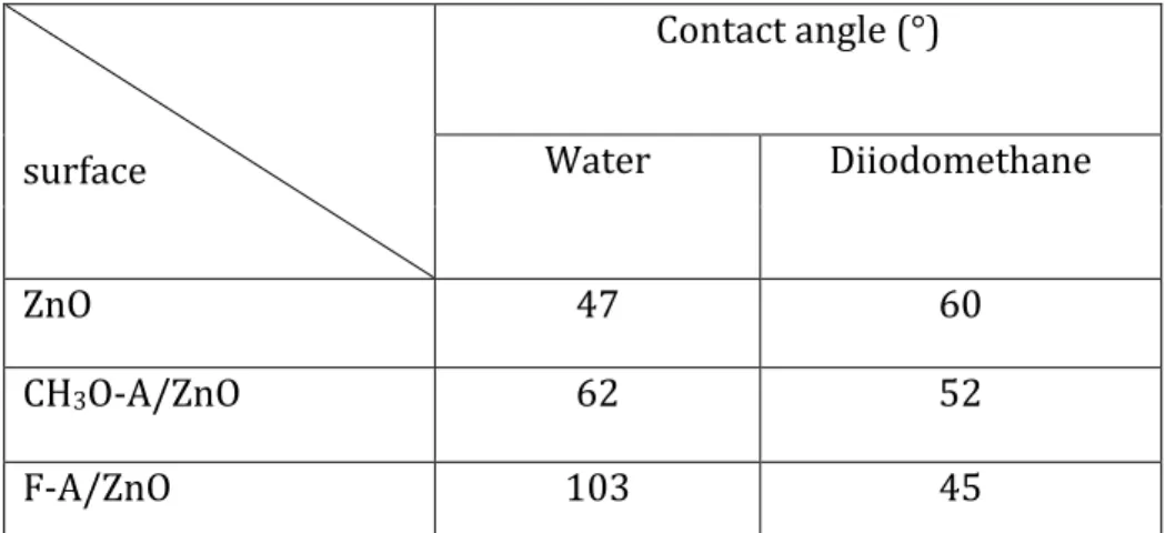
Determination of surface and adhesion energy
The outermost part of the SAMs/ZnO layers is chemically important since it determines the way of growth and organization of the photoactive P3HT-PCBM blend. We have probed this by measuring the wetting of the SAMs and their adhesion energy with organic SC. For the F-A/ZnO
12 sample, the contact angle reaches a maximum value of 103°, which shows that the layers are well organized (Table 3). This result is similar to that found in the literature for a hydrophobic molecule with fluorine [27]. Table 3: Measurement of the contact angle of ZnO and of different SAM-modified ZnO surfaces.
Surface energy values were derived from the contact angles. The surface energy (γ) components are calculated according to the method of van Oss, Good and Chaudhury [35]. We determined the adhesion energy (WZnO-M) of ZnO modified with P3HT et PCBM, considering
that it consists of two components resulting from dispersive (WdZnO-M) and polar (WpZnO-M) interactions (M = P3HT or PCBM).Thus, WZnO-M is considered as the sum of two terms:
;
The two components resulting from dispersive (γdM) and polar (γpM) interactions to the surface energies of P3HT and PCBM are determined from the literature [36]. The physicochemical properties of the groups F and CH3O, and the differences in orientation, result in a lower polar component of the surface energy for the former than for the latter, 0.4 and 8 J/m2, respectively, while the dispersive components are similar (Table 4). d p
ZnO-M ZnO-M ZnO-M
W
=W
+
W
WZnO-Mp = 2 γZnO p .γ M p ZnO-M Wd 2 d . d ZnO M γ γ = ZnO-M W 2( d. d p . p ) M ZnO ZnO M γ γ γ γ = + surface Contact angle (°) Water Diiodomethane ZnO 47 60 CH3O-A/ZnO 62 52 F-A/ZnO 103 4513
The adhesion energies of P3HT with CH3O-A/ZnO (78 J/m2) and bare ZnO (79 J/m2) are close
but larger than those for F-A/ZnO (70 J/m2). Identically, PCBM also interacts the most with
CH3OSAM (106 J/m2) and ZnO (111 J/m2). On the other hand, the FSAM surface appears the
less interacting and in this case , the interactions of P3HT and PCBM are both optimum with PCBM , 72 J/m2 and 100 J/m2 respectively with however strongest PCBM-PCBM interactions. Clearly , CH3 OSAM and bare ZnO interact more strongly with the photoactive molecules than F-A. Sample Surface enery (J/m2) Energy of cohesion or adhesion (J/m2) with P3HT PCBM Strongest interaction of the blend P3HT and PCBM components when in contact with the three surfaces (J/m2) Total Dispersive Polar P3HT 26.9 24.6 2.3 54 72 PCBM 50.2 39.8 10 72 100 ZnO 62 45 17 79 111 P3HT-ZnO 79 PCBM-ZnO 111 CH3OSAM/ ZnO 57 49 8 78 106 P3HT-CH3OSAM 78 PCBM-CH3OSAM 106 FSAM/ZnO 47 46.6 0.4 70 90 P3HT-PCBM 72 PCBM-PCBM 100 Table 4: Measurement of the surface, adhesion and interaction energies. Comparing the two SAMs , we expect that with CH3OSAM , the surface interactions drive the first step of the deposition whereas with FSAM , the interactions in solution are predominant . Another consequence with the fluorinated SAM is the higher mobility of the weakly adsorbed photoactive molecules; this mobility may promote the aggregation notably of PCBM at the
14
FSAM surface . On the other hand , the methoxy SAM may ensure an initial random distribution of adsorbed interpenetrated photoactive molecules .
It appears difficult at this stage to establish a clear relationship between the interactions at the surface and the structuration of the heterolayers . We expect at least some differences in the organization and interpenetrations of P3HT and PCBM phases [37].
Let us point out that the films observed with binocular magnifiers, are a little more homogeneous with the CH3OSAM than with FSAM as may be expected from previous consideration. This point will be clarified thanks to the electrical analysis below .
4. Electrical characterization of the photovoltaic cells
Figure 8 shows the current density versus applied voltage J-V characteristic in the dark for the FTO/ZnO/P3HT-PCBM/PEDOT/Au cells, the ZnO being treated by SAMs or not. These characteristics show a rectifying character except for F-A/ZnO. The current through the samples is quite high (of the order of mA/cm2). For CH3O-A, the dipole a priori oriented (- +)from the ZnO towards the active film (m < 0) lowers the work function of the ZnO, so the
difference between the LUMO of the PCBM (Acceptor) and the conduction band of the ZnO decreases, leading to an improvement in the internal field and to the rectifying effect. For F-A grafted onto ZnO, the dipole oriented (+ -) from the ZnO towards the active film (µ> 0), leads to a significant increase in the work function of the ZnO and contributes to the reduction of the built-in field. This accounts for the quasi-symmetrical behavior of the I-V curve in the dark (see 4.2) Figure 8 : Current density-voltage J-V curves of inverted OSCs in the dark: (a) ZnO; (b) CH3OSAM/ZnO; (c) FSAM/ZnO
15
4.1. Photoelectric parameters of the cells
The J-V curves (Fig. 9) recorded under white light illumination confirm the diode-like photovoltaic behavior of our samples with significant rectification, together with a short-circuit current density of the order of some mA/cm2 and an open-circuit voltage varying between 0.19
and 0.5 V for all ZnO samples. As shown in Table 5, the values of the open-circuit voltage of the cells with F-A/ZnO, ZnO and CH3O-A/ZnO are 0.19, 0.39 and 0.50 V, respectively. The structure
with CH3O-A shows the best value of Voc. On the contrary, for F-A, the value of Voc is much lower
than that for bare ZnO. The improvement of the Voc for CH3O-A and noticeable reduction for F-A
would suggest a priori a significant dipole effect (see Discussion).
The values of the short-circuit current density (Jsc) of the cells with F-A, ZnO and CH3O-A are
5.8, 8.7 and 9 mA/cm2, respectively. The structure with CH3O-A has a Jsc very similar to that of
bare ZnO. On the other hand, the Jsc value for F-A is lower than for untreated samples.
The shapes of the J-V curves are strongly affected by the SAMs. Notably a low value of the fill-factor (FF) of the cell is obtained with F-A/ZnO (27%) whereas bare ZnO and CH3O-A/ZnO
have FF values of 35% and 45%, respectively. Figure 9: Current density-voltage J-V curves of inverted OSCs under AM 1.5 G simulated illumination with an intensity of 65 mW/cm2: (a) ZnO; (b) CH3OSAM/ZnO; (c)
FSAM/ZnO. Inset : zoom on the area of photovoltaic interest
16 Sample Voc(V) Jsc (mA/cm2)
FF(%) PCE(%) rsep= JLmax/Jph,sat
(%) Rp(Ω.cm 2) R s(Ω. cm2) ZnO 0.39 8.7 35 (s*) 1.8 49 168 30 CH3 O-A/ZnO 0.50 9 45 3.1 54 324 20 F-A/ZnO 0.19 5.8 27 (s*) 0.45 27 46 29 Table 5: Photovoltaic parameters for cells with and without SAM; (s*: s-shaped curve).
Another striking feature in the I-V curves for bare ZnO and F-A/ZnO under illumination is their s-shaped form. In the first case, this behavior is most likely a direct consequence of the phenomenon of recombination of free charges or of a charge transfer complex at the surface states of ZnO [38]. The holes created at this interface can recombine easily with the electrons via the surface states of ZnO and this induces the s-shaped behavior and therefore a lower FF. These surface states, often associated with pendant links, are suppressed by the presence of a SAM. This phenomenon should in principle also intervene with F-A, but this is clearly not the case. This unexpected behavior may result from the negatively charged plane containing the fluorine, which attracts the minority carriers (holes) towards the ZnO layer and then increases hole-electron recombination.
The PCE values for cells with F-A/ZnO, bare ZnO and CH3O-A/ZnO are 0.4, 1.8 and 3.1%,
respectively. The best performance is obtained understandably with CH3O-A/ZnO. The
fluorinated SAM leads to a much lower value than bare ZnO. These solar cells present a PCE twice as large with an adequate SAM. The PCE are comparable to those found in the literature
17
Low values of parallel resistance RP (or shunt resistance), obtained from the inverse of the
slope of the J-V curve at Jsc, account for a large leakage current independent of
photoabsorption. We observe a large difference of RP between CH3
O-A/ZnO, bare ZnO and F-A/ZnO cells, which have the following values, 330, 170 and 50 Ω.cm2, respectively. The best
and largest RP value is obtained with CH3O-A/ZnO, 50% greater than for bare ZnO, which is
itself 400% higher than that for F-A/ZnO. For the latter the smaller RP involves a large leakage
current (Table 5).
The values of the series resistance, Rs, which is the inverse of the slope of J-V curve at Jsc and
accounts for the resistance of the contacts, are similar for the SAM-based cells and greater than for bare ZnO (30 Ω.cm2).
4.2. Analysis of results
The value of Voc improves on going from bare ZnO and CH3O-A/ZnO-based cells (from 0.39 to
0.50 V), whereas the Jsc values are the same and the Rp values are comparable. Voc varies
independently of the current density Jsc and only accounts for the energy shift at the
ZnO/P3HT-PCBM interface. Clearly the presence of the dipolar CH3O-A diminishes the work
function of ZnO and increases Voc (see below). The bulk microstructure of the P3HT-PCBM blend affects the Jsc. We deduce that bare ZnO and CH3O-A/ZnO induce similar microstructuration of the blend [41-43]. Figure 10: Energy level diagram of the devices with SAM-modified ZnO.
18 On the other hand, F-A decreases Voc (δVoc = -0.2 V), Jsc (ΔJsc/Jsc = -35%) and Rp (ΔRp/Rp = -75%)
compared to bare ZnO. In this case, the SAM has an effect not only on the reduction of Voc but
also negatively affects the microstructure blend.
To analyze the issue of the effect on blend morphology, we consider (i) the neat photocurrent density (Jph), which is expressed by the difference between the currents under illumination (JL )
and in the dark JD (Jph = JL −JD) and (ii) JLmax which is the current density at the point of
maximum power . Jph reaches a plateau with a saturation current density Jph,sat. According to
[41], the a relevant parameter with respect to a good phase separation is the value of the ratio rsep = JLmax/Jph,sat.. As observed from Table 5, rsep reaches similar values of 49% and 54% with
ZnO and CH3O-A/ZnO whereas the ratio falls to 27% with F-A/ZnO.
Thereby we expect a large difference of phase segregation and interpenetration of the blend as suggested above (see 3.2) i.e. a good phase separation in the first cases and in the second case of the fluorinated molecule, large-scale heterogeneities and too large domains to lead efficient exciton dissociation .
Therefore, the increase of Voc observed with CH3O-A/ZnO can be attributed to a dipole effect.
Conversely, the Voc drop from 0.39 to 0.19 V with F-A/ ZnO can not only be attributed to such
an electrostatic effect of the SAM, but also reflects a variation of the structural order of the active mixture developed on the SAM having low surface energy. This unfavorable structuration, with domains bigger than the diffusion length in the case of F-A, which limits the exciton dissociation at the P3HT-PCBM interface and increases the recombination probability, has been pointed out previously [42].
4.3. Semi-Quantitative meaning of the dipole effect
For CH3O-A, the dipole oriented (- +) from the ZnO towards the active film (µM < 0) lowers the
work function of the ZnO, so the difference between the LUMO of the PCBM and the conduction band of the ZnO decreases, leading to an improvement in the internal field and an increase in Voc respectively [43, 44]: (+0.11 V) (10. 9). This also accounts for the increase in conversion efficiency from 1.2% to 2%. For F-A grafted onto ZnO, the dipole µM, oriented (+ -) from the ZnO towards the active film (> 0), leads to a significant increase in the work function of the ZnO and contributes to the reduction of Voc (-0.2 V) .
The maximum Voc is generally expressed as the difference between the HOMO of the donor and
19 those of the active molecules decreases Voc. The open-circuit voltage is given by the following
equation, which takes into account the density of charges gPEDOT and gZnO photogenerated at the
anode and the cathode, respectively [45]: (3) where the potential energy shift ΔΦ due to a dipolar SAM layer (μM) at the ZnO surface is given by [46]:
∆∅ =
!!!! !!!!(4) Here Γ is the surface density of SAM molecules, which may depend on the nature of the grafted molecule, e (> 0) the elementary charge, µM the dipole moment of the adsorbed molecule
considered as positive when it is directed (+ -) from FTO/ZnO to PEDOT/Au, ε0 is the vacuum
permittivity and εr the static dielectric constant of the SAM layer.
In our previous work [45], we took into account photogeneration at the anode and cathode interfaces, since the structure was far from a BHJ. However, in the present case one can assume that the main photogeneration process takes place in the bulk, far from the electrode interfaces, which leads to the neglect of the latter term in equation (3); the open-circuit voltage can then be expressed by the following equation :
(5)
Considering the work functions of ZnO and PEDOT:PSS as 4.0±0.1 and 4.33±0.1 eV, respectively, we note that our experimental value of Voc = 0.39 V is slightly greater than that
derived from the difference between the work functions of the electrodes (0.33 ± 0.2 V), which is: 1/e (
ϕ
PEDOT-ϕ
ZnO)≥0.39±0.1V. Indeed, the work function of ZnO, WZnO, should be reducedby 0-0.06 eV, i.e. it is between 4 and 3.94 eV.
4.4. Estimation of the grafting dipole
The best Voc was obtained with CH3O-PP-COOH. The difficulty in applying equation (2) comes
from the lack of knowledge of
∆∅ or of
the dipole moment of the grafted molecule. Indeed, the overall dipole implies several components. The first is due to the neutral moiety with the
(
)
(
)
PEDOT oc PEDOT ZnO ZnO g 1 kT V = - ln e e g ⎛ ⎞ φ − φ + Δφ ⎜ ⎟ ⎝ ⎠(
)
(
)
oc PEDOT ZnO 1 V = e φ − φ + Δφ
20
methoxy group and the second is induced by the grafting and formation of (COO-, ZnOH + or
COOδ-_ZnOH δ+).
Cornil et al. have extensively addressed this calculation with a grafted SAM, Y-P-COOH/ZnO (Y = CH3O, H, CN) [47]. They decompose the variation of the total work function for bare ZnO,
δWDFT(eV), into three components related to: i) the core of the molecule (or its radical F-A.); ii)
the ZnO modification (rZnO), and iii) bond-dipole potential (BD): δWDFT(SAM)= δWrYPCOO. +δWrZnO +δWBD (6a)
The rZnO part is weak and does not depend on Y (± 0.05 eV) and very little on the grafting mode. The BD part is rather important but depends a few on Y . Then for a set of molecules having the same grafting mode, we may expect :
δWDFT(SAM) ≈ δWrYPCOO. + constant (6b)
Figure 11 shows the total variation of the work function of the ZnO grafted molecules, d WDFT(eV ), as a function of the calculated (eq. 7) work function for the neutral SAM (nSAM) or
a physisorbed one , δWnYPCOOH. This curve appears linear with a slope of 0.99 with an
attenuation of the effect of the dipole of the neutral molecule on δ WDFT due to the grafting on ZnO. This should reflect the validity of equation 6b. A similar model has been evaluated and compared with experimental data obtained by UPS or Kelvin probe [48]. Figure 11: Variation of the work function δWDFT of acid molecules grafted onto ZnO via BM2-2 mode (bidentate) as a function of that of the neutral acids deduced from their dipole moment μM (Debye) (eq. 7) ; see text and [47]
21 Concerning F-A and CH3O-A molecules, the same bidentate grafting is supported by the fact that the difference in wavenumbers, νCOO-(as)-νCOO-(s), is equal for the two molecules (118
cm-1 for FA and 117 cm-1 for CH3O-A). Given the similarity between the monophenyl
molecules with biphenyl ones and notably assuming an identical grafting , we may apply the quasi-linear relation between δWDFT = f (δWnYPPCOOH ), for the grafted SAM of CH3O-A.
we have :
δWnSAM(eV ) = δV(volt) =ΓnSAM *μM * cos (α)*3,77 10-19 / εnSAM (7)
δWnCH3OA = -0.58 eV
the calculated dipole μM by DFT is -2.94D; ΓnSAM is the density of molecules estimated via the
area projected on the surface, a the tilt angle already calculated by IR , εnSAM is the static
dielectric constant of the nSAM , estimated at 4.2; the latter is estimated by the calculated dipole moment of the radical CH3O-P. (5.7 D) and δWrCH3OP. found in Cornil et al. The surface
densities of two molecules were estimated by modeling the molecules in blocks:
𝛤!"#!!!!= 3,95 10!"𝑚𝑜𝑙/𝑐𝑚! and 𝛤
!"!! = 4.2 10!"𝑚𝑜𝑙/𝑐𝑚!.
For the F-A molecule with its dipole of -0.15D, we obtain δWnF-A = -0.054 eV using the previous
relation (εnFA = 4, α = 26 °) (table 6). From the curve in fig. 11, we get by extrapolation the
δWDFT values of -0.41 and 0.11V for the two grafted SAMs . Dipole moment of neutral molecules (Debye) δWnSAM (eV) δWDFT, (SAM) (eV) δVoc eff (in presence of PCBM) (V) δVoc (SAM-ZnO) (exp.) (V) δVoc (SAM- .ZnO)- δVoc .eff (V) ZnO 0 0 0 CH3O-A -2.94 -0.58 -0.41 ≥0.13 0.11 -0.02 F-A -0.15 -0.053 0.11 -0.11 -0.20 -0.09
Table 6: Comparison of theoretical and experimental Voc values for bare ZnO and
SAM-modified ZnO.
22 Indeed, the value of -δWDFT(CH3O-A) is larger than the difference between the Conduction Band (CB) of ZnO and the LUMO of PCBM (3.7 eV), which is an unusual case, rarely treated in the literature. A dipolar effect of around 0.3 eV (or 0.3 V), i.e. equal to the difference between the CB of the ZnO and the LUMO of the PCBM (WLUMO PCBM), would be ideal to obtain the alignment
between the levels of ZnO (WCBZNO) and PCBM. An excessive dipolar effect should induce
electron transfer from ZnO to the LUMO of PCBM provided that the ZnO is sufficiently doped. This restores the energetic equilibrium and the electronic structure of the PCBM with respect to ZnO.
The relative positions of the CBZnO and the LUMOPCBM determine whether there is an extraction
barrier or not. An extraction barrier expected here with undoped ZnO (necessarily less than 0.14 eV) should induce carrier recombination and therefore a decrease in Voc. Clearly, this loss
of potential cannot be higher than 0.14 V relative to the ideal alignment (loss = 0) and we expect for the effective value of δVoc in presence of PCBM:
δVoc,eff (CH3O-A)(V) ≥ 2(WCBZNO -WLUMO PCBM)+δWDFT(CH3O) (V) = 0.13 V (see fig.12)
We note that the estimated value of 0.13 V obtained with CH3O-A is quite close to the
experimental value, suggesting that the dipole effect accounts for the value of Voc. In the case of
F-A, the experimental variation of |Voc| relative to bare ZnO is higher than the semi-calculated
value (|-0.11 V|). The effect of F-A seems to be more damaging than expected for the dipole effect alone. This confirms that another effect is involved in the loss of performance of the devices with F-A. As shown before, the poor performance of the OSC, i.e. the decrease in Jsc,
JLmax/Jph,sat and PCE, has been observed and accounted for by the nature of the microstructuring.
Consequently, the impact of F-A is not entirely due to a dipole electrostatic effect.
In conclusion, the dipolar effect of CH3O-A has been evidenced semi-quantitatively and is
related mainly to the improvement of Voc. The SAM has no significant influence on Jsc and thus
on the structure of the photoactive film. On the other hand, the lowering of Jsc, Voc and the overall
performance of the PV cell observed with F-A are accounted for by the dipole effect and the nanostructuration of the photoactive film.
23
5. Conclusion
The modification of ZnO by two SAMs, CH3OSAM and FSAM, reveals large differences in the
interface properties, active film structuration and overall PV performance of the cells. However, the influence of the SAM is very dependent on its nature, orientation, and wettability. When ZnO is treated with CH3O-A, the cell Voc improves and the total PCE is twice as high as for
bare ZnO. On the other hand, FSAM decreases both Voc , Jsc and the PCE, which is reduced by a
factor of four with respect to bare ZnO. Comparison of the features of CH3OSAM and FSAM
allows us to clearly distinguish two possible effects: (i) on the work function of ZnO via the dipole; (ii) on the P3HT-PCBM blend microstructure.
In the case of CH3OSAM, the effect of the calculated dipole on the variation of the ZnO working
function - even with a weakly defined molecule orientation - is large and even greater than the difference between the electronic levels of the LUMOPCBM and the CBZnO. The Voc is better than
with the bare ZnO. The wetting of CH3OSAM and its adhesion with the blend are quite similar to
those of bare ZnO, and in the same way, the current densities are very close. Consequently, the microstructurations are also quite similar and the SAM dipole effect only is important on Voc.
The well-oriented FSAM, with its inverted dipole compared to CH3OSAM, negatively affects the
variation of the work function of the oxide. However, Voc and Jsc are both reduced. The
inadequate microstructuring of the photoactive mixture, due to the poor wetting of the FSAM, and the weakness of its interaction with the blend components , is also involved in the poor overall performance of the OPV cell.
Figure 12. Effect of the two SAMs on the displacement of conduction band of ZnO towards the LUMO of PCBM and on the variation of VOC relatively to bare ZnO
24 Acknowledgments:
We thank very much Pr. Antoine Kahn for his remarks and the stimulated discussions. Similarly, we are grateful to Dr. John Lomas (CNRS DR) for his proofreading and text enhancements. Quantum chemical calculations were performed using HPC resources from GENCI- [CCRT/CINES/IDRIS] (Grant 2019[A0080807006]).
References
[1] C. J. Brabec, N. S. Sariciftci, J. C. Hummelen, Plastic Solar Cells, Adv. Funct. Mater, 11(1) (2001) 15−26.
[2] J. Y. Kim, K. Lee, N. E. Coates, D. Moses, T. Q. Nguyen, M. Dante, A. J. Heeger, Efficient tandem polymer solar cells fabricated by all-solution processing, Science, 317 (5835) (2007) 222–225.
[3] R. H. Friend, R. W. Gymer, A. B. Holmes, J. H. Burroughes, R. N. Marks, C. Taliani, D. Bradley, D. A. Dos Santos, J. L. Bredas, M. Lögdlund, W. R. Salaneck, Electroluminescence in conjugated polymers, Nature, 397 (6715) (1999) 121−128.
[4] S. E. Shaheen, C. J. Barbec, N. S. Sariciftci, 2.5% Efficient Organic Plastic Solar Cells, Appl. Phys. Lett. 78, (6) (2001) 841−843.
[5] G . Li, V. Shrotriya, J. S. Huang, Y. Yao, T. Moriarty, K. Emery, Y. Yang, High-efficiency solution processable polymer photovoltaic cells by self-organization of polymer blends, Nature Materials 4(11) (2005) 864-868.
[6] W. Ma, C. Yang, X. Gong, K. Lee, A. J. Heeger, Thermally Stable, Efficient Polymer Solar Cells with Nanoscale Control of the Interpenetrating Network Morphology, Adv. Funct. Mater, 15(10) (2005) 1617 – 1622.
[7] J. Peet, J. Y. Kim, N. E. Coates, W. L. Ma, D. Moses, A. J. Heeger, G. C. Bazan, Efficiency enhancement in low-bandgap polymer solar cells by processing with alkane dithiols, Nat. Mater, 6(7) (2007) 497-500.
[8] W. Y. Wong, X. Z. Wang, Z. He, A. B. Djurisic, C. T. Yip, K. Y. Cheung, H. Wang, C. S. K. Mak, W. K. Chan, Metallated conjugated polymers as a new avenue towards high-efficiency polymer solar cells, Nat. Mater, 6 (7) (2007) 521–527.
25 [9] F. C Krebs, Polymer solar cell modules prepared using roll-to-roll methods: Knife-over-edge coating, slot-die coating and screen printing, Sol. Energy Mater. Sol. Cells, 93 (4) (2009) 465−475. [10] S.I. Nia , S. S. Kim, S. S. Kwon, J. Jo, J. Kim, T. Lee, D. Y. Kim, Surface relief gratings on poly (3-hexylthiophene) and fullerene blends for efficient organic solar cells, Appl. Phys. Lett, 91 (17) (2007) 173509.
[11] F.Liu, Y. Gu, J. W. Jung, W.Ho Jo,T. P. Russell, On the Morphology of Polymer-Based Photovoltaics J. Polymer Science B : Polymer phys. 50 (2012) 1018–1044
[12] P. Kohn, Z. Rong, K. H. Scherer, A. Sepe, M. Sommer, P. Müller-Buschbaum, R. H. Friend, U. Steiner, S. Hüttner, Crystallization-Induced 10-nm Structure Formation in P3HT/PCBM Blends, Macromolecules, 46, (2013)4002−4013
[13] F. Zhang, M. Ceder, O. Inganäs, Enhancing the Photovoltage of Polymer Solar Cells by Using a Modified Cathode, Adv. Mater, 19 (14) (2007) 1835−1838.
[14] H. Choi, J. S. Park, E. Jeong, G. W. Kim, B. R. Lee, S. O. Kim, M. H. Song, H. Y. Woo, J. Kim, Combination of titanium oxide and a conjugated polyelectrolyte for high-performance inverted-type organic optoelectronic devices, Adv. Mater, 23 (2011) 2759−2763.
[15] B. Wu, Z. Wu, Q. Yang, F. Zhu, T-W. Ng, C-S. Lee, S-H. Cheung, S-K. So, Improvement of Charge Collection and Performance Reproducibility in Inverted Organic Solar Cells by Suppression of ZnO Subgap States, ACS Appl. Mater. Interfaces, 8 (23) (2016) 14717−14724.
[16] Z. Kam, Q. Yang, X. Wang, B. Wu, F. Zhu, J. Zhang, J. Wu, Enhanced absorbance and electron collection in inverted organic solar cells: optical admittance and transient photocurrent analyses, Org. Electron, 15 (7) (2014) 1306−1311.
[17] Z. He, C. Zhong, S. Su, M. Xu, H. Wu, Y. Cao, Enhanced Power-Conversion Efficiency in Polymer Solar Cells Using an Inverted Device Structure, Nat. Photonics, 6 (9) (2012) 591−595.
[18] H. Liu, Z. Wu, J. Hu, Q. Song, B. Wu, H. Tam, Q. Yang, W. Choi, F. Zhu, Efficient and ultraviolet durable inverted organic solar cells based on an aluminum-doped zinc oxide transparent cathode, Appl. Phys. Lett, 103 (4) (2013) 043309.
[19] Y. Sun, H. Seo, C. Takacs, J. Seifter, A. J. Heeger, Inverted polymer solar cells integrated with a low-temperature-annealed sol-gel-derived ZnO Film as an electron transport layer, Adv. Mater. 23 (14) (2011) 1679−1683.
[20] S. K. Hau, H-L. Yip, N. S. Baek, J. Zou, K. O’Malley, A. K.-Y. Jen, Air-stable inverted flexible polymer solar cells using zinc oxide nanoparticles as an electron selective layer, Appl. Phys. Lett. 92 (25) (2008) 253301.
26 [21] B. A. MacLeod, B. J. Tremolet de Villers, Ph. Schulz, P. F. Ndione, H. Kim, A. J. Giordano, K. Zhu, S. R. Marder, S. Graham, J. J. Berry, A. Kahn, D. C. Olson, Stability of inverted organic solar cells with ZnO contact layers deposited from precursor solutions ,Energy Environ. Sci., 8 (2) (2015) 592–601.
[22] S. Alem, J. Lu, R. Movileanu, T. Kololuoma, A. Dadvand, Y. Tao., Solution-processed annealing-free ZnO nanoparticles for stable inverted organic solar cells,Org. Electronics, 15(5) (2014) 1035-1042.
[23] K. Sun, J. Ouyang ; Polymer solar cells using chlorinated indium tin oxide electrodes with high work function as the anode, Sol. Energy Mater. Sol. Cells, 96, (2012) 238-243;
[24] K Sun, B. Zhao,V. Murugesan, A.Kumar, K Zeng, J. Subbiah, W W. H. Wong, D J. Jones, J. Ouyang, High-performance polymer solar cells with a conjugated zwitterion by solution processing or thermal deposition as the electron-collection interlayer, J. Mater. Chem., 22, (2012) 24155-24165;
[25] M. J. Tan, S. Zhong, J. Li, Z. K. Chen, W. Chen, Air-Stable Efficient Inverted Polymer Solar Cells Using Solution-Processed Nanocrystalline ZnO Interfacial Layer, ACS Appl. Mater. Interfaces, 5 (2013) 4696-4701.
[26] X. Jia, Z. Jiang, X. Chen, J. Zhou, L. Pan, F. Zhu, Z. Sun, S. Huang, Highly Efficient and Air Stable Inverted Polymer Solar Cells Using LiF-Modified ITO Cathode and MoO3/AgAl Alloy Anode, ACS Appl. Mater. Interfaces, 8 (2016) 3792−3799.
[27] Ye Eun Ha, M. Y. Jo, J. Park, Y-C. Kang, S. I. Yoo, J. H. Kim, Inverted Type Polymer Solar Cells with Self-Assembled Monolayer Treated ZnO, J. Phys. Chem. C, 117 (6) (2013) 2646−2652.
[28] D. Jezequel, J. Guenot, N. Jouini, F. Fiévet, Submicrometer zinc oxide particles: Elaboration in polyol medium and morphological characteristics, Journal of Materials Research, 10 (1) (1995) 77-83.
[29] R. Brayner, R. Ferrari-Iliou, N. Brivois, S. Djediat, MF. Benedetti, F. Fiévet, Toxicological impact studies based on Escherichia coli bacteria in ultrafine ZnO nanoparticles colloidal medium, Nano Lett, 6 (4) (2006) 866-870. [30] M. J. Frisch, G. W. Trucks, H. B. Schlegel, G. E. Scuseria, M. A. Robb, J. R. Cheeseman, G. Scalmani, V. Barone, B. Mennucci, G. A. Petersson, H. Nakatsuji, M. Caricato, X. Li, H. P. Hratchian, A. F. Izmaylov, J. Bloino, G. Zheng, J. L. Sonnenberg, M. Hada, M. Ehara, K. Toyota, R. Fukuda, J. Hasegawa, M. Ishida, T. Nakajima, Y. Honda, O. Kitao, H. Nakai, T. Vreven, J. A. Montgomery, Jr., J. E. Peralta, F. Ogliaro, M. Bearpark, J. J. Heyd, E. Brothers, K. N. Kudin, V. N. Staroverov, R. Kobayashi, J. Normand, K. Raghavachari, A. Rendell, J. C. Burant, S. S. Iyengar, J.
27 Tomasi, M. Cossi, N. Rega, J. M. Millam, M. Klene, J. E. Knox, J. B. Cross, V. Bakken, C. Adamo, J. Jaramillo, R. Gomperts, R. E. Stratmann, O. Yazyev, A. J. Austin, R. Cammi, C. Pomelli, J. W. Ochterski, R. L. Martin, K. Morokuma, V. G. Zakrzewski, G. A. Voth, P. Salvador, J. J. Dannenberg, S. Dapprich, A. D. Daniels, Ö. Farkas, J. B. Foresman, J. V. Ortiz, J. Cioslowski, and D. J. Fox, Gaussian 09 (Gaussian, Inc., Wallingford CT, 2009).Gaussian, Inc., Wallingford CT (2009).
[31] C. Mihesan, M. Ziskind, C. Focsa, M. Seydou, F. Lecomte, J. P. Schermann, Structure of neat and hydrated liquid nicotine and laser resonant desorption of clusters from nicotine– water solutions, International Journal of Mass Spectrometry, 277 (1-3) (2008) 284-290.
[32] Yu-Tai Tao, Structural comparison of self-assembled monolayers of n-alkanoic acids on the surfaces of silver, copper, and aluminum, J. Am. Chem. Soc.,115 (10) (1993) 4350-4358.
[33] M. Nara, H. Torii, M. Tasumi, Correlation between the Vibrational Frequencies of the Carboxylate Group and the Types of Its Coordination to a Metal Ion: An ab Initio Molecular Orbital Study J. Phys. Chem, 100 (51) (1996) 19812-19817.
[34] H. Kim, Z. Meihui, N. Battaglini, Ph. Lang, G. Horowitz, Large enhancement of hole injection in pentacene by modification of gold with conjugated self-assembled monolayers, Org. Electron. 14, (2013),2108–2113.
[35] C. J. Van Oss, M. K. Chaudhury, R. J. Good, Interfacial Lifshitz-van der Waals and polar interactions in macroscopic systems, Chem. Rev, 88 (6) (1988) 927-941.
[36] J-H. Huang, Y-S. Hsiao, E. Richard, C-C. Chen, P. Chen, G. Li, C-W. Chu, Y. Yang, The investigation of donor-acceptor compatibility in bulk-heterojunction polymer systems, Appl. Phys. Lett, 103 (4) (2013) 043304.
[37] P. M. Beaujuge, J. M. J. Fréchet, Molecular Design and Ordering Effects in π-Functional Materials for Transistor and Solar Cell Applications, J. Am. Chem. Soc, 133 (50) (2011) 20009-20029.
[38] A. Wagenpfahl, D. Rauh, M. Binder, C. Deibel, V. Dyakonov, S-shaped current-voltage characteristics of organic solar devices, Phys. Rev. B, 82 (11-15) (2010) 115306.
[39] Y. Thaver, SO. Oseni, K. Kaviyarasu, RP. Dwivedi, GT. Mola, Metal nano-composite assisted photons harvesting in thin film organic photovoltaic, Physica B: Condensed Matter, 582(2020), 411844.
[40] A. Hazra, I. Mal, D.P. Samajdar, T.D. Das, Analytical modelling of organic solar cells with scattering interface, Optik, 168 (2018) 747-753.
[41] Y. Liu, D. Tang, Kaicheng Zhang, Peng Huang, Zhaowei Wang, Kai Zhu, Zhendong Li, Ligang Yuan, Jian Fan, Yi Zhou, Bo Song, Tuning Surface Energy of Conjugated Polymers via
28
Fluorine Substitution of Side Alkyl Chains: Influence on Phase Separation of Thin Films and Performance of Polymer, Solar Cells. ACS Omega, 2 (6) (2017) 2489−2498.
[42] W. Huang, E. Gann, L. Thomsen, A. Tadich, Yi-Bi. Cheng, Ch. R. McNeill, Metal Evaporation-Induced Degradation of Fullerene Acceptors in Polymer/Fullerene Solar Cells, ACS Appl. Mater. Interfaces, 8 (2016) 29608−29618. [43] G. G. Malliaras, J. R. Salem, P. J. Brock, and J. C. Scott, Photovoltaic measurement of the built-in potential in organic light emitting diodes and photodiodes, Journal of Applied Physics, 84 (3) (1998) 1583. [44] R. M. Hewlett, M. A. McLachlan, Surface Structure Modification of ZnO and the Impact on Electronic Properties , Adv. Mater., 28(2016) 3893–3921
[45] F. Kouki, N. Karsi, P. Lang, G. Horowitz, H. Bouchriha, Effect of self-assembled monolayers on charge carrier photogeneration in sexithiophene based diodes, Synthetic Metals 162 (19-20) (2012) 1741–1745.
[46] S. Ray, H. Cohen, R. Naaman, Liu H. &Amp; D. Waldeck, Organization-Induced Charge Redistribution in Self-Assembled Organic Monolayers on Gold J. Phys. Chem. B 29 (2005) 129. [47] D. Cornil, T. Van Regemorter, D. Beljonne, J. Cornil, Work function shifts of a zinc oxide surface upon deposition of self-assembled monolayers: a theoretical insight, Phys.Chem.Chem. Phys.16 (38) (2014) 20887. [48] H.Li, P. Winget,J.L.Bredas, Transparent Conducting Oxides of Relevance to Organic Electronics: Electronic Structures of Their Interfaces with Organic Layers Chem. Mater., 26, (2014) 631−646
29