HAL Id: hal-01156568
https://hal.archives-ouvertes.fr/hal-01156568
Submitted on 17 Nov 2015
HAL is a multi-disciplinary open access
archive for the deposit and dissemination of
sci-entific research documents, whether they are
pub-lished or not. The documents may come from
teaching and research institutions in France or
abroad, or from public or private research centers.
L’archive ouverte pluridisciplinaire HAL, est
destinée au dépôt et à la diffusion de documents
scientifiques de niveau recherche, publiés ou non,
émanant des établissements d’enseignement et de
recherche français ou étrangers, des laboratoires
publics ou privés.
3D-printed system optimizing dissolution of
hyperpolarized gaseous species for micro-sized NMR
A. Causier, G. Carret, C. Boutin, T. Berthelot, P. Berthault
To cite this version:
A. Causier, G. Carret, C. Boutin, T. Berthelot, P. Berthault. 3D-printed system optimizing dissolution
of hyperpolarized gaseous species for micro-sized NMR. Lab on a Chip, Royal Society of Chemistry,
2015, 15, pp.2049-2054. �10.1039/C5LC00193E�. �hal-01156568�
PAPER
Cite this:Lab Chip, 2015, 15, 2049
Received 16th February 2015, Accepted 17th March 2015 DOI: 10.1039/c5lc00193e www.rsc.org/loc
3D-printed system optimizing dissolution
of hyperpolarized gaseous species for
micro-sized NMR
†
A. Causier,
abG. Carret,
bC. Boutin,
bT. Berthelot
aand P. Berthault*
bDissolution of hyperpolarized species in liquids of interest for NMR is often hampered by the presence of bubbles that degrade the field homogeneity. Here a device composed of a bubble pump and a miniaturized NMR cell both fitted inside the narrow bore of an NMR magnet is built by 3D printing.129Xe
NMR experiments performed with hyperpolarized xenon reveal high and homogeneous dissolution of the gas in water.
Introduction
Today, nuclear magnetic resonance (NMR) is one of the most important modalities for molecular analysis and diagnosis. However, this technique intrinsically provides poor detection sensitivity, and recent years have seen the emergence of spin-hyperpolarization techniques designed to transiently boost nuclear magnetization, such as optical pumping of noble gases1 and para-hydrogen-induced polarization.2 The vast majority of NMR experiments involving gaseous hyper-polarized species include a dissolution step that most of the time is either manual (vigorous shaking3) or based on direct bubbling created by a peristaltic pump.4 While the first method possesses some advantages such as simplicity or for instance the choice of magnetic field during mixing for para-hydrogen-induced polarization,5it sometimes lacks reproduc-ibility and requires the use of fast NMR sequences to obtain maximal profit of the transient character of magnetization.6 The bubbling method requires a waiting delay before the start of acquisition to avoid distortion of the magnetic field experi-enced by the nuclei of the solution linked to the strong sus-ceptibility effects caused by the bubbles. In 2006, the use of hollow fibers7 was shown to be a fast and robust method to efficiently dissolve hydrophobic gases such as xenon without bubbling, by increasing the exchange surface between the gas and the solution. The derived systems were powerful,8but the gas exchangers were necessarily placed inside large bore
apparatus or outside the NMR magnet. As far as a narrow bore magnet is concerned for a better spectral resolution, a compromise has to be found to place the reservoir containing the short-lived species (para-hydrogen, hyperpolarized noble gas) outside the magnet bore while minimizing the distance to the detection region. A mixing chamber outside the magnet implies a big volume of solution and causes a polarization loss, due to the fact that the magnetic field is much lower and also that the xenon relaxation rate is higher when the gas is dissolved.
We describe here a system using a microfluidic device for continuous- or stopped-flow delivery of gas, enabling its dis-solution into a small volume as close as possible to the detec-tion region for optimized magnetic resonance spectroscopy and imaging. We have developed a compact system that can be integrated into a conventional narrow-bore magnet in order to work with the high and homogeneous magnetic fields required for spectral resolution but also to reduce the sample volume. One of the technical challenges was to pro-duce a complete system that integrates the gas exchange module, the pump and the NMR detection part in a small cyl-inder of 1.8 cm diameter and 4.3 cm height (upper part), without altering the magnetic field. Currently, integrated small devices are fabricated by conventional cleanroom tech-niques involving specialized resources and skills. Their devel-opment is usually cost and time expensive, which limits their design to a specific diagnostic application and hampers their diffusion to the market. Here we show that direct fab-rication of 3D structures as milli/microfluidic systems by additive technologies such as 3D printing presents advan-tages such as fast and costless development with high achiev-able resolution on various materials, allowing rapid proto-typing for a specific application. Moreover, we can then use our system as a disposable system to avoid contamination between experiments.
aLaboratoire d'Innovation en Chimie des Surfaces et Nanosciences, CEA Saclay,
IRAMIS, NIMBE, UMR CEA/CNRS 3685, 91191 Gif sur Yvette, France
bLaboratoire Structure et Dynamique par Résonance Magnétique, CEA Saclay,
IRAMIS, NIMBE, UMR CEA/CNRS 3685, 91191 Gif sur Yvette, France. E-mail: [email protected]
† Electronic supplementary information (ESI) available: Movie of the bubble pump operation,129Xe magnetic resonance images recorded during its operation,
and details of the time evolution of129Xe signals. See DOI: 10.1039/c5lc00193e
Published on 17 March 2015. Downloaded by CEA Saclay on 22/04/2015 16:02:00.
View Article Online
Results
Driven-flow device
A scheme of the whole device is given in Fig. 1. The plateau of a non-magnetic and programmable syringe pump (1) is fixed on top of an NMR magnet in a magnetic field of 100 G. Its console (2) is connected to the spectrometer console via a TTL port. At the beginning of the experiment, the syringe is filled with a buffer gas, such as nitrogen. Hyperpolarized xenon or other short-lived species, produced in batch mode, is contained in a Pyrex reservoir or glass coil (3). This reser-voir is also fixed on top of the magnet; it is connected via sili-con tubes to the syringe and to the fluidic part toward the solution placed inside the magnet, in the NMR detection region (4) (see next paragraph). After installation of the reser-voir containing the hyperpolarized gas, primary vacuum is made.
The program entered on the syringe pump console enables one to choose not only the infuse flow rate and dura-tion, but also the waiting delays as well as the NMR spectro-meter acquisition sequencing.
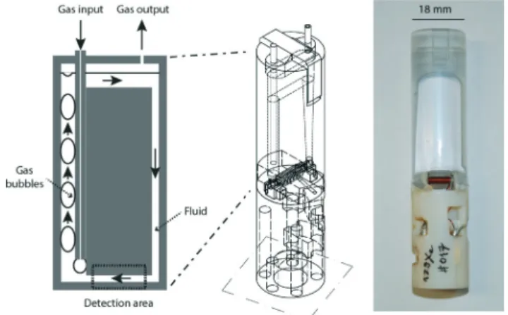
Fluidic system and NMR chamber
Fig. 2 depicts the NMR cell used for this study. The cell was designed in four pieces to be easily assembled after prototyping. The upper part (caps with inlet and outlet chan-nels, fluidic system and micro-coil) contains the fluidic sys-tem: gas exchanger, pump and circulation. The lower part is dedicated to connections between the micro-imaging probe and the rf antenna. It was intended to be easily removed when the solution of interest has to be changed or when cleaning the fluidic part. A 3D printer was used to build the NMR cell, which has the form of an insert that can be plugged into the probe head, like any commercial rf insert. The whole NMR cell fits into the gradient sleeve. In this way, the gradient system of the micro-imaging probe can be used without any modification. NMR detection is performed via a
horizontal solenoid; the electric circuit comprises pre-tuning and matching non-magnetic capacitors and is connected to the probe head. This enables easy tuning of the circuit in the common way using the rods of the probe. The gas output is made via a silicon tube exiting on top of the magnet while the solution flows into its chamber for a total volume of 500 μL and for a detection volume of 5 μL.
To overcome the drawbacks of an external pump, integra-tion of a pumping element inside our NMR cell was investi-gated. Most microfluidic systems need a self-contained active micropump. Micropumps can be classified into two catego-ries: mechanical (electrostatic, piezoelectric, thermo-pneu-matic, electromagnetic actuations, etc.) and non-mechanical (magneto- and hydrodynamic, electroosmotic, electro-wetting, electrochemical and bubble-type) pumping. Bubble-type micropumps appear as good candidates for our system. The pumping effect is based on the periodic expansion and collapse of bubbles generated in the region of higher diame-ter. The bubble outlet direction induces the flow direction of the solution.9Nevertheless in the literature this strategy uses a heating process to create bubbles, which is incompatible with our application. By combining the working principle of a bubble-type pump and the need for dissolution of our hyperpolarized gas, we created a non-heating bubble-type micropump by introducing the gas into the solution via a narrow tube (Fig. 2) positioned at one side of the chamber. This flow of xenon bubbles creates a flow of liquid in our NMR cell (see movie in the ESI†) and gas dissolution due to the large exchange area between the liquid and the gas.
On-flow129Xe NMR experiments
In order to test the performance of the integrated NMR cell (the fluidic and the detection parts),129Xe NMR experiments with laser-polarized gas were performed. Besides its NMR sensitivity, hyperpolarized xenon-129 has the advantage of exhibiting a very large chemical shift bandwidth (more than 300 ppm for monoatomic species) and of being reversibly Fig. 1 Device for driven-flow of gas-loaded solutions into an NMR
magnet. A syringe pump, whose console (1) is connected to the NMR console, pushes in a controlled way via a buffer gas (2) the gas of interest contained in the reservoir (3) to the NMR cell containing the solution (4). This cell is connected to the NMR probe head (5).
Fig. 2 The NMR cell. The principle of the bubble pump (in its top part) is depicted on the left. Middle: 3D drawing of the whole cell; right: picture of one of the cells equipped with a129Xe solenoid coil.
Lab on a Chip Paper
Published on 17 March 2015. Downloaded by CEA Saclay on 22/04/2015 16:02:00.
encapsulated in host systems in which it takes a specific reso-nance frequency.10 The spectral resolution obtained for the dissolved gas and the performance in terms of the rate of gas loading of the solution, a value rarely given in the literature, were the two important parameters that we wanted to esti-mate. Therefore a molecular system in which xenon appears in slow exchange on the NMR time scale with known thermo-dynamics and in–out exchange kinetics was chosen. Aqueous solutions of cryptophane-222-hexacarboxylate were prepared and introduced with a syringe into the NMR cell. With such a molecular system for which the xenon binding constant is known (K = 6800 M−1at 293 K),11the instantaneous concen-tration of xenon in solution can be estimated.
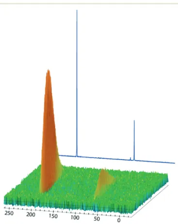
Fig. 3 displays the129Xe NMR spectra recorded on a 0.5 mM solution of cryptophane-222-hexacarboxylate in D2O with the
integrated NMR system. For this experiment, the flow rate was 10 mL per minute. Two consecutive spectra were separated by 1 second, and 90° rf pulses were used. Several observations can be made. When hyperpolarized xenon reaches the detection region, two signals appear: the signal at 195 ppm corresponds to the gas dissolved in water, and the
one at 64 ppm to xenon encapsulated in the cryptophane cavity. Remarkably, there is absolutely no signal at 0 ppm, proving that no xenon bubble is present in the detection region. Also the FWHM of the NMR peaks is less than 50 Hz, confirming the high magnetic field homogeneity. Integration of the xenon signals leads to estimation of the instantaneous total xenon concentration in solution (see Fig. S4 in the ESI†).
Discussion
The system we have developed has many advantages.
First of all, it is very versatile, as it can be installed on a classical micro-imaging probe head with few adaptation steps. This is in particular the reason for the design repre-sented in Fig. 1. We could have imagined introducing the gas from the bottom of the magnet in an LC–NMR-like fashion.12 In this case, the magnetic field outside the magnet would have been higher, and the distance between the gas reservoir and the solution sample would have been lower. But this solution would have lacked flexibility, and would have been reserved to only one probe head. With our system, every change in sample or even rf coil is straightforward. For the same reason, the usual capabilities of a classical probe head can be employed: i) tuning of the electric circuit is performed using tuning rods, and ii) spectrally resolved spectra and spa-tially resolved images can be recorded.
Second, no bubble is present in the detection area, as tes-tified by the absence of signal near 0 ppm in the129Xe NMR spectra. The dissolution yield is high (see below) as well as the xenon polarization level. We have tested various mixtures of nitrogen–xenon in the glass coil without noticeable difference.
Third, both the design of the gaseous reservoir and that of the sample chamber are optimized for short-lived or precious species. The location of the gaseous reservoir can be freely chosen according to the desired magnetic field. The location of the chamber not only minimizes the volume of the solu-tion, but also allows one to conserve it in a high and homo-geneous magnetic field. This can be of importance for appli-cations dealing with hyperpolarized xenon. The design of the chamber enables the use of a horizontal solenoid micro-coil of maximal sensitivity, and avoids the usual convection prob-lems linked to temperature regulation from the bottom of the probe.
The efficiency of the bubble pump is high, and infuse flow rates between 1 and 10 mL min−1give successful results with hyperpolarized xenon. The experiment shown in Fig. 3, performed with a high flow rate value of 10 mL min−1, was intended to show that even in such conditions no bubble was observed, but did not use in an optimized manner the hyperpolarized gas (see Fig. S2 in the ESI†).13 In another – more realistic – example shown in Fig. 4, the flow rate was 1 mL min−1; two consecutive129Xe spectra were separated by 500 ms, and 90° rf pulses were used. Under such conditions, it was possible to observe the dissolved xenon signals for about 8 minutes. As mentioned above and detailed in the Fig. 3 129Xe NMR experiment performed with the driven-flow device.
Two consecutive spectra are separated by 1 second. 500 μL of a 0.5 mM aqueous solution of cryptophane-222-hexacarboxylate fills the reservoir of the NMR cell. Hyperpolarized xenon, prepared in batch mode, is pushed by the syringe containing nitrogen. The peak at 195 ppm corresponds to xenon dissolved in water, and the peak at 64 ppm to xenon in cryptophane. The displayed 1D spectrum corresponds to the projection. Note that the small peak at 73 ppm reveals the pres-ence of residual cryptophane.
ESI,† the instantaneous total concentration of xenon can be estimated (green curve) from the ratio between the signals of dissolved xenon (in red) and the xenon@cryptophane signal (in blue). Remarkably, at this flow rate the xenon concentra-tion is nearly constant, with an average value of 4.0 ± 0.5 mM. Given that the detection volume is known (5 μL according to the recorded magnetic resonance images, see Fig. S1 in the ESI†), and that hyperpolarization is systemati-cally destroyed by each 90° rf pulse, the total number of moles of xenon detected can be estimated and compared to the initial amount of gas in the syringe (which can be esti-mated through simple weighing of the glass coil before the transfer and after evacuation). In the experiment in Fig. 4, the measurement indicates that ca. 15% of the quantity of xenon in the syringe has been detected in the dissolved state, a value that is satisfying for us.
A detailed look at the results in Fig. 4 reveals the oscilla-tory character of the xenon signals (see Fig. S3 in the ESI†), which is always observed at such flow rates (but not for high rates as in the experiment in Fig. 3). This is due to the
discrete nature of bubbling, and is related to the inner diam-eter of the capillary for the gas input. In the next version of the bubble pump, the capillary will end with many small holes in order to reduce the size of the bubbles and to induce a continuous flow rate, even at low speed.
The ratio between the two peaks remains nearly constant all throughout the series. It means that hyperpolarization dis-appears before a significant decrease in the dissolved xenon concentration is detected. Therefore it is possible to extract from the second part of the curves the apparent xenon relaxation time T1(see Fig. S3 in the ESI†). A value of 294 s was found.
Conclusion
We have conceived an integrated solution to optimize the dissolution of a short-lived or precious gas in small quanti-ties of liquids, and to optimize NMR detection of the re-sulting solution. By using 3D printing, the problems related to cleanroom techniques are avoided, and a cheap device that enables easy replacement of not only the solution of interest but also of the rf detection part is proposed. Such a low-cost and disposable system is fully compatible with spectroscopy and imaging, as the spectral and spatial resolutions are not significantly degraded. Our device is composed of a solenoid coil of millimetric size for rf detection as it is the most sensi-tive design and is perfectly adapted to our experiments, but obviously, further miniaturization could be applied via the use of planar or microslot probes,14at the price of a worse rf homogeneity. In this work, xenon is hyperpolarized in batch mode, but of course a further step could also be to miniatur-ize the optical pumping step15and insert it in the NMR mag-net, close to the bubble pump and the NMR chamber.
In the current article, the proof-of-concept has been made via hyperpolarized 129Xe NMR experiments, but we have checked that for other gases such as H2or N2the
bub-ble pump still works. Here a judicious choice of the molecu-lar system enabled us to (roughly) estimate the instantaneous concentration of dissolved xenon during the operation of the bubble pump, and in the future will enable us to optimize the experimental conditions. Also future studies will be directed towards further minimization of the solution vol-ume, as well as optimization of the experimental conditions (pressure in the syringe, flow rate, etc.) and finally simulta-neous NMR detection of129Xe and1H nuclei.
Experimental
Materials and methods
Driven-flow device. A non-magnetic syringe pump (2) (Harvard Apparatus, MRI-compatible model PHD2000) is fixed on top of the NMR magnet in a magnetic field of 100 G. At the beginning of the experiment, the syringe is filled with nitrogen. The gas of interest – hyperpolarized noble gas or para-hydrogen– is produced in batch mode and is contained in a Pyrex reservoir or glass coil (3). This reservoir is also fixed on top of the magnet; it is connected via silicon tubes Fig. 4 a)129Xe NMR experiment performed with a 1.3 mM solution of
cryptophane-222-hexa-carboxylate and a gas flow rate of 1 mL min−1. Two consecutive spectra are separated by 0.5 second. b) Areas of the signals of dissolved xenon (in red) and of xenon in cryptophane (in blue). c) Estimation of the instantaneous concentration of xenon in solution from these signal areas.
Lab on a Chip Paper
Published on 17 March 2015. Downloaded by CEA Saclay on 22/04/2015 16:02:00.
to the syringe and to the solution placed inside the magnet in the NMR cell. Vacuum can be made in these silicon tubes through a remote primary pump placed beyond the 5 gauss fringe field line. The console of the syringe pump (1) is connected via a TTL port at the TCU3 board of the Bruker Avance II NMR console, precisely on the T2-E slot. The pro-gram set on the syringe pump console trigs the NMR sequence, enabling the use of synchronized acquisition dur-ing continuous- or stopped-flow infusion.
NMR cell fabrication via additive prototyping. Initially, designs of the cell were created using the open source 3D computer-aided design program FreeCAD 0.14. The resulting file (STL format) was used by the Stratasys software to create slices of our 3D device. The printing parts were performed with an Objet30 pro 3D printer (Stratasys, Prairie, Minnesota) using PolyJet technology (ink jet technology). The 3D printer jets fine droplets of a liquid photopolymer followed by UV polymerization. Fine layers accumulate on the build tray to create a precise 3D model. The top part of the NMR cell, including the exchange module, was printed in a PMMA-like photopolymerizable resin, which presents high resolution (VeroClear RGD810 resin (Stratasys), deposited layer of 14 μm) using default support material setting. The lower part (for connection to the micro-imaging probe head) was printed in an ABS-like photopolymerizable resin that with-stands higher temperatures to solder connections (RGD525 resin (Stratasys) deposited layer of 28μm) using default sup-port material setting. This supsup-port material was physically removed with high-pressure water after being weakened in 2 wt.% aqueous NaOH solution for 1 hour at room tempera-ture. To obtain the best properties for the different polymers, a post-process treatment was necessary. Polymerization of the PMMA parts was completed under light (a classic desk lamp) at 40 °C for 6 hours. Polymerization of the ABS parts was ended by an annealing procedure that consists of a first stage at 50°C for 2 hours, a second stage at 60 °C for 2 hours and a final stage at 70°C for 1 hour.
The rf antenna consisted of a solenoid obtained by rolling up a 250μm diameter copper wire around a fine glass tube (1.8 mm exterior diameter and 1.0 mm interior diameter). The number of turns depends on the resonance frequency of the observed nucleus and the probe head used. For example, for proton measurement in an 11.7 T narrow bore magnet with a micro-5 Bruker probe head, use of a solenoid of 9 turns was used and addition of a 0.8 pF capacitance in series was necessary to tune it at 500 MHz. Under the same condi-tions, for hyperpolarized129Xe measurement at 138 MHz, 29 turns without any capacitance added were necessary.
Production of hyperpolarized xenon. Xenon enriched with 83% isotope 129 (Euriso-Top, France) is spin-polarized in batch mode via spin-exchange optical pumping, using our home-built setup previously described.16 Then after separa-tion from helium and nitrogen, frozen xenon is stored in a glass coil placed inside a 3 kG solenoid immersed in liquid nitrogen. The glass coil is then transferred to the spectrome-ter, where it cools down to room temperature in a fringe field
value of 100 G delivered by an 11.7 T NMR magnet. It is then connected to the silicon tubing (position (3)).
NMR data processing. All xenon spectra have been apodized by a 10 Hz Lorentzian function before Fourier trans-formation. The curves displayed in Fig. 4 have been obtained using an automation program in Bruker Topspin 3.1.
Acknowledgements
Support from the French Ministry of Research (projects ANR-12-BSV5-0003 MAX4US and ANR-FWF-12-IS04-0006 IMAGINE) is greatly acknowledged. The authors also thank Dr. T. Brotin (ENS Lyon) for providing the cryptophane.
Notes and references
1 B. M. Goodson, J. Magn. Reson., 2002, 155, 157 See for instance.
2 R. A. Green, R. W. Adams, S. B. Duckett, R. E. Mewis, D. C. Williamson and G. G. R. Green, Prog. Nucl. Magn. Reson. Spectrosc., 2012, 67, 1.
3 A. Bifone, Y.-Q. Song, R. Seydoux, R. E. Taylor, B. M. Goodson, T. Pietrass, T. F. Budinger, G. Navon and A. Pines, Proc. Natl. Acad. Sci. U. S. A., 1996, 96, 12932.
4 S.-I. Han, S. Garcia, T. J. Lowery, E. J. Ruiz, J. A. Seeley, L. Chavez, D. S. King, D. E. Wemmer and A. Pines, Anal. Chem., 2005, 77, 4008.
5 S. Bouguet-Bonnet, F. Reineri and D. Canet, J. Chem. Phys., 2009, 130, 234507.
6 C. Boutin, E. Léonce, T. Brotin, A. Jerschow and P. Berthault, J. Phys. Chem. Lett., 2013, 4, 4172.
7 D. Baumer, E. Brunner, P. Blümler, P. Zänker and H. W. Spiess, Angew. Chem., Int. Ed., 2006, 45, 7282.
8 (a) P. Blümler, H. D. Lemke, D. Krieter, H. W. Spiess, F. Wiese and P. P. Zänker, Patent Disclosed 2008, EP000001901782A2; (b) N. Amor, P. P. Zänker, P. Blümler, F. M. Meise, L. M. Schreiber, A. Scholz, J. Schmiedeskamp, H. W. Spiess and K. Münnemann, J. Magn. Reson., 2009, 201, 93; (c) Z. I. Cleveland, H. E. Möller, L. W. Hedlund and B. Driehuys, J. Phys. Chem. B, 2009, 113, 12489; (d) N. Amor, K. Hamilton, M. Küppers, U. Steinseifer, S. Appelt, B. Blümich and T. Schmitz-Rode, ChemPhysChem, 2011, 12, 2941.
9 (a) F. Abhari, H. Jaafar and N. A. M. Yunus, Int. J. Electrochem. Sci., 2012, 7, 9765; (b) A. K. Au, H. L. Lai, B. R. Utela and A. Folch, Micromachines, 2011, 2, 179; (c) F. Amirouche, Z. Zhou and T. Johnson, Microsyst. Technol., 2009, 15, 647.
10 P. Berthault, G. Huber and H. Desvaux, Prog. Nucl. Magn. Reson. Spectrosc., 2009, 55, 35.
11 G. Huber, T. Brotin, L. Dubois, H. Desvaux, J.-P. Dutasta and P. Berthault, J. Am. Chem. Soc., 2006, 128, 6239.
12 V. Exarchou, M. Krucker, T. A. van Beek, J. Vervoort, I. P. Gerothanassis and K. Albert, Magn. Reson. Chem., 2005, 43, 681.
13 Such a flow rate means that ideally 167μL of xenon gas flow through the NMR cell between two acquisitions. This has to be compared to the size of the NMR detection coil (5 μL), and means that at best only 3% of the polarized xenon could be detected.
14 (a) Y. Maguire, I. L. Chuang, S. Zhang and N. Gershenfeld, Proc. Natl. Acad. Sci. U. S. A., 2007, 104, 9198; (b) A. P. M. Kentgens, J. Bart, P. J. M. van Bentum, A. Brinkmann, E. R. H.
van Eck, J. G. E. Gardeniers, J. W. G. Janssen, P. Knijn, S. Vasa and M. H. W. Verkuijlen, J. Chem. Phys., 2008, 128, 052202. 15 R. Jiménez-Martinez, D. J. Kennedy, M. Rosenbluh, E. A.
Donley, S. Knappe, S. J. Seltzer, H. L. Ring, V. S. Bajaj and J. Kitching, Nat. Commun., 2014, 5, 3908.
16 N. Tassali, N. Kotera, C. Boutin, E. Léonce, Y. Boulard, B. Rousseau, E. Dubost, F. Taran, T. Brotin, J.-P. Dutasta and P. Berthault, Anal. Chem., 2014, 86, 1783.
Lab on a Chip Paper
Published on 17 March 2015. Downloaded by CEA Saclay on 22/04/2015 16:02:00.