HAL Id: hal-02991321
https://hal.archives-ouvertes.fr/hal-02991321
Submitted on 10 Nov 2020
HAL is a multi-disciplinary open access
archive for the deposit and dissemination of
sci-entific research documents, whether they are
pub-lished or not. The documents may come from
teaching and research institutions in France or
abroad, or from public or private research centers.
L’archive ouverte pluridisciplinaire HAL, est
destinée au dépôt et à la diffusion de documents
scientifiques de niveau recherche, publiés ou non,
émanant des établissements d’enseignement et de
recherche français ou étrangers, des laboratoires
publics ou privés.
The Solar Orbiter SPICE instrument
M. Anderson, T. Appourchaux, F. Auchère, R. Aznar Cuadrado, J. Barbay, F.
Baudin, S. Beardsley, K. Bocchialini, B. Borgo, D. Bruzzi, et al.
To cite this version:
M. Anderson, T. Appourchaux, F. Auchère, R. Aznar Cuadrado, J. Barbay, et al.. The Solar
Or-biter SPICE instrument. Astronomy and Astrophysics - A&A, EDP Sciences, 2020, 642, pp.A14.
�10.1051/0004-6361/201935574�. �hal-02991321�
September 4, 2019
The Solar Orbiter SPICE instrument
An extreme UV imaging spectrometer
SPICE Consortium: M. Anderson
1, T. Appourchaux
2, F. Auchère
2, R. Aznar Cuadrado
3, J. Barbay
2, F. Baudin
2,
S. Beardsley
1, K. Bocchialini
2, B. Borgo
2, D. Bruzzi
1, E. Buchlin
2, G. Burton
1, V. Büchel
4, M. Caldwell
1,
S. Caminade
2, M. Carlsson
5, W. Curdt
3, J. Davenne
1, J. Davila
6, C. E. DeForest
7, G. Del Zanna
8, D. Drummond
1,
J. Dubau
2, C. Dumesnil
2, G. Dunn
9, P. Eccleston
1, A. Fludra
1, T. Fredvik
5, A. Gabriel
2, A. Giunta
1, A. Gottwald
10,
D. Griffin
1, T. Grundy
1, S. Guest
1, M. Gyo
4, M. Haberreiter
4, V. Hansteen
5, R. Harrison
1, D. M. Hassler
7,
S. V. H. Haugan
5, C. Howe
1, M. Janvier
2, R. Klein
10, S. Koller
4, T. A. Kucera
6, D. Kouliche
2, 17, E. Marsch
13,
A. Marshall
1, G. Marshall
1, S. A. Matthews
11, C. McQuirk
1, S. Meining
3, C. Mercier
2, N. Morris
1, T. Morse
1,
G. Munro
12, S. Parenti
2, C. Pastor-Santos
1, H. Peter
3, D. Pfiffner
4, P. Phelan
9, A. Philippon
2, A. Richards
1, K. Rogers
1,
C. Sawyer
1, P. Schlatter
4, W. Schmutz
4, U. Schühle
3, B. Shaughnessy
1, S. Sidher
1, S. K. Solanki
3, 18, R. Speight
1,
M. Spescha
4, N. Szwec
2, C. Tamiatto
2, L. Teriaca
3, W. Thompson
16, I. Tosh
1, S. Tustain
1, J.-C. Vial
2, B. Walls
9,
N. Waltham
1, R. Wimmer-Schweingruber
13, S. Woodward
1, P. Young
6, 19, A. De Groof
14, A. Pacros
15, D. Williams
14,
D. Müller
15?1 RAL Space, STFC Rutherford Appleton Laboratory, Harwell, Didcot, OX11 0QX, UK 2 Institut d’Astrophysique Spatiale, 91405 Orsay Cedex, France
3 Max-Planck-Institut für Sonnensystemforschung, Justus-von-Liebig-Weg 3, 37077 Göttingen, Germany 4 PMOD/WRC, Dorfstrasse 33, 7260 Davos Dorf, Switzerland
5 Institute of Theoretical Astrophysics, University of Oslo, P.O. Box 1029 Blindern, 0315 Oslo, Norway 6 NASA Goddard Space Flight Center, Greenbelt, MD, USA
7 Southwest Research Institute, 1050 Walnut Street, Boulder, CO, USA
8 DAMTP, Centre for Mathematical Sciences, University of Cambridge Wilberforce Road Cambridge CB3 0WA, UK 9 Southwest Research Institute, 6220 Culebra Rd, San Antonio, TX, USA
10 Physikalisch-Technische Bundesanstalt, Abbestraße 2–12, 10587 Berlin, Germany
11 University College London, Mullard Space Science Laboratory, Holmbury St. Mary, Dorking, Surrey, RH5 6NT, UK 12 ESR Technology Ltd, 202 Cavendish Place, Birchwood Park, Warrington, Cheshire, WA3 6WU, UK
13 Division for Extraterrestrial Physics, Institute for Experimental and Applied Physics (IEAP), Christian Albrechts University at
Kiel, Leibnizstr. 11, 24118 Kiel, Germany
14 European Space Agency, ESAC, Camino Bajo del Castillo s/n, Urb. Villafranca del Castillo, 28692 Villanueva de la Cañada,
Madrid, Spain
15 European Space Agency, ESTEC, P.O. Box 299, 2200 AG Noordwijk, The Netherlands 16 ADNET Systems, Inc., Lanham, MD, USA
17 CESAM SEED, 52B Bd Saint-Jacques, 75014 Paris
18 School of Space Research, Kyung Hee University, Yongin, Gyeonggi-Do, 446-701, Republic of Korea 19 Northumbria University, Newcastle Upon Tyne, NE1 8ST, UK
Received 29 March 2019/ Accepted 19 August 2019
ABSTRACT
Aims.The Spectral Imaging of the Coronal Environment (SPICE) instrument is a high-resolution imaging spectrometer operating at extreme ultraviolet (EUV) wavelengths. In this paper, we present the concept, design, and pre-launch performance of this facility instrument on the ESA/NASA Solar Orbiter mission.
Methods.The goal of this paper is to give prospective users a better understanding of the possible types of observations, the data acquisition, and the sources that contribute to the instrument’s signal.
Results.The paper discusses the science objectives, with a focus on the SPICE-specific aspects, before presenting the instrument’s design, including optical, mechanical, thermal, and electronics aspects. This is followed by a characterisation and calibration of the instrument’s performance. The paper concludes with descriptions of the operations concept and data processing.
Conclusions.The performance measurements of the various instrument parameters meet the requirements derived from the mission’s science objectives. The SPICE instrument is ready to perform measurements that will provide vital contributions to the scientific success of the Solar Orbiter mission.
Key words. Sun: UV radiation – Sun: transition region – Sun: corona – Instrumentation: spectrographs – Techniques: imaging spectroscopy – Methods: observational
SPICE
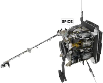
Fig. 1. Solar Orbiter spacecraft, with parts of the side panels removed to show the SPICE instrument.
1. Introduction
The Solar Orbiter mission (Müller et al. 2013, 2019), scheduled to launch in February 2020, will study the Sun and inner helio-sphere with a set of remote-sensing instruments observing the Sun and solar corona and a set of in-situ instruments measur-ing the solar wind around the spacecraft. Together, the ten Solar Orbiter instruments will provide a complete description of the plasma making up the solar wind – its origin, transport and com-position – vastly improving on the Helios mission (Schwenn & Marsch 1990) launched in 1974. Solar Orbiter reaches a min-imum perihelion of 0.28 AU after a series of gravity assists from Venus and Earth, which will also raise the inclination of the orbital plane to above 30◦ from the ecliptic plane (Garcia-Marirrodriga & et al. 2019). The Solar Orbiter minimum perihe-lion of 0.28 AU is very similar to the Helios periheperihe-lion of 0.3 AU, but combined with its unique out-of-ecliptic vantage point, Solar Orbiter will be able to address a fundamental question of solar physics: How does the Sun create and control the heliosphere?
Solar Orbiter will combine in-situ measurements with high-resolution remote-sensing observations of the Sun in a systemic approach to resolve fundamental science problems needed to achieve this objective. These problems include the sources of the solar wind, the causes of eruptive releases of plasma and magnetic field from the Sun known as coronal mass ejections (CMEs), the evolution of CMEs and their interaction with the ambient solar wind flow, and the origins, acceleration mecha-nisms and transport of solar energetic particles that may be haz-ardous to both human explorers and robotic spacecraft that op-erate in the highly variable environment outside of Earth’s mag-netosphere.
While essential to meeting Solar Orbiter’s scientific ob-jectives, the mission’s orbit also poses specific challenges to the remote-sensing instruments. For example, the changing dis-tances to Sun and Earth result in large variations of the thermal conditions and telemetry rates along each orbit, respectively. The strategies devised jointly by the remote-sensing instruments to alleviate these constraints are described in Auchere et al. (2019). The SPICE instrument (Fig. 1) is a high-resolution imag-ing spectrometer operatimag-ing at extreme ultraviolet (EUV) wave-lengths from 70.4 nm−79.0 nm and 97.3 nm−104.9 nm. It is a fa-? Corresponding author: D. Müller, e-mail: [email protected]
cility instrument on the Solar Orbiter mission, funded by ESA member states and ESA. SPICE is allocated 45.3 Gbits of data per six-month orbit, to be acquired nominally during three ten-day remote-sensing windows, which corresponds to an average data rate of 17.5 kbit s−1. Most scientific objectives do not re-quire downloading of full spectra but only selected windows cen-tred on typically ten spectral lines of interest. Further reduction of the data volume can be obtained either by data compression or by computing on board the total intensity of the lines. The allocated resources do not impose compressing the data beyond a ratio of 20:1 (Sect. 7.9). In Sect. 10, we provide examples of observations that illustrate the ability of SPICE to operate within the Solar Orbiter constraints.
SPICE will address the key science goals of Solar Orbiter by providing the quantitative knowledge of the physical state and composition of the plasma in the solar atmosphere, in partic-ular investigating the source regions of outflows and ejection processes that link the solar surface and corona to the helio-sphere. SPICE is of particular importance for establishing the link between remote-sensing and in-situ measurements as it is uniquely capable of remotely characterising the plasma prop-erties of source regions, which can directly be compared with in-situ measurements taken by the Solar Wind Analyser (SWA) instrument suite (Owen & et al. 2019). In magnetically closed regions, SPICE will play an essential role in characterising the turbulent state of the plasma over a wide range of temperatures from the chromosphere into the hottest parts of the corona. This is essential to understand which processes heat the plasma and drive the dynamics we observe, be it through waves, field-line braiding, or reconnection.
2. Scientific objectives and opportunities
The main science goals of SPICE are related to our understand-ing of the complex dynamic connection between the Sun and the inner heliosphere. In this sense, the scientific focus is on studies that combine the remote-sensing and the in-situ instruments on Solar Orbiter to work as one comprehensive suite. At the same time, the unique instrumental capabilities of SPICE will also al-low stand-alone studies that will address other unsolved prob-lems in solar physics.
By observing the intensities of selected spectral lines and their spectral profiles, SPICE will allow the temperature, den-sity, flow, elemental composition and the turbulent state of the plasma in the upper solar atmosphere to be characterised. Emis-sion lines originating between the top of the chromosphere and the low corona cover the temperature range from 10,000 K to 2 MK, augmented by two 10 MK lines seen in flaring plasma (see Table 1).
Following a discussion of the observables provided by SPICE in Sect. 2.1, we present a selection of scientific topics that will be addressed by SPICE (Sect. 2.2). Naturally, this list will be incomplete, but should give a flavour of the scientific op-portunities provided by SPICE.
2.1. Observables provided by SPICE
SPICE is capable of measuring the full spectrum in its two wavelength bands. To optimise the science data return within the given telemetry budget, only the full profiles of the strong emission lines (marked in Table 1) will be measured routinely. This will provide the intensities, Doppler shifts and widths of the lines, from which the non-thermal broadening can be de-termined. The accuracy of the line shifts determined through
Table 1. Selection of spectral lines covered by SPICE.
Ion λ [Å] log T [K] Intensity [ph.pix−1.s−1]
AR QS Ref. ?H i 1025.72 4.0 883.5 372.2 [1] C ii 1036.34 4.3 17.6 21.1 [1] ?C iii 977.03 4.5 563.7 312.1 [1] S v 786.47 5.2 31.6 3.4 [1] O iv 787.72 5.2 56.1 6.0 [1] O v 760.43 5.4 59.5 1.9 [1] ?O vi 1031.93 5.5 8268.2 139.0 [1] ?O vi 1037.64 5.5 2951.3 66.19 [1] Ne vi 1005.79 5.6 15.4 0.3 [1] Si vii 1049.25 5.6 7.5 - [1] ?Ne viii 770.42 5.8 63.9 7.8 [1] Mg viii 772.31 5.9 9.2 - [1] Mg ix 706.02 6.0 3.0 0.9 [1] Fe x 1028.04 6.0 10.1 4.7 [1] Mg xi 997.44 6.2 1.7 0.6 [1] ?Si xii 520.67† 6.3 31.2 2.5 [2] Fe xviii 974.84 6.9 6.9 - [2] ?Fe xx 721.55 7.0 1428.2 - [2]
Notes. For each line the rest wavelength, λ, the approximate logarithmic line formation temperature, T , and the number of photons detected by SPICE for active regions (AR) and quiet Sun (QS), are listed. The last column provides the reference for the solar flux used to simulate SPICE observations. The intensities are for the 200
slit binned over two spatial pixels. Lines marked with a ? are strong lines for which full line profiles can routinely be returned. For the weaker lines, the intensity integrated across the line will be computed on-board and sent down. The Fe xx intensity is from a M7.6 flare. Si xii, marked by†
, will be observed in the second spectral order. This line and Fe xviii intensities are for off-limb observations. [1] Curdt et al. (2001), [2] Curdt et al. (2004).
centroiding will be of the order of 5 km s−1at the longer wave-lengths (depending on the signal-to-noise ratio). There is an op-tion of on-board summing of the line profiles and, separately, of the adjacent background. This will be particularly useful for the weaker lines observed with shorter exposure times, where the limited signal-to-noise ratio may prevent determining line shift and width, but the intensity summed across the line can be ob-tained and downloaded, while using very little of the allocated telemetry. Maps of line intensities, shifts, and widths will be pro-vided as high-level data products.
In addition to these products that are directly deducible from the line profiles, further higher-level data products can be de-rived. First and foremost is the possibility to investigate the el-emental abundances, and in particular the separation of the ele-ments according to the first ionisation potential (FIP). Through the FIP effect, there is a preferential enhancement of elements of low FIP compared to those with high FIP, often called the FIP bias (Fludra & Schmelz 1999; von Steiger et al. 2000). The en-hancement depends on the source region, see a recent review of observations in (Del Zanna & Mason 2018).
The carefully selected lines from low-FIP elements (S, Si, Mg, Fe) and high-FIP elements (H, C, O, Ne) will allow maps of the FIP bias to be produced from SPICE data. The broad tem-perature coverage from 10,000 K to 10 MK (see Table 1) will be well suited to study the thermal structure of the solar atmosphere, all the way from the chromosphere to the corona, occasionally even including hot flare plasma around 10 MK. Spatial maps of the emission measure can be computed in this temperature range.
The spatial resolution of SPICE (along the slit) will be about 400. At perihelion (0.3 AU), this resolution corresponds to 1.200 for an instrument observing from Earth orbit. This is comparable to, or better than most previous EUV spectrographs. The spa-tial resolution of Hinode/EIS (Culhane et al. 2007) is about 200, and SOHO/SUMER (Wilhelm et al. 1995) provided a similar or slightly better resolution. Only the most recent IRIS spectrome-ter (De Pontieu et al. 2014) provides a resolution of about 0.400 that is significantly better than SPICE.
In contrast to EIS and IRIS, SPICE provides a much more comprehensive temperature coverage of the transition region, with lines spaced closely over a wide range of temperatures (see Table 1). EIS is mostly sensitive to hot plasma above 1 MK, while IRIS, designed to observe the Sun’s chromosphere and transition region, is mostly blind to the temperature range from 0.3 MK to 8 MK. While SUMER could observe a temperature range wider than SPICE, it had to step through wavelengths to record spectral profiles, so that it needed considerable time to cover line profiles emitted over the full temperature range. In contrast, SPICE records all the lines simultaneously. This is a major advantage when studying the often very dynamic solar at-mosphere.
In terms of temporal cadence, SPICE is comparable to pre-vious EUV spectrometers. The brightest lines can be observed with exposure times of 1-5 s, while 30-60 s exposures are envis-aged for comprehensive coverage of weaker lines. This allows dynamic phenomena to be followed in a fashion comparable to previous instruments (although with restrictions set by the lim-ited telemetry). Considering its performance, SPICE will pro-vide unique sets of data. SPICE will be able to take full advan-tage of the special vanadvan-tage points close to the Sun and from high latitudes offered by Solar Orbiter during the extended mission, and it will always operate in concert with other remote-sensing and in-situ instruments.
2.2. Science together with other Solar Orbiter instruments Solar Orbiter’s vantage point of out-of-ecliptic latitudes will al-low an unprecedented view of the poles. SPICE will carry out the first-ever out-of-ecliptic spectral observations of the solar po-lar regions. SPICE will provide maps of outflow velocities and identify the sources of the fast solar wind inside the polar coro-nal holes, connecting them to solar wind structures observed by in-situ instruments. Joint observations with the SWA/HIS sensor will allow the testing of models of the fast solar wind (Fludra & Landi 2018).
The magnetic fields near the poles are poorly known, and So-lar Orbiter will provide major advances in this direction through the PHI instrument (Solanki et al. 2019). In this context, SPICE can provide the response of the upper atmosphere to the surface magnetic field in a globally open magnetic environment. The in-vestigation of the emission from plasma over a wide range of temperatures will show if the heating mechanisms in the mag-netically closed quiet Sun at lower latitudes are comparable to those in the globally open coronal hole regions near the poles.
Another important goal of SPICE, together with the other remote-sensing instruments, is to understand small-scale heating events in the corona. Here the line profiles from SPICE will pro-vide the crucial information on the turbulent state of the plasma through the analysis of the non-thermal broadening. Likewise, propagating waves that transport energy through the atmosphere reveal themselves through the spectral profiles. For example, a non-compressible wave like an Alfvén wave, will not be di-rectly visible in imaging observations, but will leave an imprint
in spectral data. The very good coverage in temperature will al-low SPICE to determine the resulting thermal structure of the transition region (through the emission measure) with consid-erably improved resolution compared to previous imaging and spectroscopic observations. In combination with the EUV imag-ing observations by EUI (Rochus & et al. 2019) that will provide diagnostics of the spatial and temporal evolution, these SPICE observations will offer a new and comprehensive picture of the state of the plasma over a range of coronal structures. In partic-ular, SPICE can carry out further studies of the coronal heating, through correlations of the transition region emission with the magnetograms in active regions (Fludra & Warren 2010). Stud-ies of the ubiquitous magnetoacoustic waves, for example, above sunspots (Fludra 2001) or in coronal holes (Banerjee et al. 2011) will also be possible.
Solar Orbiter’s vantage point at high latitudes will also pro-vide a new view at structures near the equator. SPICE and EUI will have a novel view of, for example, loops connecting the plage regions near the preceding and trailing sunspot in an ac-tive region. Such loops run mostly in the east-west direction and can only be viewed edge-on from Earth.
SPICE will play a crucial role in understanding the coupled system of the Sun and the inner heliosphere, the overarching sci-ence goal of Solar Orbiter. Only a spectrometer can provide re-liable tracers connecting measurements by in-situ instruments in the inner heliosphere to the near-surface regions of the Sun, ob-served remotely.
On the one hand, the Doppler maps provided by SPICE will provide information on the source region of the solar wind streams, for example in the vicinity of active regions or within coronal holes. On the other hand, SPICE will provide maps of the FIP bias that might be a helpful tracer to identify the source of the solar wind. In such investigations PHI will provide mea-surements of the underlying (changing) magnetic field and EUI will provide images of the temporal and spatial structures of the chromospheric features through the Ly-α line. Together, this opens new possibilities to study the acceleration and heating in the actual source region of a solar wind stream that will then be captured and characterised in terms of magnetic field, waves, and particle properties by the in-situ instruments: MAG (Horbury & et al. 2019), RPW (Maksimovic et al. 2019), SWA (Owen & et al. 2019).
Eruptive events, such as CMEs, will disrupt the coronal structures and can be eventually detected by the in-situ instru-ment suite. The radiation from the associated flare will also be detected by STIX (Krucker & et al. 2019). In those cases where the source region has been observed by SPICE, the spectrome-ter will provide crucial information on the initial stages of the magnetic disturbance. The shocks and increased turbulence as-sociated with such an event can be studied through line shifts, and widths and intensity enhancements of spectral lines. With SPICE, these can be followed closely as a function of tempera-ture. Such observations are essential to understanding how (and where) shocks form in the corona. Ultimately, this is the key to understanding the generation of solar energetic particles which, again, can be directly measured by the in-situ instruments, in par-ticular EPD (Rodríguez-Pacheco et al. 2019), and which leave their trace through the FIP bias in the data acquired by SPICE. 3. Instrument overview
The SPICE instrument is an imaging spectrograph that records high resolution EUV spectra of the Sun. The SPICE optical de-sign was first presented in Fludra et al. (2013). The instrument
optics consists of a single-mirror telescope (off-axis paraboloid operating at near-normal incidence), feeding an imaging spec-trometer. The spectrometer also uses just one optical element, a Toroidal Variable Line Space (TVLS) grating (Thomas 2003), which images the entrance slit from the telescope focal plane onto a pair of detector arrays. Each detector consists of a pho-tocathode coated micro-channel plate (MCP) image intensifier, coupled to an active pixel sensor (APS). Particular features of the instrument needed due to the proximity to the Sun include: use of a dichroic coating on the telescope mirror to transmit and thus reject the majority of the solar spectrum (this overcomes the large heat load close to the Sun), a particle deflector to protect the optics from the solar wind, and use of data compression due to telemetry limitations. The mechanical design and layout of the SPICE Optics Unit (SOU) are shown in Fig. 2, and the optical path is plotted in Fig. 3.
As shown in Fig. 3, the light enters the instrument through the entrance aperture. Then an image is formed at the slit by the off-axis parabola mirror. The slit defines the portion of the solar image that is allowed to pass onto a concave TVLS grat-ing, which disperses, magnifies, and re-images incident radia-tion onto two detectors. The two wavebands cover the same one-dimensional spatial field, and are recorded simultaneously. De-tails of the optical path are further described in Sect. 4. The in-strument contains four mechanisms:
– The SPICE Door Mechanism (SDM), which can be actuated to provide a contamination tight seal of the entrance aperture during non-operational periods (both during ground handling and non-operational periods in flight).
– The telescope mirror is mounted onto a two-axis mechanism (tilt and focus), the Scan-Focus Mechanism, that is used to direct different portions of the solar image onto the selected entrance slit and to focus the telescope relative to the en-trance slit. The image of the Sun is repeatedly scanned across the entrance slit. During each scan the image of the Sun is stepped across the entrance slit in increments equal to the se-lected slit width, such that the region of interest is completely sampled.
– A Slit Change Mechanism (SCM) provides four interchange-able slits of different widths, one of which can be selected depending upon the science activities to be conducted. These slits have a 200, 400, 600, and 3000width on the external field of view. They are interchangeable via a slit change mechanism and are arranged on the mechanism in this order.
– A vacuum door mechanism on the Detector Assembly (DA). The MCP and image intensifier used to translate the inci-dent EUV photons into visible light photons that can be de-tected by the detectors must be maintained either at vacuum or in zero humidity during ground handling. Therefore the detector assembly contains a door mechanism which is only opened during vacuum testing on ground, and opened finally once on-orbit.
The instrument structure consists of a stable optics bench with Aluminium honeycomb core and Titanium inserts. Base-plate facesheets, side walls and lids are made of Carbon Fibre Reinforced Plastic (CFRP). This is isostatically mounted to the spacecraft panel by means of Titanium flexures. The structure is designed to have approximately zero coefficient of thermal expansion (CTE), therefore maintaining instrument alignment throughout the wide operating temperature range.
The instrument control function will be provided by a ded-icated electronics box, the SPICE Electronics Box (SEB). The SEB drives and monitors all mechanisms, the acquisition and
processing of all housekeeping telemetry and the processing and packetisation of science data. It controls and communicates with the detector front-end electronics (FEE) via a SpaceWire link. The SEB also contains the SPICE flight software (FSW), which is responsible for all control and monitoring of the instrument, plus the processing and compression of the science data to allow the data rate and volume requirements to be achieved.
4. Optical design
SPICE is a grating-spectrometer (Figs. 2, 3) where a portion of the solar disc is imaged by the single-mirror telescope onto the spectrometer entrance slit. The physical length of the slit is ~2 mm, and for the mirror focal length (see Table 2) it gives an angular size of 110(size of the along-slit instantaneous field of view on the Sun, oriented solar north-south). The slit is imaged by the diffraction grating on the two array detectors. The grating has a concave toroidal surface form, which images the slit with magnification as given in the table; the physical size of the slit image at the detectors is ∼11 mm. This spectrometer magnifica-tion also scales the telescope focal length to give a system e ffec-tive focal length of ~3.3 m. This is needed to give the required imaging-spectrometer spatial and spectral sampling (~100/pixel and ~0.01 nm/pixel), with the given physical pixel-spacing of the array detectors (see Table 2).
The two detector arrays are separated in the focal plane in the dispersion direction according to the two chosen bands, short wavelengths (SW, 70.4 nm–79.0 nm) and long wavelengths (LW, 97.3 nm–104.9 nm). They are each based on a format of 1024×1024 pixels. The slits include square alignment apertures at each end (so-called dumbbells, shown in Figs. 4 and 5), such that the total slit image length is ~140. The detectors are oversized with respect to this image size such that they pro-vide images with spatial sampling along-slit of approximately 140/800 pixels, or ~100/pixel. In the spectral direction the sam-pling is ~9 nm/1024 pixels, or ~0.009 nm/pixel (cf. Table 2). The dispersion relation of the spectrometer is given by the grating equation:
sin(θm)= m · λ
d + sin(θi) , (1)
where d is the ruling spacing, m is diffraction order, θi is the angle of incidence and θmthe angle of diffraction, with values as given in Table 2.
In order to create the 2D images, the 1D instantaneous-FOV (slit FOV) is scanned laterally, over a range of 160, by rota-tion of the telescope mirror. The mirror is mounted on a flex-ure rotation mechanism, driven by a continuous range mecha-nism (piezo actuator), but with a functional minimum step size of 200, due to the mechanism encoder and control system used. The full range of the spectral imaging is thus an area of sun of 140×160 times 2×9 nm wavelength, sampled at ~800×480 points spatially, times 2048 spectral points (maximum size of x-y-λ data cube). The scan is controlled by closed loop, with a minimum time per step of 0.25 s for a step size of less than 1 arcminute. This gives a best maximum frame rate of 3 Hz. For fixed-scan observations, the overheads are reduced to 0.1s per frame, lead-ing to a maximum frame rate of 5 Hz (for the minimum exposure time of 0.1s).
4.1. Imaging resolution
The narrowest slit is 200wide. Because the spectrometer magni-fication is the same in spatial and spectral directions, this
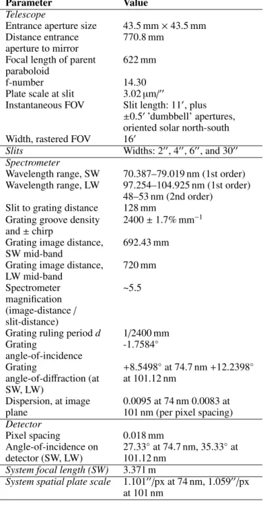
corre-Table 2. Optical system parameters of the SPICE instrument.
Parameter Value
Telescope
Entrance aperture size 43.5 mm × 43.5 mm
Distance entrance aperture to mirror
770.8 mm Focal length of parent
paraboloid
622 mm
f-number 14.30
Plate scale at slit 3.02µm/00
Instantaneous FOV Slit length: 110, plus
±0.50’dumbbell’ apertures, oriented solar north-south
Width, rastered FOV 160
Slits Widths: 200, 400, 600, and 3000
Spectrometer
Wavelength range, SW 70.387–79.019 nm (1st order)
Wavelength range, LW 97.254–104.925 nm (1st order)
48–53 nm (2nd order)
Slit to grating distance 128 mm
Grating groove density and ± chirp
2400 ± 1.7% mm−1 Grating image distance,
SW mid-band
692.43 mm Grating image distance,
LW mid-band 720 mm Spectrometer magnification (image-distance/ slit-distance) ~5.5
Grating ruling period d 1/2400 mm
Grating
angle-of-incidence
-1.7584◦ Grating
angle-of-diffraction (at SW, LW) +8.5498◦at 74.7 nm+12.2398◦ at 101.12 nm Dispersion, at image plane 0.0095 at 74 nm 0.0083 at 101 nm (per pixel spacing) Detector Pixel spacing 0.018 mm Angle-of-incidence on detector (SW, LW) 27.33◦at 74.7 nm, 35.33◦at 101.12 nm
System focal length (SW) 3.371 m
System spatial plate scale 1.10100/px at 74 nm, 1.05900/px at 101 nm
sponds to 0.02 nm spectral width geometrically. However, when the optical-system and detector resolution effects are added, the net spectral resolution is 0.04 nm (full-width half-maximum (FWHM) of line-spread function (LSF): ~4 pixels). The contrib-utors to imaging resolution are listed in Table 3, and each of the contributions is explained in the relevant subsections below.
4.2. The telescope mirror
SPICE has a single-mirror telescope. The mirror is an off-axis paraboloid made of UV-grade fused silica substrate with a clear aperture of 95 mm × 95 mm and focal length of 622 mm. The central area of 50 mm × 50 mm on the substrate has a thin reflec-tive coating of boron carbide (B4C). This single-layer coating is a novel design, which is a result of a compromise providing 30%
Fig. 2. Optics Unit of the SPICE instrument. In this top view into the SPICE Optics Unit, its key components are identified, along with the providing institutes and companies.
Fig. 3. SPICE optical layout. The system parameters are listed in Ta-ble 2.
Table 3. Imaging resolution contributions.
Contribution in pixels (spatial and spectral
directions) Design, including nominal
aberration, 200slit-width × 2-pixel binning
2
Optical Component tolerances contributions
2.5 Position tolerances (build plus
in-flight)
1.5
Detector PSF (FWHM) 2
Residual spacecraft jitter (10 secs)
1
Total (RSS) 4.2
Fig. 4. Field-of-view diagram for SPICE, showing detector size, slit sizes, and spectral ranges (SW: short wavelengths, LW: long wave-lengths, FOC: fibre optic coupler).
EUV reflectance while transmitting the rest of the solar spectrum (UV/VIS/IR) to space via a 45◦fold mirror and an exit aperture. Such a dichroic design greatly reduces the heat load inside the instrument. The thickness of 10 nm of the boron carbide coating was found to be advantageous for this purpose (Schühle et al. 2007).
The mirror substrate and the exit aperture are oversized with respect to the reflective aperture surface. The size is required to pass the angular range of the whole solar disc, for Solar Or-biter pointing at any part of it. The rear side of the substrate has an anti-reflective coating to maximise transmission of the solar spectrum passing through and beyond the reflective front coat-ing.
For imaging in the EUV, the mirror surface quality must be high. Thus, the figure error was specified as ~λ/20 RMS. Mea-sured at 633 nm the RMS figure deviation of the flight mirror was 0.028 waves. Also, the surface roughness must be low to limit scattered light from the whole solar disc while only a very small part of it is passing on to the spectrograph. The
micro-roughness was specified as < 0.2 nm RMS, and the micro-roughness measured by atomic force microscopy was 0.17 nm.
At perihelion, the solar flux at the mirror is ~13 times the so-lar constant, and despite the low absorptance of the mirror over most of the solar spectrum, this results in approximately 3 W of absorbed power, leading to a centre-to-edge thermal gradient of ~20◦C in the mirror, as the silica has low thermal conduc-tivity. However it also has low thermal expansion, so the result-ing ‘swellresult-ing’ of the mirror’s front surface is small (predicted ~0.04µm), which is not significant for aberrations, and is in-cluded in the term ’optical component tolerances’ in table 3. This was also verified by tests, using a mirror illuminated with a solar-simulator UV beam, while monitoring its surface form using an optical test interferometer.
The mirror is mounted on a scan-focus mechanism (SFM, see Sect. 6.2), which performs the angle scan (see above) using a piezo drive, as well as a motor-driven focus adjustment (range of ±0.5 mm). This focus adjustment is to allow for possible changes in the optics assembly dimensions from on-ground to in-flight, in particular for the varying thermal environment during the mis-sion.
Due to the proximity to the Sun the telescope mirror surface and the boron carbide coating are vulnerable to the high fluence of solar wind particles expected during the mission. As a pro-tective measure, a solar wind particle deflector is included in the entrance baffle of the instrument structure. It consists of conduc-tive plates with an applied voltage of −2.5 kV, which will create an electric field strong enough to deflect incoming low-energy solar particles such as to prevent them from reaching the mirror.
4.3. Spectrometer Slits
The four slits are arranged in-line on a single frame, and to change slits this is raised and lowered within the telescope focal plane, on the linear slit change mechanism. Each slit is an aper-ture etched into a silicon slice of 0.5 mm thickness (vee-groove etch, as shown in Fig. 5), and gold-coated. The three narrow slits are 110long (i.e. having 2 mm physical length), but also with a small square aperture near each end (i.e. at a distance of ±70from centre). These serve to image small regions of the sun (0.50× 0.50) to obtain pointing information during the observations (see Fig. 4). An electron-microscope test image showing the end of one slit and its square aperture is shown in Fig. 5. The 3000 slit (also known as a ’slot’) is 140long, and has no additional square apertures. This element allows pseudo-spatial images to be ac-quired from isolated spectral lines, which can be used for certain science studies (e.g. movies), or for collecting instrument cali-bration data (e.g. detector flat-fielding).
4.4. Diffraction grating
The diffraction grating is of TVLS type, as developed for this type of solar spectrographs. This enables slit-to-array detector imaging to be performed directly with the grating, in order to be able to dispense with additional mirrors normally required for aberration-control (chromatic astigmatism), and thereby greatly increasing the EUV throughput (for near-normal incidence the reflectivity of coatings at these wavelengths is only ~30%). The aberration control over the range of the two detectors requires both toroidal form and varying line-spacing (‘chirp’), that need to be precisely matched. The toroid radii of curvature have to match to ~1%. The grating is holographic, 2400 lines/mm (at grating centre), and with linear ‘chirp’ variation of ~1% of this
Fig. 5. Electron-microscope image of the rear of a SPICE slit (etched silicon). The end of a slit and one of its square dumbbells are shown.
across the used aperture. This level of linear variation is itself controlled to ~5% to match the toroid radii. The surface optical quality has to be similar to that of the telescope mirror, and the used aperture is much smaller (by the factor ~622 mm/128 mm). The reflective coating of the grating is of the same material as that of the mirror, boron carbide, but the thickness was increased to 20 nm to increase reflectivity. This is possible due to the neg-ligible solar heat load on the grating.
The diffraction efficiency of the grating is a critical parame-ter, and was measured (using synchrotron radiation) to be ~9% (absolute efficiency). For the spectrometer build tolerances, the large magnification is a challenge for the grating focus-setting and the correct alignment of the spectrum on the detector. For a de-focus blur radius equal to 1 pixel, the axial distance of the grating from the slit has to be set to within ±50µm. This is a practical challenge in the planning. Since the grating only works optically in the vacuum ultraviolet (VUV), the set up in air has to be done to this accuracy by dead-reckoning, meaning by me-chanical metrology using reference surfaces on the grating sub-strate and the slit mount. The alignment method was to then use a VUV test immediately after this set-up (i.e. before complet-ing the build), to confirm this critical focus and alignment of the grating.
4.5. Detectors
The detector assembly is described in detail in Sect. 6.5. The incident UV light is converted to visible light inside the assem-bly, for detection by two independent sensor arrays, each sized at 1024 pixels square. The active area is large enough to record images of the full length of the slits plus dumbbells, with some margin. However, the detector area limits the wavelength range in each band (see Sect. 9). The pixel pitch of 18µm also sets the spectral and spatial sampling, which in both cases is over-sampled relative to the instrument resolution (see Tables 2, 3).
4.6. Stray-light design
There are two main effects, both due to non-ideal light-scattering in the optical system: out-of-field light and out-of-band light. The out-of-field effect is the light from the surrounding scene, meaning outside of the FOV, that is scattered into the FOV. It
Fig. 6. SPICE Optics Unit: Details of interfaces to spacecraft including flux-exit aperture (upper right).
has a worst-case for the viewing of the relatively faint corona (when spacecraft points at the limb, SPICE will view at up to ~80above the limb). The relatively bright light of the solar disc scatters at instrument baffles and at the optical surfaces. This ef-fect is mainly restricted to the telescope because most of the solar disc is blocked at the slit. The scatter from baffles (vane edges) is kept low by designing the vanes as oversized from the used FOV (i.e. the beam envelope defined by combination of the entrance aperture and the slit) and giving them sharp edges. Also the baf-fle material is CFRP which is absorbing to VUV, and the vanes are designed to block any grazing-incidence light paths from the structure surrounding the optics. The mirror roughness and particulate contamination are kept as low as possible (<0.2 nm RMS, and <100 ppm surface area, respectively).
The out-of-band light is the diffuse scatter within the spec-trometer that adds a constant background level to the measured spectra, adding to the photon noise. This effect is kept low, again by use of baffle vanes, particularly around the slit mecha-nism where there are surfaces close to the beam, by the rough-ness quality of the grating surface and its lines ruling (grating grooves) plus its cleanliness, and by the visible-light blocking of the detector photo-cathode (so called solar-blindness). The grat-ing’s final roughness after the etching of its grooves (~40 nm depth) is 0.8 nm RMS. In the final instrument testing, when imaging spectral lines, the out-of-band level was found to be ~0.1% relative to line peak, at ~0.1 nm from line centre.
5. Mechanical and thermal design 5.1. Mechanical design
The SPICE Optics Unit (SOU) is primarily made of a CFRP-and-aluminium honeycomb optical bench structure, onto which most of the subsystems are mounted, along with CFRP panels to produce a light-tight enclosure and stray-light baffles. The rear of the SOU houses the heat rejection mirror and baffle that allows the unwanted infrared (IR) radiation from the entrance aperture to pass out the rear of the instrument and out to space. These key interfaces can be seen in Fig. 6. The SOU has a total mass of approximately 13 kg and maximum dimensions of 1100 × 350 × 280 mm.
The SOU interfaces to the spacecraft panel with three ‘quasi-kinematic’ mounts; one fixed foot at the front of the unit and two mounted on blades at the rear that allow for the di
fferen-Fig. 7. SPICE Optics Unit: Interface Mounts (left: fixed mount, right: bladed flexible mount).
tial CTE between the optics bench and the spacecraft panel – these are shown in Fig. 7. The mounts (manufactured from ti-tanium alloy Ti-6Al-4V) are optimised in order to be compliant enough to compensate for the ~1 mm in-plane difference in CTE between the spacecraft and optics bench (without distorting the bench), while also being stiff enough for the SOU to meet the minimum resonance frequency requirement of 140 Hz and sur-vive the launch loads (the actual resonance frequency is 224 Hz). The blade mounts were manufactured in the RAL Space Preci-sion Development Facility and heat treated and surface treated in order to maximise their performance.
The optical bench prior to installation of the subsystems can be seen in the upper panel of Fig. 8 and the single-skin honey-comb panels used as stray-light control and stiffening ribs can be seen in the lower panel. The design is based on the use of a very low-CTE CFRP in order to maximise the thermo-mechanical sta-bility of the instrument across a wide range of temperatures. Ini-tial coupon testing using interferometry demonstrated CTE of 0.2–0.7 ppm/°C for a representative sample, although the final optical bench measurement showed a higher (2.5 ± 0.5 ppm/°C) figure which could be accepted by the use of margin within the alignment budget. This increase is thought to be due to stronger interaction between the CFRP face sheet, the adhesive film and the honeycomb core than had been assumed in the theoretical model.
5.2. Thermal Design
The main requirements of the thermal design of SPICE are: – To manage the solar load and maintain all instrument
com-ponents to within their operational and non-operational tem-perature limits
– To control the detectors to a stable temperature of less than −20 °C during all operational periods
– To minimise the heat flow that is rejected (either radiatively or conductively) to the spacecraft thermal interfaces – To ensure that the primary mirror is warmer than its
sur-roundings during the cold early phases of the mission, to avoid contamination of its surface
The primary thermal challenge for the SOU is managing the extreme heat input (~17 kW/m2) during operation at perihelion. The thermal control system must also be compliant during peri-ods with little solar loading, with the conditions during the Earth and Venus gravity assist manoeuvres required for orbit adjust-ment (with additional planetary IR and albedo thermal loads) and
Fig. 8. SPICE optical bench structure without (top) and with (bottom) internal stray-light baffling.
with conditions with the instrument off-pointed from its central axis.
The SOU is accommodated within the spacecraft, behind its heat shield. A feedthrough in the heat shield provides a view for the instrument. The heat shield includes a door that can be used to prevent direct sunlight entering the instrument feedthrough during non-operational periods.
The SOU is, with the exception of two designated radiative and conductive heat rejection interfaces, thermally decoupled from the spacecraft. Conductive decoupling is achieved through the use of low thermal conductivity titanium for the kinematic mounts, and the natural isolation required by the quasi-kinematic mount design. Radiative decoupling is achieved through the ap-plication of a low-emissivity aluminised coating to the external surfaces of the SOU structure.
The thermal design utilises a synthetic quartz (Suprasil® 300) primary mirror with a 10 nm thick B4C coating that re-flects the EUV radiation of interest for science but transmits the visible and near-infrared solar radiation with little absorp-tion. Consequently, much of the high-flux solar radiation enter-ing through the aperture passes through the instrument and is then reflected to space by the herejection mirror (HRM) at-tached to the rear of the instrument. The HRM assembly is a CFRP structure mounted to the rear of the instrument that houses a highly reflective diamond turned aluminium fold mirror.
The majority of the solar radiation that is reflected within the SOU by the primary mirror is intercepted by three pre-slit heat rejection mirrors (mounted before the slit) and reflected to a single high-absorptivity heat dump radiator. As these heat loads
Fig. 9. Predicted thermal energy balance for the SPICE Optics Unit during perihelion operation, at end-of-life.
are relatively low, this re-radiates to the internal surfaces of the spacecraft. The pslit mirrors are configured so that just the re-quired science beam is passed through to the slit (anything that reflects on to them via the primary mirror is not part of the sci-ence beam). Baffles also intercept radiation that either diverges as it comes into the instrument or is off-axis due to the spacecraft pointing away from the Sun centre.
At perihelion, the instrument can survive thermally when the spacecraft is off-pointed by up to 3.5◦in any axis in steady-state, and by 6.5◦ for a period of up to 50 seconds. This gives su ffi-cient margin for nominal spacecraft operations which will never point beyond the solar limb, maximising at 0.94◦ at perihelion. At the distance of 0.7 AU, the steady-state off-pointing limit in-creases to 4.5◦, and at 0.95 AU the spacecraft can be oriented at any attitude without thermally affecting SPICE. The above ther-mal analysis shows how far of an off-axis pointing SPICE can survive (without necessarily being required or able to do sci-ence).
The primary thermal design driver is to manage, at perihe-lion, the solar load incident through the 52×52 mm aperture in the spacecraft heat shield. Fig. 6 illustrates the thermal model predictions for the nominal perihelion case, with end-of-life (EOL) thermo-optical properties. About 66% of the 31.7 W en-tering the SOU cavity is transmitted through the primary mir-ror and reflected directly to space by the HRM. The remaining 10.7 W is absorbed within the SOU structure. Of this, 2.5 W is directed to the heat dump radiator, where it is radiated to the spacecraft. In the perihelion case, the surrounding spacecraft temperature is specified as 50°C. The instrument structure aver-ages about 55°C due to the addition of absorbed solar loads and internal dissipation. It is noted that the view of the HRM struc-ture to deep space provides radiative cooling, which reduces the heating effect of the absorbed solar loads. About half of the inter-nal absorption of solar flux occurs at the primary mirror (at the coating and within the silica substrate). The primary mirror is therefore warmer than its surroundings, operating at about 70°C. The detector assembly is conductively and radiatively iso-lated from the instrument surroundings at the mounting interface using polyether ether ketone (PEEK) standoffs. Heat generated internally and the low levels of parasitic heat to the assembly are rejected to the spacecraft-provided cold element interface. This allows the active pixel sensors within the DA to be passively cooled. They are then individually PID (Proportional-Integral-Differential) controlled by SEB-powered heaters to a set-point of −20°C.
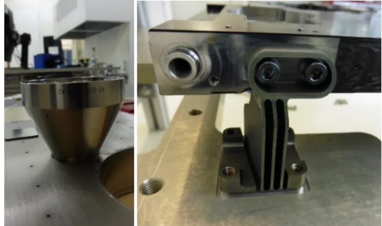
6. Mechanisms and detector assembly design 6.1. SPICE Door Mechanism
The SPICE Door Mechanism (SDM) provides a contamination seal at the entrance aperture of the instrument. It protects the highly sensitive internal optics during non-operational periods during the ground integration and test phase, and during the cruise and non-operational phases in flight. The mechanism con-sists of the door itself (with a highly reflective finish and spher-ical shape to reject the incoming high intensity solar flux dur-ing some flight phases), which is articulated on linear beardur-ings and driven by a stepper motor (with reduction gear-box) and ball screw. The door maximum temperature is ~125◦C when closed at perihelion. However, the door and mechanism design is not thermally qualified for the transient case of being opened or closed while sun-illuminated, and this means that for these oper-ations, the outer heat-shield door must be closed.
The SDM provides the defining aperture for the instrument optical design, including a knife edge to control the stray-light impact of the aperture and reject the oversized beam passing through the heat shield feedthroughs. The door forms a labyrinth seal which is contamination-tight, but allows purging of the op-tical cavity during Assembly, Integration and Verification (AIV) up to launch. The SDM is designed and qualified for up to 100 open-and-close cycles so that it can be used repeatedly both dur-ing AIV and durdur-ing flight between the remote-sensdur-ing windows (to limit contamination from the spacecraft entering the instru-ment). The door opening and closing operations involve driving through motor steps, between the end positions. These are de-tected by position switches at each end of the range; in addition, the steps are counted. At the step rate used, the time required to open and close is approximately 50 s. The component parts of the SDM design are illustrated in the left panel of Fig. 10 and the flight model mechanism (integrated to the front panel of the SOU) is shown in the right panel.
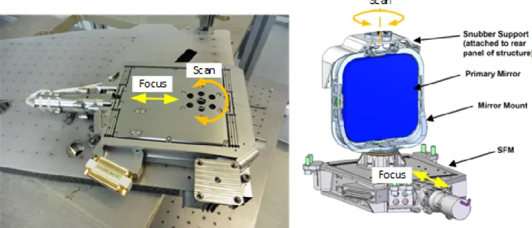
6.2. Scan-Focus Mechanism
The required range of motion for the mirror is 0 − 80in rotation (about an axis parallel to the slit-direction), and ±0.5 mm in lin-ear motion (in the focus direction). At the same time, the mech-anism must have high stiffness in the other degrees of freedom to maintain alignment and stability. This is achieved by using a flexure-based design, with multiple blade flexures for strength. It is a two-stage design comprising (1) a linear stage for focus, driven by a roller-screw mechanism with stepper motor, and (2) a rotation (scan) stage. This is mounted on the linear stage, and is driven by a piezo-electric actuator via a lever arm. The mirror assembly itself is mounted on this rotation stage, and the adjust-ments for optical alignment during the build are made at this interface.
The motions of both stages are sensed by linear variable dif-ferential transducer (LVDT) sensors. The sensor for rotation is connected to a lever arm, which amplifies its displacement to al-low a suitable accuracy of the sensor for the control system. This rotation (scan) has closed-loop control to give the required sta-bility and step resolution (≈ 200). This mirror scanning is used regularly during many of SPICE’s observing sequences, and the response time for scan stepping with a small range is typically 0.25 secs. The linear (focus) stage has step size 0.4 mm, and po-sition accuracy is < 2µm at a given temperature. During obser-vations the focus setting is changed only infrequently, for
exam-ple during calibrations or after change in instrument temperature (depending on mission phases).
6.3. Slit Change Mechanism
The slit change mechanism has the function of positioning any one of the four slits into the active slit position, to the re-quired absolute and stability tolerances (in particular as regards the spectrometer focus and spectral calibration). The slits are mounted in-line in a single carrier mounted to the mechanism stage. The physical length of each slit is approximately 2.5 mm (slit length including dumbbells, for 140angular size on the Sun), and the spacings between adjacent slits are 5, 6, and 5 mm, so the total range of motion needed is 16 mm plus margin. To change from one slit to any other, is a single linear movement. Due to the fixed mechanism speed the time taken is a minimum for move between adjacent slits, to a maximum for a move between the end slits
For the mechanism design the slits carrier is mounted be-tween two large leaf-spring flexure blades (titanium), in order to provide the required motion range (along-slit direction) while maintaining stiffness in the across-slit (spectral) and focus axes. It is driven by a stepper motor, which drives a Rollvis satellite screw, which translates the rotary output of the stepper motor into linear motion. The step size of the slit motion is 0.02 mm. The assembly includes mu-metal magnetic shielding that greatly reduces the magnetic signature of the Sagem stepper motor. A limit switch is implemented at one end of the range of travel, 0.25 mm from the 600 slit. All operations of the mechanism are performed by counting the number of motor steps moved rela-tive to this limit switch, which defines the ‘zero’ position. Stan-dard operations will include driving the mechanism back to the limit switch on a regular basis (after every few slit changes), to ensure that the positional reference is maintained. The standard travel speed of 0.5 mm/s allows an adjacent slit to be selected in 10 − 12 s. A slower drive speed is used for finding the limit switch, but the reset operation can always be completed in less than 1 minute, from any given starting position.
6.4. Detector Assembly Door Mechanism
The primary purpose of the detector assembly door mechanism is to control contamination, mainly molecular, as well as humid-ity, which can both be detrimental to the accuracy of the detector as well as the functionality of the MCP. It is critical that the door never be opened when not at vacuum or in<30% humidity envi-ronment, or the intensifiers will be damaged.
The actuator for the door mechanism is a controllable drive actuator. This motor was selected as a smaller mass option to the other motors on the SPICE project while still meeting require-ments. The motor is able to achieve 2.3 Nm of torque across the operating temperature range of the SPICE DA. Conversion of the rotary stepper motor motion into linear displacement will be performed using a worm gear, while a pin-and-slot feature on the door part will allow the door to open and close.
Due to the contamination requirements of the instrument and the relatively undemanding life requirements, dry lubrication is used on the motor mechanism. The door actuation cycles will be low for this mechanism. The qualified number of cycles for this mechanism is one in flight and 20 during ground testing.
Fig. 10. Door Mechanism. The drawing on the left highlights its components, the picture on the right shows the assembled flight model.
Fig. 11. Scan-Focus Mechanism. The picture on the left highlights focus and scan directions, the drawing on the right shows how the instrument’s primary mirror is mounted on the mechanism.
6.5. Detector Assembly design
The SPICE DA (Fig. 13) consist of two independent, identical, intensified APS camera systems mounted in a common sealed housing. Each camera consists of a HAS2 (High Accuracy Star-tracker 2) 1024×1024 pixels format complementary metal-oxide semiconductor (CMOS) APS with digital readout electronics fed by a KBr-coated micro-channel plate intensifier. This DA is radiation-hard, and has significant heritage through multiple orbital and sub-orbital missions.
The main elements of the DA are shown in Fig. 14. The SPICE intensifier tubes consist of a micro-channel plate and a phosphor screen packaged in a lightweight housing. Each pro-vides a nominally 25 mm diameter active area that circumscribes the sensor active area. A KBr photocathode is deposited on the front surface of the MCP to enhance response in the SPICE pass-bands, while remaining visible-light blind. Photons absorbed by the KBr layer are converted to photoelectrons and amplified
through the MCP based on the applied voltage across the MCP. The nominal MCP voltage from the high-voltage power supply (HVPS) is 850 V (up to 1200 V possible), unless adjustments are necessary due to detector ageing.
Electrons exit the 6µm MCP pores and are accelerated by a 2800 V potential across a sealed proximity gap (0.5 mm) onto an aluminised phosphor screen deposited onto a fibre-optic output window. Electrons are converted into a visible-light image at the phosphor screen. The resulting image is transferred through a fi-bre optic coupler to the APS sensor. A direct bond between the fibre optic and the APS seals the APS active area and eliminates environmental contamination on the APS. The fibre optic cou-pler is similarly bonded to the MCP fibre-optic output window, again eliminating environmental contamination. The MCPs are scrubbed to stabilise the MCP gain against localised charge de-pletion. After scrubbing, the MCP housing is maintained at low humidity levels until launch to maintain sensitivity.
Fig. 12. Slit Change Mechanism.
The APS detectors are cooled (by conductive link to the spacecraft cold-element) to minimise the dark-current, and the temperature is stabilised using heaters on the detector thermal straps to achieve −20◦C. This approach allows the spacecraft cold element temperature to vary during the orbit, while still achieving stable detector performance (which is sensitive to tem-perature).
The front-end electronics (Sect. 7) are located close to the focal plane to maintain the integrity of the clocking and ana-logue output signals. Within the front-end electronics, a Field-Programmable Gate Array (FPGA) will accept configuration commands and generate the timing signals needed to operate the HAS2 sensor as configured. The analogue video signal from the sensor will be digitised to 14 bits precision.
7. Electronics (including FPA hardware and flight software)
The SPICE instrument has two electronic units: the SPICE Elec-tronics Box (SEB), which contains the control and data process-ing, and the Front-End Electronics (FEE), which form part of the detector assembly within the SOU.
7.1. SPICE Electronics Box The SEB circuit boards are:
(a) High Voltage Power Supply (HVPS) for the MCP, Gap and Particle Deflector
(b) Data Processing Module (DPM) incorporating the spacecraft interface, signal processing and instrument control
(c) Two Mechanism Interface Modules (MIM) driving the mo-tors, scan mirror, position sensors and SOU heaters
(d) Low Voltage Power Supply (LVPS) which converts the spacecraft 28V to the SEB internal supplies
(e) Backplane which is used to transfer the various signals be-tween the other 4 circuit boards.
7.2. Mechanical Design
The SEB utilises a single chassis with 4 mm wall thickness that houses the six circuit assemblies. The five plug-in cards are de-signed with wedge type card retainers that interface to machined
card slots, providing both structural support and a conductive thermal path to the chassis. After all modules have been inserted into the chassis, a single front panel is installed on the front, which along with rabbet joints at all panel to panel mating, min-imises electromagnetic radiation exiting the chassis, and cos-mic radiation entering the chassis. The chassis uses vent holes sized such that there is adequate ascent depressurisation capa-bility while maintaining a small aspect ratio to give good EMC (electromagnetic compatibility) performance.
7.3. Data Processing Module
The DPM provides essential data processing, instrument com-manding and science operations management for the SPICE in-strument. The DPM is the central part of the SEB and performs the following functions:
– Hosts 8051 microcontroller and flight software (FSW) – Command & telemetry interface to the spacecraft – Control of instrument mechanisms
– Command & control of FEE – Image processing and compression
– Control of the high and low voltage power supplies
Control and management of the mechanism operation is pro-vided by the DPM through a combination of software functions operating in the 8051 and hardware resources within the com-mand and control FPGA. The DPM mechanism control inter-faces include:
– SPICE Door Mechanism
– Stepper motor for opening and closing SPICE door – Thermistor for monitoring mechanism temperature – Microswitches for detecting when door position – Slit Change Mechanism
– Stepper motor for moving the slits carriage, movable in half or full steps
– Microswitch for detecting when slit is in home position – Thermistors for monitoring the temperature of the slit
mechanism – Scan Mechanism
– Lead zirconate titanate (PZT) actuator for controlling scan mechanism
Fig. 13. Left: Detector Assembly design concept (with door open), Right: Detector Assembly within the SPICE SOU (door closed to protect the MCPs).
Fig. 14. Detector Assembly, exploded view.
– Linear variable differential transducer (LVDT) sensor for monitoring the position of the scan mechanism
– Closed loop control algorithm
– Thermistor for monitoring temperature of mirror mount – Thermistor for monitoring temperature of scan stage – Focus Mechanism
– Stepper motor for controlling focus mechanism – LVDT for monitoring focus mechanism position – Thermistor for monitoring temperature on focus stage – Detector Assembly
– Stepper motor for controlling detector assembly door. – Thermistors for monitoring the temperature of the
detec-tor assembly
– Microswitches for monitoring detector door position – SPICE Optical Unit
– Thermistors for monitoring the temperature of the SPICE optical unit
– Heaters
The DPM controls the high voltage power supply outputs through a set of digital to analogue converters located on the
DPM and routed via the backplane to the HVPS together with a number of discrete digital signals for on/off control etc.
The DPM uses a single SpaceWire interface for FEE con-figuration and control. The FEE and science acquisition settings (e.g. exposure duration, pixel selection for readout, gain) are pro-vided by the DPM resident FSW utilising a simple set of regis-ters within the DPM image processing FPGA. These regisregis-ters are used to pass configuration information via the SpaceWire in-terface to the FEE.
The LVPS module provides the power interface to the space-craft. It accepts the 28V input, provides noise filtering, and con-verts it to the required voltages to run the other boards and com-ponents inside the SEB (1.5, 2.5, 3.3, 5.0, 5.6, and ±12 V). A filtered 28 V supply is also provided for the heaters and step-per motor drivers. The design considers the need for good EMC performance, in order to minimise any conducted emissions that could affect other instruments on the spacecraft.
7.4. High Voltage Power Supply
The HVPS for the SPICE instrument provides the high voltage (HV) required to run two MCP and intensifier pairs as well as a particle deflector. The HVPS consists of five individual supplies sharing a common board, each with its own set of control signals within a common low interface, and each responsible for a HV output.
The high voltages are:
– Two MCP supplies: 0 V to 1275 V (nominal 850 V) at up to 50µA for each supply.
– Two gap supplies: 0 V to 3570 V above MCP voltage at up to 10µA for each supply.
– Particle deflector supply: -2500 V at 10µA.
7.5. Flight Software
The SPICE FSW is written primarily in the C programming lan-guage, with a small amount of assembly language for initial boot up at power on. The Keil Integrated Development Environment (IDE) was used for creating, editing, compiling, linking and test-ing (through 8051 emulation) the FSW.
Fig. 15. Software Modes.
The SEB FSW runs on a Microsemi Core8051 IP core that is part of the DPM CPU FPGA. The primary function of the FSW is to act as the data manager for the SPICE instrument by sending and receiving messages over the SpaceWire command and telemetry interface to the spacecraft, controlling the mecha-nisms, heaters and HVPS outputs, managing the acquisition and processing of science data, monitoring and reporting instrument health, and helping manage the safety of SPICE.
The FSW resides in two non-volatile memories of the DPM: The boot code image is stored in the 32 KB PROM, and the sci-ence code image is stored in the 256 KB EEPROM device. The EEPROM contains two science code images (prime and redun-dant) that can be up to 64 KB and the lookup tables (LUTs), sim-ilarly stored as primary and redundant images, each up to 64 KB in size.
The modes for SPICE are Startup, Standby, Engineering and Operate as shown in Fig. 15. When SPICE is switched on the FSW immediately enters STARTUP mode and runs the boot code contained in the PROM to execute initialisation and self-test routines. The boot image uses the SpaceWire interface to the spacecraft to implement functions such as memory load and dump so that the LUTs or the science code images can be up-dated or checked. Prior to transition to the STANDBY mode, a check is performed on the science and LUT images stored in EEPROM to ensure that they are uncorrupted. If the images are sound, they are copied to SRAM and run automatically.
When the boot to science image transfer occurs, the FSW will be in STANDBY mode which is a stable and safe configu-ration for the SPICE instrument. Transition to the ENGINEER-ING mode is accomplished with a command. This mode allows for the ramping of the HVPS outputs connected to the micro-channel plates (MCPs), gaps and particle deflector, prior to
tran-Fig. 16. Front End Electronics: Block diagram.
sitioning to OPERATE mode. A command is required to tran-sition to OPERATE, which is the mode used for science image acquisition, processing and telemetering.
SPICE uses a bespoke, Consultative Committee for Space Data System (CCSDS)-based science packet format to organ-ise the data efficiently, while still including enough metadata to make it self-describing. This is required due to the complex structure of SPICE science observations, which are organised by windows (wavelength ranges) and compressed in one of sev-eral formats (see Sect. 7.9). Detailed information is presented in the SPICE Data Interface Control Document (ICD). The science packet contains image header information in the first packet, fol-lowed by image data in the remaining packets. A checksum of the image header and data is appended and stored in the last packet.
If an anomaly occurs during Engineering or Operate mode, the fault detection, isolation and recovery system generates an event message and then has a subsequent action of either to con-tinue operation if the anomaly is benign or to perform recovery activities.
7.6. Front End Electronics
The Front End Electronics (FEE) boards are contained within the Detector Assembly (see Sect. 6.5) and due to space con-straints are a single assembly comprising three circuit boards with flexi-rigid interconnects. This approach uses less volume and improves the reliability of the FEE due to reduction in num-ber of individual connectors. The flexi-rigid approach also al-lows the boards to be ‘folded’ up so that that HAS2 active pixel sensors can be mounted in the correct position within the detec-tor assembly. The FEE is used to convert optical signals to elec-trical signals and transmit these to the SPICE Electronics Box. The assembly contains two HAS2 active pixel sensors (board 1), an analogue to digital converter (board 2) and a control FPGA (board 3), see Fig. 17.
As shown in Fig. 16, the FEE provides the control and clock signals needed by the two HAS2 detectors, along with the read-out links to a single ADC chip. The HAS2 detectors are config-ured and operated in such a way as they appear to be one larger detector of 1024×2048 pixels; the 2048 pixels being in the spec-tral direction and the 1024 pixels being in the spatial direction.
Image size, readout sequences and window parameters are defined by programming the FEE’s waveform generator and se-quencer’s internal readout table memory from the control and data acquisition interface. Exposures can be defined and timed externally to the FEE, but alternatively an internal timing rou-tine can be set up within the waveform generator and sequencer if required. The FEE is highly configurable, allowing either full-frame or readout of up to 32 pre-defined regions of interest