The solar orbiter imager (SoloHI) instrument for the Solar Orbiter
mission
Russell A Howard*a, Angelos Vourlidasa, Clarence M Korendykea, Simon P Plunketta, Michael
T. Cartera, Dennis Wanga, Nathan Richa, Donald R McMullinb, Sean Lyncha, Adam Thurna,
Greg Cliffordc, Dennis G Sockera, Arnaud F Thernisiend, Damien Chuaa, Mark G Lintona,
David Kellere, James R. Janesicke, John Towere, Mark Grygone, Robert Hagood
f,
William Bast
f, Paulett C Liewerg, Eric M De Jongg, Marco M C Vellig, Zoran Mikich, Volker
Bothmeri, Pierre Rochusj, Jean-Philippe Halainj, Philippe L Lamyk
aNaval Research Laboratory, Washington, DC, 20375, USA, bSpace Systems Research
Corporation, Alexandria, VA, 22314, USA, cSilver Engineering, Inc., Melbourne, FL,
32904, USA, dGeorge Mason University, Fairfax, VA, 22030, USA, eSRI International,
Princeton, NJ, 08540, USA, fATK Space Systems, 5050 Powder Mill Road, Beltsville, MD
20705, USA, gJet Propulsion Laboratory, Pasadena, CA, 91011, USA, hPredictive Sciences Inc.,
San Diego, CA, 92121, USA, iUniversity of Göttingen, Gottingen, Germany, jCentre Spatiale
de Liege, University of Liege, Belgium, kLaboratoire d'Astrophysique Marseille, Marseille,
France.
ABSTRACT
The SoloHI instrument for the ESA/NASA Solar Orbiter mission will track density fluctuations in the inner heliosphere, by observing visible sunlight scattered by electrons in the solar wind. Fluctuations are associated with dynamic events such as coronal mass ejections, but also with the “quiescent” solar wind. SoloHI will provide the crucial link between the low corona observations from the Solar Orbiter instruments and the in-situ measurements on Solar Orbiter and the Solar Probe Plus missions. The instrument is a visible-light telescope, based on the SECCHI/Heliospheric Imager (HI) currently flying on the STEREO mission. In this concept, a series of baffles reduce the scattered light from the solar disk and reflections from the spacecraft to levels below the scene brightness, typically by a factor of 1012. The fluctuations are imposed against a much brighter signal produced by light scattered by dust particles (the zodiacal light/F-corona). Multiple images are obtained over a period of several minutes and are summed on-board to increase the signal-to-noise ratio and to reduce the telemetry load. SoloHI is a single telescope with a 40⁰ field of view beginning at 5⁰ from the Sun center. Through a series of Venus gravity assists, the minimum perihelia for Solar Orbiter will be reduced to about 60 Rsun (0.28 AU), and the inclination of the orbital plane will be increased to a maximum of 35⁰ after the 7 year mission. The CMOS/APS detector is a mosaic of four 2048 x 1920 pixel arrays, each 2-side buttable with 11 µm pixels.
1. INTRODUCTION
The Solar Orbiter mission, described by Müller et. al.1,is planned for launch in January, 2017 to study the inner heliosphere with a set of remote sensing instruments looking at the sun and solar corona as well as a set of in-situ instruments measuring the solar wind. Together, the ten instruments will be able to provide a complete description of the plasma making up the solar wind, vastly improving on the Helios2 mission launched in 1974, which had a perihelion of 0.3 AU. The minimum perihelion of 0.28 AU is achieved after a series of gravity assists from Venus, which will also raise the inclination of the 6-month orbit from being in the ecliptic plane to having an inclination angle of about 35⁰. By the combination of getting close to the sun as well as to higher latitudes, Solar Orbiter will be able to address a fundamental question of solar physics: How does the Sun create and control the heliosphere? The European Space Agency (ESA) is responsible for the mission, providing the spacecraft and mission operations. The ESA member states are providing nine of the instruments. The National Aeronautics and Space Administration (NASA) is providing the Solar Orbiter Heliospheric Imager (SoloHI) instrument, the Heavy Ion Spectrometer (HIS), a sensor within the Solar Wind Analyzer suite, and the expendable launch vehicle.
SoloHI will be able to image the solar wind as it travels away from the Sun and impinges on Solar Orbiter and other inner heliospheric probes, including Earth-orbiting instruments. SoloHI will have twice the field of view of the existing SECCHI/HI1 instrument with improved spatial resolution, and comparable signal-to-noise ratio. As the Solar Orbiter approaches the Sun, the resolution will increase relative to its resolution at 1 AU and the FOV will decrease relative to 1 AU. At perihelion the SoloHI will have the same effective resolution as the SOHO LASCO/C2 coronagraph, with the same field of view as LASCO/C3, but still with the same excellent signal-to-noise ratio. This vantage point will enable SoloHI to address the following scientific questions:
• What are the origins of the solar wind streams and the heliospheric magnetic field?
• What are the sources, acceleration mechanisms, and transport processes of solar energetic particles? • How do coronal mass ejections evolve in the inner heliosphere?
• What is the three-dimensional structure of the heliosphere?
SoloHI builds on the experience from the SECCHI instrument3,4, currently flying on the NASA STEREO5 mission of two spacecraft. STEREO was launched in 2006 into orbits about the sun, one spacecraft with an average distance to the sun slightly less than earth’s, so that it separates from earth in the leading direction at the rate of about 22⁰/year, and the other spacecraft with an average distance to the sun greater than earth’s, so that it trails earth, also separating at the same rate. In February, 2011, the two spacecraft were 180⁰ apart. This unique mission has enabled stereo studies of CMEs, their initiation and propagation through the inner heliosphere, and has resolved the question of the CME structure to be that of a magnetic flux rope6. The SECCHI HI has been able to observe the fluctuations in the solar wind, including CMEs and co-rotating interaction regions (CIRs) from their birth at or close to the sun all the way to 1 AU.
NASA is also planning a mission, Solar Probe Plus7, to be launched in July 2018, and to reach a perihelion of about 0.05 AU, or about 10 Rsun. It carries three instruments to measure the plasma parameters, energetic particles and one optical instrument, a heliospheric imager, to measure the variations of electron density and dust. The heliospheric imager, WISPR, is similar to this instrument and is described more fully in another paper8 in this volume.
In this paper we present a new heliospheric imaging instrument to be carried Solar Orbiter mission. This mission presents some different constraints than were present for the STEREO/SECCHI design. In Section 2 we present the overall instrument design; in Section 3 the optical design; in Section 4 the stray light reduction techniques; in Section 5 the CMOS/APS detector; in Section 6 the results of the stray light testing on a qualification unit.
2. INSTRUMENT DESIGN
The SoloHI instrument concept is based on the SECCHI/HI8 concept. Baffles shield a simple telescope lens from diffracted light from the sun and reflected light from spacecraft structures. An image from the SECCHI/HI is shown in Figure 1. The right edge of the image is about 4⁰ from sun center. The two bright rays are streamers of high density, low speed that are tracing the solar magnetic field pattern into the heliosphere. The Milky Way is in the field at this time along with bright stars and a planet that is saturating the signal. Fluctuations in the solar wind that are flowing away from the sun can be seen by differencing one image from the next.
Figure 1. A SECCHI-HI image that shows streamers from the sun, a planet and the milky way
The instrument characteristics are shown in Table 1 and the instrument configuration is shown in Figure 2a. The forward baffle assembly points toward the sun and reduces the diffracted sun light to acceptable levels. It is located on the +Y face of the spacecraft (Figure 2b) behind the heat shield, which has a good linear edge to shield the instrument from direct rays from the sun. The large solar array panel at the rear of the spacecraft is a source of scattered light onto the baffles. A set of interior baffles block any single and double reflections from entering the entrance aperture and reaching the detector. The detector, an Active Pixel Sensor (Section 5) is cooled to the nominal -60 C operating temperature by passively radiating heat to deep space. The camera control and instrument control electronics (Section 6) are located at the rear of the instrument. A door with a one-shot release mechanism keeps the baffles protected from contamination during ground operations, launch and early operations.
3. OPTICAL DESIGN
The optical design is shown in Figure 3, where surface #1 is an aperture stop of 16 x 16 mm and surface #12 is the detector focal plane. It has a 40⁰ field of view and is f/3.4. The first lens element is a rad-hard glass, LAK9G15. Each surface of the five element design has an anti-reflection coating, with a reflectivity of about 1%, to minimize the ghosts. The most prominent ghost arises from reflections between surfaces #8 and #11, but it, as well as all of the ghosts, is below the requirement. Figure 4 shows the rejection performance for rays that originate out of the FOV, along with the rejection requirement. Figure 5 shows the RMS spot size as a function of temperature.
Focal Plane Assembly SoloHI Camera (FPA)Aperture
Electronics Hood (SCE) Assembly Radiator Structure Door Latch Release Mechanism Lens Barrel Assembly Interior Baffle Assembly Forward Baffle Assembly Baffle Cover Door Lid (Deployed) Aft SIM Bracket SoloHl Power System (SPS) Forward SIM Bracket (a)
Solar Array Panel
SoloHl
Instrument
rr
Heat Shield
Solar Array Panel
(b)
Table 1. SoloHI Instrument Characteristics
Telescope Type Wide angle lens, f=59mm, aperture=1.53cm
2, aperture stop placed in front of lens, with a bandpass 500-700 nm.
Plate Scale 35 arc seconds/pixel, 3.5 arc seconds/micron
FOV 40° x 40° square, optimized for imaging performance over 20° half angle cone, Inner field limit
5° from Sun Center.
Image Quality <20 microns rms spot size
Detector APS, 10 micron pitch, 2x2 mosaic of 2048x1920 pixels
Baffle Design/Stray Light Rejection
Front heat shield edge, forward baffle and diffraction light trap designed to reject incoming solar radiation, interior baffles and aperture enclosures designed to reject scattered solar radiation from S/C solar arrays, peripheral baffles designed to reject radiation scattered from other parts of the
S/C. Average predicted stray light: <5x10-13 B/Bs @ 0.88AU and <4x10-12 B/Bs @ 0.22AU, well
below the K+F corona.
Pointing Instrument axes aligned to S/C to <2.4 arc min, F1 and heat shield leading edge placement error
< 200 µm. Baffles achieve adequate rejection with 1.25° excursion from sun center at perihelion.
Calibration <20% absolute radiometric, plate scale < 4%, pointing < 120 arc sec on orbit.
Mass SoloHI Instrument Module (SIM) 14.8 kg; SoloHI Power Supply (SPS) 1.7 kg
Average Power 13.1 W (including 2.5 W operational heater power)
Envelope SIM Module: 62.7 cm x 24.7 cm x 40.0 cm (door closed)
Average TLM
Rate Allocated data rate 20.5 kbps (during 3 - 10 day operational periods); 53.2 Gbits per orbit
Figure 2. (a) SoloHI Instrument. (b) Accommodation of SoloHI on Solar Orbiter Spacecraft
1,E400 1,E -01 1,E-02 S1,E-03 1,E-04 1,E-05 1,E-06 0 10 20 30 40 50 60 70 80 90 FOV [ar<degl
n-
Max ¡w/mnr'] -Mein ¡W/mm'1 0,026 0,024 0,022 É E 0,02 w á á 0,018 0,016 0,014 0,012 0,01 -40 -30 -20 -10 0 10 20 30 40 Temperature [t]-F1
-F2
-
F3- F4
-
F5-
F6 Figure 4. Lens Barrel Rejection of Rays Outside of FOVFigure 5. RMS Spot Size vs. Temperature
4. STRAY LIGHT REDUCTION
A significant issue in the design of the instrument is to reduce the scattered light entering the entrance aperture to acceptable levels. The primary source of stray light is diffracted sun light coming from the edge of the heat shield. This edge is formed by a titanium cylindrical tube and is located 68 cm in front of the instrument. The forward baffles (F1 to F4 in Figure 6) on SoloHI are designed to reduce that source to acceptable levels. Two other sources in the unobstructed field of view are (1) diffuse, reflected sunlight from the solar array which is behind the instrument and is reflecting onto the backs (anti-sunward side) of the baffles and (2) scattered light from a radio wave antenna located to the side of the instrument. The interior baffles are slanted backward to intercept the
reflected light from the solar array, such that the lens does not look at a baffle that is directly illuminated by the solar array.
21.10,30 gnu l'0. ooeGp2ue. 0. bpuD,dyCìr,i,A 0'82.110 391 G ?WPM rlvl Wei*. 5'02. H6s12Nlblq = 3'!0LOA nuo02nnc16q
.
92ACbl S02wwxoMloroknxo = tllduw6ulANp Howluol DI2i11uCG loEJ BoüIG 11b
2nu apego Eg86 11661 MGM
3'd0 CW
IUUBIVOA I
l00ó° AuGOGQ IUUCI LOA
nunau6u69
cw 38 22
e9'S1 cw
LI 10 HG41 2111014 Vol 2poqc p9IIN8 Egeo
Iu11t10181AN1 LGW1lq B111141 29 ON61 LOA nundu4R0G 42, Onl64 LOA AgIU496q
rlaul lueyb0unw
E1ouäspou kous 2nu CsuLsv. si bsupsuwu J0-,v 0 J 0 50 30 10 20 40-13 J 0,a CO
J0
JOvo J0a JOa bPotou Hofas Figure 6. SoloHI Baffle Design ConceptThe stray light requirements are shown in Figure 7. At perihelion (0.28 AU) the stray light requirement is 1.6 x 10⁻¹² B/Bs, which is about an order of magnitude less than the equatorial K+F. Our experience from the SOHO and
STEREO missions has been that a constant pattern of stray light is easily subtracted from the signal. The variable distance of the instrument to the sun will introduce a variable intensity pattern that we believe can be parametrized. The stray light will be greatest at perihelion, and will diminish the further the spacecraft is from the sun.
Figure 7. Nominal Intensities of the K+F coronae at the equator and at high latitude, along with the stray light, CME intensity, photon noise and integrated star light
A model of the instrument has been generated in a CAD system and then ported into the FRED Optical Engineering Software to perform the stray light analysis. A Monte-Carlo technique was used to estimate the stray light at the detector. The diffracted light model was patterned after the SECCHI-HI analysis8. The final model is shown in Figure 8 with the requirements alongside showing the different stray light requirements in the inner field (closer to the sun) and the outer field. The model meets the requirements over the whole field except for about 10% of the field which modestly exceeds the requirements. We intend to slightly modify the design to bring the model into compliance over the whole field. This is a significant success of the technique. In the design of the baffles and lens
2impA VOR iennl
2impA VOA isiuO
f1Ú28
a.e-o.o
a.o
r-
o.rr-
a.ro.S
r-YbtiIÀ tn4o2 bra, W491 to ma2
os or tmmj xo or- oS-OS or 3 O 3 or- oS-..<
barrel, various coatings were available. The BRDF characteristics of each of the candidate surface treatments were put into FRED and one was selected for each of the more than 30 baffle surfaces to achieve the best performance at the detector.
Figure 8. Modeled Stray Light at the Detector
5. CMOS/APS DETECTOR
The Charge-Coupled-Devices (CCDs) that were used on our previous instruments such as STEREO/SECCHI were not suitable for this type of mission for several reasons, primarily mass and power, but also the susceptibility to radiation damage affecting the CTE. Thus we decided to use the new detector technology of Active Pixel Sensor (APS), being developed by SRI. A number of papers have been written describing the minimal architecture of the SRI APS device10,11,12,13,14. The SoloHI program developed a prototype device design and used a run from Sandbox VI to evaluate the performance before and after radiation testing in order to raise the technology readiness level (TRL) to 6. The APS will be described more fully in another paper15 in this volume.
Due to schedule pressures, we decided to create a mosaic of 2048x1920 individual sensors, rather than a stitched array of 4K x 4K. This resulted in a significant savings of the schedule and was necessary to meet the January 2015 delivery of the instrument for integration onto the spacecraft. Figure 9 shows the layup of the 4 sensors. A gap of 50 µm exists in between each sensor, but the structures that will be observed are much larger than that gap and so it
1280.2um 1517. E E E 447.3um n.mnmmn.n.l..mnmumm,..+Al!::: Pour Tiled ?.ßpb 2.046 SaIoI-0i Chips Msurtrng Ove-á pprrg Centers 04 Scrroe lines
m m
3#:4110A*mina
ASI) II I, 4èl I di:AP1EC3D1ùIXR>I a°=UM
leRT.9 , ql iNII1N 76I:Ifii I lACV ;m¡A An; 30010-urepresents an inconvenience rather than a loss of science. Each sensor is 2-side buttable, and is rotated 90⁰ to keep the signal lines accessible to the perimeter. However the 90⁰ rotation also rotates the rows and columns and forces a different readout direction for each sensor. This complicates the on-board and ground software somewhat. The reduction to 1920 rows was necessary to allow room for the column storage capacitors and on-chip Correlated Double Sampling (CDS) circuitry. The individual sensors are cemented to a molybdenum pallet, and then four are cemented onto the mosaic assembly to form the quad detector package.
Figure 9. Mosaic of Four APS Devices
The pixel design is shown in Figure 10. The significant change to earlier designs is the addition of a transistor to connect a series MIM capacitor to allow more charge capacity (~100,000 e-) in the pixel than would normally be possible. The pixel design is similar to that described earlier15 except that the global reset transistor has been eliminated. The performance is excellent and is described elsewhere16. The SoloHI requirements are given in Table 2.
Table 2. SoloHI APS/CMOS Requirements
Requirement Value
Overall Format Nominal 4kx4k with 10 micron pixels.
Full Well ≥ 19.2k electrons
Read Noise (EOL) ≤ 14 electrons
Dark Current (EOL) < 4.77 electrons/pixel-second
Average Quantum Efficiency ≥ 25.5% (475 to 755nm)
Spatial Resolution < 2.3 Arc-Minutes
Cosmetics > 95% pixels meet performance requirements (EOL).
Readout Rate Meets performance from 50kpixels/s to 2Mpixels/s.
Operation Mode Progressive scan.
Redundancy Independent operation of each device half.
Operational Temperature -55 to -75°C
Mechanical Environment 70g Static Load
Radiation TID 40 krad TID (Sector Analysis Result)
Survival Temperature +80 to -110°C
6. ELECTRONICS SYSTEM
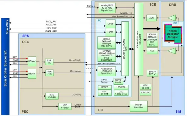
The electronic control system is shown in Figure 11. The SoloHI Power Supply (SPS) receives 28V and relay commands from the spacecraft and provides low voltages to the rest of the instrument. The SoloHI Instrument Module (SIM) contains four electronic cards – the Processor Card (PC), Camera Card (CC), the Detector Readout Board (DRB), and the Detector Interface Board (DIB). The quad detector package is wire-bonded onto the DIB, a rigid-flex circuit board. Eight harnesses (two for each individual sensor) from the DIB are then connected to the DRB, which contains signal conditioning circuitry both to and from the DIB. The CC contains an RTAX2000 Field Programmable Gate Array (FPGA) to control the APS and analog to digital converter (ADC) of the video signal. Two ADC are included, each running at 2 MHz, giving an effective readout rate of 4 Mpixels/sec. Some image processing functions are included in the CC FPGA – (1) image scrubbing to remove the effects of cosmic rays from an image, (2) image summing to increase Signal to Noise and reduce telemetry bandwidth, and (3) partial field readout to reduce telemetry bandwidth and increased cadence.
The PC is the heart of the instrument. The LEON 3FT-RTAX2000 FPGA emulates a SPARC processor and runs code developed by Aeroflex-Gaisler for ESA to control a small instrument - a Remote Terminal Controller (RTC). It runs under the Real-Time Executive for Multiprocessor Systems (RTEMS), V4.10. A board support package from Gaisler supports SpaceWire and GPIO Drivers, memory controllers with support for both BCH EDAC MRAM and Parallel Reed Solomon EDAC SDRAM memory. The RTC code has a few options which have been optimized for the SoloHI application. The software from the SECCHI3 instrument has been ported over to RTOS, which provides a complete set of instrument control functions – including receiving commands from the S/C, sending housekeeping and science packets to the S/C, running a schedule time-line of camera exposures and camera control parameters (exposure time,
4 0 £>M (OR 2O x0 032 2O x0 032 20x0
asa
332 70A MA002 BAxaMB sfy8h182S 209 3A03 00A M18 V 2AJ8 V 130 0..t z03J1e0 XUM QolsnA 70A li8 01. .bno7 IsnQi2 P hUT = >9 3 720 sl-IM 08 00J V2. f 0..t >.Uf rraiuo9 .uA iswo9 noiiibno7 ó >ö
V O 2GVJ 20VJ 39 (OS 2Ox0 MAA02 8AXAhIAB sty8M82S 3A03 200 MOM VII sfy8h18 ,BxtlhlS£ 773 Isntsfnl 8)11,8 h1009 tone 0. £t louno0 1909 ß 1003H
XUhl QdsnA .bno7 Ima 11342 A 88 Sr 2 W S£S20 Is -I JI1noN 8uCSO J09V2.t T3230 320 ony2 sl-IM t 320 VIM 02 33 292 (Sl hJ0 i000 21sS6sii Q0 022 (S) 010 V£.£ 022 (Sry T31USJ V£.£ 008YH N Vtt O08YH 3351 YAJ30 YAJ30 4 339 V80 OAO MST V8S OMO MST m 03 Nreadout coordinates, gain setting, voltage bias settings), acquiring instrument status information, performing lossless and lossy image compression, and cycling the operational heaters according to a Proportional-Integration-Derivative (PID) algorithm to maintain the instrument temperatures to their desired values.
Figure 11. SoloHI Electronics System
7. STRAY LIGHT TESTS
A stray light model of the instrument was fabricated and tested in the stray light chamber at NRL and at CSL. Figure 12 shows the NRL setup of the model on a test fixture. In the image, the front of the instrument is pointing down and to the left. The fixture permits the orientation of the baffles to be set at any angle relative to a collimated light source to simulate the effect of scattering from an object such as the solar array. In Figure 13 the test image for the solar array simulation is shown on the left and the model calculation is shown on the right. The intensity wedge on the left gives the calibrated intensity scale in units of Bo, (mean solar brightness units, a commonly used unit of
solar coronal observations and equivalent to about 4.839 x 1033 erg/s). Table 3 shows the correlation between the image and the model calculation for various surfaces. We found that most of the discrepancies between data and simulation came from the edges of the baffles and a correction to the way that the model treats the baffle edges was necessary. In order to apply the correction on the model, the coating properties of the flat edge surface at the tip of the baffles were changed. Using trial and error and also, for simplicity of implementation, we found that using Lambertian scattering properties on those edges provided a reasonable way to apply a correction to the model. Table 3 shows a problem with two surfaces – glints off the F4 baffle and the I4 baffle. Both of these issues will be resolved for the flight design.
-2'2 12 ?0 5'2 5'0 5'2 -S'0
Figure 12. Stray Light Model On Test Stand. The instrument is mounted on a stand and is pointing down towards the mounting table. The forward baffles are very black and are at the front of the instrument. The reflective side panels surround the interior baffles in the interior of the instrument. The white bracket at the rear of the instrument is holding a test camera.
Figure 13. Comparison of Stray Light Image (Left) with Simulation (Right). The test image is a bigger field of view than the simulation.
IeB6nsI 1-926L BIgcK 0'85 0.54
IeEga6 rg26L BIgcK 5'12
(na
12Ega6 ry26L BIgcK 3.2a 0.88
12eI!uf rg26L BIgcK TI'eT 3'3a
14 r926L BIgcK 3'45 T'1-1
bBgi113!aPfB6n6I BIgcK yuog!ssg 5'40OW
bBgiiELOUfg6n61 Blgcl<yuoq!ssq I-1-8 OW
131i!aPiM!uaEgae V385 43'52 0'22
13r64M!uaEgas V385 Te0'a4 5'e0
E4GI!uf t1385 103110 TO'14
ljsalOD UgUJ6 COg(IUa
pio COu.scf!ou (Dgfg 1 21UJfl) ljgll0 yusl. CO.l.scf!OU (Dgig I 21UJf1) fjgfl0
Table 3. Feature brightness ratio between data and simulation
8. SUMMARY
The Solar Orbiter mission will be the first venture of an imaging instrument outside of the ecliptic plane and
combined with the close encounter with the sun is very exciting. The SoloHI instrument is very mature - the Critical Design Review occurs in September 2013. A compact instrument has been developed that meets all of the
requirements. A new APS detector has been developed and the flight lot has been run and is currently being evaluated, with promising test results. The stray light analysis was significantly more advanced than SECCHI. The analysis has shown that rejection of light being scattered by the solar array onto the instrument baffles is still a significant concern.
ACKNOWLEDGEMENTS
It is a pleasure to acknowledge the sponsorship of this work by the NASA Solar Orbiter Collaboration Project. The NASA SOC project office is a small team headed by the project manager, Haydee
Maldonado, with Carolyn Mariano, the SoloHI instrument manager, Joseph Cerullo, the systems engineer, and Chris St. Cyr, the U.S. project scientist. They are supported by other members of the Heliospheric Division headed by Nicholas Chrissotimos. The ESA project manager for the Solar Orbiter mission is Philippe Kletzkine and the instrument managers are Giorgio Bagnasco and Anne Pacros.
REFERENCES
[1] Müller, D, Marsden, R.G., St. Cyr, O.C., Gilbert. H.R.. “Solar Orbiter - Exploring the Sun-heliosphere connection,” Solar Physics, in press (2013).
[2] Schwenn, R., Marsch, E. (eds.), [Physics of the Inner Heliosphere], Springer-Verlag, Berlin and Heidelberg, (1990).
[3] Howard, R. A., et al., “Sun Earth Connection Coronal and Heliospheric Investigation (SECCHI),” Sp. Sci. Rev.,
136, 67-115, (2008).
[4] Howard, R.A. Moses, J.D., Socker, D.S., “Sun-Earth connection coronal and heliospheric investigation (SECCHI),”
Proc. SPIE, 4139, 259-283, (2000).
[5] Kaiser, M. L., Kucera, T. A., Davila , J. M., St. Cyr, O. C., Guhathakurta, M., and Christian, E. , “The STEREO Mission: An Introduction,” Sp. Sci. Rev., 136, 5-16, (2008).
[6] Vourlidas, A., Lynch, B. J., Howard, R. A., Li, Y, “How Many CMEs Have Flux Ropes? Deciphering the Signatures of Shocks, Flux Ropes, and Prominences in Coronagraph Observations of CMEs,” Solar Physics, 284, 179-201 (2013).
[7] Velli, M., “Nasa’s Solar Probe Plus Mission and Implications for the Theoretical Understanding of the Heliosphere,” Adv. Space Res., 39, 2065, (2012).
[8] Vourlidas, A., et al., “Seeing the corona with the solar probe plus mission: the wide-field imager for solar probe+ (WISPR),” Proc. SPIE, This Volume, (2013).
[9] Eyles, C. J., et al., “The Heliospheric Imagers Onboard the STEREO Mission,” Solar Physics, 254, 387-445, (2009).
[10] Halain, J.-P., et al., “Straylight-Rejection Performance of the STEREO HI Instruments,” Solar Physics, 271, 197-218, (2011).
[11] Janesick, J., Andrews, J.T., and Elliott, T., “Fundamental Performance Differences Between CMOS and CCD Imagers: Part 1,”
Proc. SPIE,
6276, 20, (2006).[12] Janesick, J., Andrews, J., Tower, J., Grygon, M., Elliott, T., Cheng, J., Lesser, M., Pinter, J.. “Fundamental Performance Differences Between CMOS and CCD Imagers: Part II,”
Proc. SPIE,
6690, 1, (2007).[13] Janesick, J., Pinter, J., Potter, R., Elliott, T., Andrews, J., Tower, J., Cheng, J., Bishop, J., “Fundamental Performance Differences Between CMOS and CCD Imagers: Part III,”
Proc. SPIE,
7439, 4, (2009).[14] Janesick, J., Pinter, J., Potter, R., Elliott, T., Andrews, J., Tower, J., Grygon, M., Keller, D., “Fundamental Performance Differences Between CMOS and CCD Imagers, Part IV,”
Proc. SPIE,
7742, 9, (2010).[15] Janesick, J. R., Elliott, T., Andrews, J., Tower, J., Pinter, J., “Fundamental Performance Differences of CMOS and CCD Imagers: Part V,” Proc. SPIE, 865902, 35, 2013.