Nuclear Engineering Department Massachusetts Institute of Technology
Cambridge, Massachusetts August, 1960
Final report on contract DSR 8246, performd for the Pratt and Whitney Aircraft Division of the United Aircraft
Corporation
I
r~J
DYNAMICS AND CONEROL OF NUCLEAR ROCKET !NGINICS
by
H. P. Smith
A. H. Stenning
Page 24, line 2:
Page 26,
equation
Page
37,
Page
43,
2 lines
(3~12):
line
8:
"Po2
IO2
below
"H
should be
"a a"
should be
it
-
a
c="
"4
0Pressure
... "should be "H. Pressure
equation (4-1):
"P
x
*
1
+
P*"
I
x
should
be "P
x
1+ P*
x
Page
44,
equation (4-2):
"G
T
"should be
2p
Page
45,
9Page
4.7,
equation
(4-4):
equation
(4-6):
should be
"G IT
"
"1G
integral sign for
i
is omitted
should
be
n=
fe n*(t)dt
0
Page
54,
line
4:
" p*t
should be
"pPage 69, figure 11:
"from pole at ... " should be "from zero at 000"'
Page 85,
lines 1 & 3:
"a,"
should
be
"
-r
*
Page 88, equation (4-48): The equation should be
PC*
G
(9
-
*)dt
+
G
(G
-G*)
j
"Po2/vro
2
-Page 89, line 13:
"The
limit of
Gi*..."
should be
"The limits of G*"
Page 113, lino 9t
"as
rapid a response as the
..should be
"as
rapid a response as possible. The
...
"Page 141, equation (1-5) & (1..6):
""" and "p'"
"'
Tp
= " and " Tp
=
a
should be
3rd
line
from
bottom:
"'resigned" should be
"'designed"
Page
144,
line
11:'
"'O =
29.7
...
Page 153,
"
should be
"oc
=
29.7 ... "
equation (11.17):
should be
(1/2)(1.06)
fsurface,
entrance) + T(surface,exiti
T(surface, exit)
Page 165, line 12:- Between lines 11 and 12 inject,
"'to core inlet pressure"
by
1. P. -smith*
A. H. Stenning
ABSTRACT
The dynamics and control of a nuclear rocket engine with bleed turbine or topping turbine pump drive is studied. Throughout the thesis, the
attempt is made to retain a physical understanding of the mathematics and to attain results which can be applied generally to present concepts of nuclear rocket engines and which do not depend on a specific design. In accordance with this purpose, identification is made of the important characteristics of each component, and its behavior is described by the
simplest possible model consistent with reasonable engineering accuracy. A system of non-linear equations, based on a lumped parameter analysis is derived to describe the dynamic performance of the engine.
A stability criterion for uncontrolled operation, formulated from linear approximations of the dynamic equations, is derived. It is shown that the engine is stable to small perturbations if the temperature
coeffi-cient of reactivity of the empty core is negative. The stability criterion is not dependent upon the magnitude of positive reactivity feedback that results from increase of hydrogen (propellant) density in the core. A parameter is defined which measures the margin of stability. A more general and thereby more complex criterion of stability is presented.
An analysis of the transient response is made and is verified by analog computer simzlation of the non-linear dynamics. The system is remarkably insensitive to changes of the major coefficients and is able to safely
A5 00C. Fellow, Department of Nuclear Engineering, M.I.T.
*Assistant Professor of Nuclear Engineering, M.I.T.
i
withstand large perturbations. It is shown that the asymptotic response depends directly on the mechanical inertia of the turbopump and that
reduction of the thermal inertia of the core does not improve the response The insensitivity and sluggishness is explained from physical considerations.
A feedback control system is proposed and found satisfactory by analytic investigation and analog simlation. The results of simlation of controlled rapid transition from a low power level to full power opera-tion is presented. A successful method of startup is proposed and
investigated with the aid of an analog computer. Response and methods of control at full power are presented. The topping turbine system is
favorably compared with the more common bleed turbine system.
The work described below was carried out at M.I.T. under the sponsorship and with the financial support of the Pratt and Whitney Division of the United Aircraft Corporation. The authors would like to thank Mr. P. Bolan for his valuable
suggestions, Professor Elias Gyftopoulos for his advice, Professor Henry Paynter for his assistance in the operation of the Analog Computing Facility, and Mr. Yotaka Yoshitani for his assistance
in many phases of the analysis.
TABLE OF CONTENTS
Page
Section I: IN1TRODUCTION . . . . . . . . - - - -. . - 1
A. Nuclear Rocket Proposals . . . . . . . . . . . . . . 1
B.
A Comparison of Chemical and Nuclear Power for Rocket
Engines . . . .
. .
.. .
.
.
2
C. Possible Dynamic Problems of Nuclear Rockets
. . . .
5
D. Problems of Control . . . . . . . . . . . . . . . . . 6
E. General Attack . . . . . . . . . . . . . . . . . . 8
Section II:
DESCRIPTION OF THE ROCKET . . . ...
.. ..
.. .. .
A. Overall Design . . . . . . . . . . . . . . . . .11
B.
A Comparison of the Bleed Turbine and Topping Turbine
Systems . . . .
11
C. Component Description . . . .
*.
.. ..
.
. .. .
14
Section III: DERIVATION OF THE DYNAMIC EQUATIONS
. . . .
17
A. Lumped Parameter Analysis . . . .
17
B. Fluid Inertia and Compressibility . . . . 17
C. Neutron Kinetic and Precursor Eguations . . . .
18
D. Thermal Equation . . . . . . . . . . . . . . . . . . 20
1.
Core Temperature Variation at Steady State . . . 202. Core Pressure Variation at Steady State . . . . . . 22
3.
Expression
of the Mass Rate of Flow as a Function
of the Core Inlet Stagnation Pressure and
Maxiim
Surface Temperature
. . . .
23
4.
Formulation of the Time-Dependent Maximum Surface
Temperature as a Function of the Neutron Density
and Core Inlet Stagnation Pressure . .. . . .. . .24
E. Reactivity Equation . . . . . . . . . . . . . . .
25
F.
Temperature Control Equations . . . . . . . . . . . . 261. Bleed Turbine System .. . . . . . . 28
2. Topping Turbine System with Control Valve in Front of the Turbine . . . . . . . .. . . . . . .. . . .
31
3. Topping Turbine System with Control Valve after the Turbine . . . . . . . . . . . . . . . 34
H. Pressure Control Equations . . . . . . . . . . . . . . . 37
I. Scaling of Equations . . . . . . . . . 38
Section IV: ANALYSIS OF THE DYNAMIC EQUATIONS . . . . . . . . . . 43
A. Open Loop Stability- .... . . . . . . . . . . . 43
1. Development of Linear Equations . . . . . . . . . . 43
2. Elimination of the Precursor Equation .. . . . . . 45
3. Stability Analysis of the Open Loop by means of the LaPlace Transformation .. . .. .*. . . .. . . 46
4. A Physical Basis for the Stability Criterion . . . . 48
5. A More General Statement of the Stability Criterion. 52 B. Open Loop Response . . . . . . . . . . . .. .. . .. .
60
1.
Location of Roots . . . . . .. . . . . . . . .. . 602. Prediction of Open Loop Response . . . . . . . . . . 65
3. Analog Simulation of Open Loop Response . . . . . . 72
4. Discussion of Open Loop Simulation . . . . . . . . . 80
5. Variations of Open Loop Response . . . . . . . . 81
C. Closed Loop Stability . . . . . . . . . . . . . . . . . . 86
1. Temperature Controller Limits . . . . . . . . . . . 86
2. Pressure Controller Limits . . . . 90
D. Closed Loop Response . . . . . . . . . . . . . . . . . . 100
1. Comparison of Root Location for Open and Closed Loops 100 2. Comparison of Pressure-Valve Response of the Suggested Turbopump Drives . . . . . . . . . . . . . 101
Page
Section V:
NUCLEAR
ROCKET ENGINE STARUP . . . . . 107A. Proposed Method . . . . . . . . . . . . . . . . . . . . 107
B. Proposed Model . . . . . . . . . . . . . . . . . . 108
C. Results of Analog Simulation . . . . . . . . . . . . . . 109
Section VI: TRANSITION TO FULL POWER . . . . 112
A. Limits of Feedback Signal Amplification . . . . . . 113
B. Results of Simlation . . . . . . . . . . . . . . . . . 114
C. Results of Coefficient Variation for Full Power Transition . . . ... . . . .
*.
..*.
. .. . .. .. .114
D. Transition to Full Power Using an Oversized Turbine .
117
E. A Comparison of Transition for the Two Turbopump Systems 117 Section VII: FULL POWER CONTROL . . . . . . . . . . . .119A. Response at Full Power . . . . . . . . . . . . . . . . . 119
B. Full Power Control with Constant Control Rod Position. . 120 C. An Optinim Thrust Program for Nuclear Rockets . ... . 122
D. Possible Malfunctions at Full Power . . . . . . . ... 123
Section VIII: SUMIARY AND CONCLUSIONS ... ... . 125
A. Stability . . . . . . ..
.
.. ... 125B. Uncontrolled Response .. . ... 128
C. Controlled Response . . . . . . . . . . . . . . . . . . 130
D. Startup . . . . . . . . . . . . . . . . . . . . . . . . 131
E. A Comparison of the Dynamics of the Proposed Turbopump Configurations . . . . . . . . . . . . . . . .. . .. . 132
F. Recommendations for Further Study . . . . . . . . . . . 133
List of Symbols . . . . . ... .. 134
Appendix I: Calculation of Constants . . . . . . . . . . . A. Calculation of Time Constants Associated with Fluid
Inertia and Compressibility . . . . . . . . - . . . B. Calculation of Temperature and Pressure Time Constants C. Computation of Reactivity Coefficients . . . . . . . . D. Specification of Arbitrary Design Parameters . . . . . Appendix II: Appendix III: Appendix IV: Appendix V: Appendix VI: Appendix VII:
Relation Between the Mean Core Temperature and Maximum Surface Temperature . . . . . . . . . . . .
Pressure Ratios Across the Turbine and Control Valve of the Topping Turbine System, Case I . . . Pressure Ratios Across the. Turbine and Control
Valve of the Topping Turbine System, Case II Development of the Dynamic Pressure Equations Under the Assumption of Choked Flow in the
Topping Turbine . . . . . . . . . . . . . . . .. Formation of the Open Loop Stability Criterion by Application of Routh's Technique . . .. . . . ..
Photograph and Description of the Analog Computer Facility . . . . - - - - . - - - . . .
148
154158
163
168
171
Appendix VIII: Pressure Response to Valve Motion at ConstantTemperature a. .. . . . . . . . . -. - -
174
A. Bleed Turbine SystemB. Topping Turbine System, Case I C, Topping Turbine System, Case II
Bibliography . . . . . . . . . . . . . . . . - - o . .. .
181
Biographical Sketch . . . . . . . . . . . . . . . - . . . 183 vii Page136
136
14o
143
145
-.ILIST OF FIGURES 1.0
2.
3.
4.
5.
6.
7.
8.
9.
10. 11.Schematic Diagram of a Nuclear Rocket Engine . . . . Coolant Flow-Chart . . . . . . . . . . . . . . . . .
Reactivity as a Function of Pressure and Temperature Stability in the Temperature-Pressure Plane . .
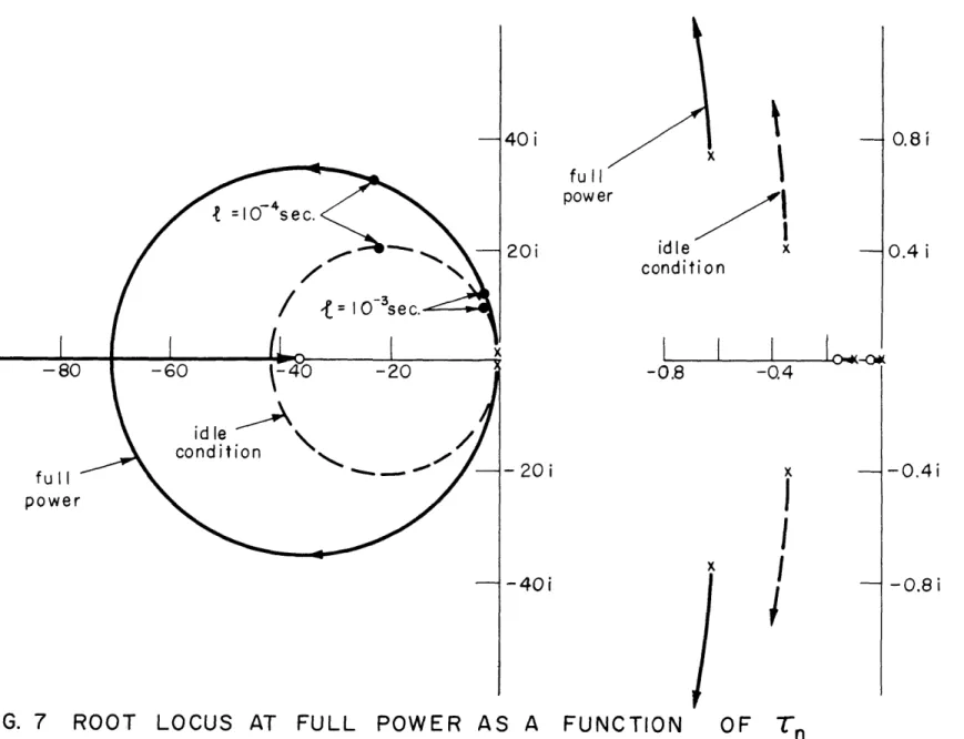
Stability Margin in the Temperature-Pressure Plane Root Locus at Idle Condition as a Function of / n .
Root Locus at Full Pover as a Function of * n
Root Locus as a Function of Power Level . . . . . . Root Locus at Idle Condition as a Function of T Root Locus as a Function of . . . . Root Locus as a Function of '7 . . . . . . .p
. 0 . . .0
12. Root Locus as a Function of Thermal Inertia ( )for a Simple Reactor System . - . . . . . . . . . . . . . .
13. General Analog Flow-Chart . . . . . . . * . .
14. Detailed Analog Flo-Chart
...
0 . 015. Open Loop Response . . . - - . - - . . . . . . . . . . . . . 16. Open Loop Response (continued) . . . . .0 . . . . 17. Root Locus as a Function of Temperature Controller, Gi*
18. Root Locus (Bleed Turbine) as a Function of Pressure
Controller, G3 * . . . . . . * * . . . . . . .
19. Root Locus (Topping Turbine) as a Function of Pressure
Controller, G3 * . . . . . . . . . . . . . . . . . . 20. Root Locus (Bleed Turbine) as a Function of Pressure
Controller, G2
*
. . . . . . . . . . . . . . . . . . . . . .21. Root Locus (Topping Turbine) as a Function of Pressure
Controller, G2* . 0 0 0 0 0 0 0 0 . . . . 22. Root Locus (Bleed Turbine) as a function of G3* for various Values of
G/G3*
. . . . . . . . . . . .viii
98
Page 1213
27
49
53
62
63
64
67
68
69
73
75
76
79
84
91
93
94
96
97
. . . . ..
-. .23. Root Locus (Topping Turbine) as a Function of G
various Values of G2*/G3* ' ' ' ' ' ' ' ' ' ' ' ' . . . ' ' 99
24. Pressure-Valve Response . ... . . .. .-... .. .. 105
25. Power Density and Pressure During Startup . . . . . . . . . 110
26. Temperature and Pressure During Startup . . . . . . . . . . 111
27. Normal Transition to Full Power . . . . . . . . . . . . . . 115
28. Rapid Transition to Full Power . . . . . . . .
..
. . 118LIST OF TABLES
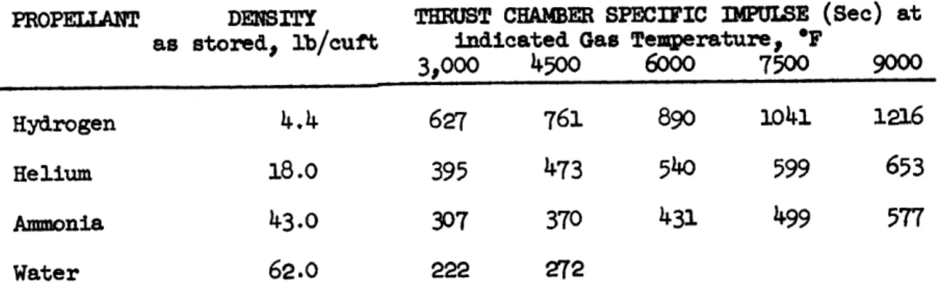
Page I. Specific Impulse Values and Gas Properties of
Propellant Combinations . . . . . . . . . . . . .
II. Specific Impulses for Various Nuclear Propellants . . .
III. List of Coefficients and Constants . . . . . . . . . .
IV. Time Constants Associated with Fluid Inertia and
Compressibility . . . . . . . . . . . . . .
V. Symbols and Constants Employed in the Analog Flow-Chart
9
10
18
77
A. Nuclear Rocket Proposals
During the last years of World War II, technological innovations were presented that greatly enhanced the possibility of space exploration. The German V-2 rocket provided a convincing proof that long-range rockets could be built and operated. Moreover, the United States introduced the first application of nuclear energy by exploding the atomic bomb at Alamo-gordo, New Mexico. It was obvious that a marriage of these innovations should occur. Projects, such as gaseous core reactors and atomic bomb blasts (Project Orion), were and are being proposed to use the huge nuclear energy directly. Practical considerations relegate projects of this sort to the next decade. However, more conventional means of using the power of the nucleus for rocketry have been proposed in the literature as early as 1948 by Shepherd and Cleaver
The United States Government has instigated Project Rover at the Los Alamos National Laboratory in New Mexico to develop a nuclear powered rocket(2). The primary result of the project has been the construction and operation of a nuclear 'ocket core, which has been dubbed Kiwi-A after the
flightless bird of Australia.0,04) Undoubtedly the U.S.S.R. is also moving forward on a similar project
(5).
Both countries have veiled their work in secrecy, so that little factual knowledge can be found in the literature. Nonetheless, independent work has been done and published as well as some publication by companies who are sub-contracted to the Rover Project. Theavailable information indicates that the first nuclear rocket will have a graphite-uranium core that will be used as a high power density heat exchanger.
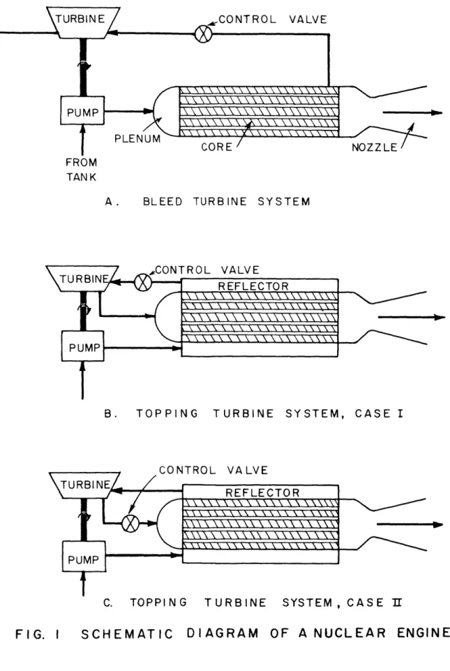
In this design, (See Figure 1) the propellant is stored as a cryogenic fluid in a large tank that comprises the bulk of the entire rocket. During operation, the propellant is pressurized in a pump, heated *The numbers in parentheses refer to the bibliography.
-2-to high temperatures as it passes through the core and is accelerated in a nozzle. Some or all of the propellent gas drives the turbine which provides the power needed by the pump. Various turbopump drive configura-tions have been proposed. Two are considered in this thesis.
B. A Comparison of Chemical and Nuclear Power for Rocket Engines The superiority of nuclear fission energy as the primary power source for rocket propulsion rather than the energy released by chemical combustion of oxidizer and fuel can be shown by considering the kinematic performance of a single stage, rocket vehicle. It is assumed that the rocket rises vertically with zero drag and constant specific impulse in a constant gravitational field. The basis of comparison is the vehicle velo-city achieved when the engine has stopped. This is termed the burnout
velocity. That engine which yields the highest velocity for the same ratio of payload weight to initial weight is adjudged superior.
Under the conditions imposed by the above assumptions, the following expression can be derived for the burnout velocity.(2)
vb Igo
n
m - goth(1~1)
mb
where vb = velocity relative to Earth at burnout
I = specific impulse of the propellent jet relative to the rocket
mb mass of the rocket at burnout m = mass of the rocket at takeoff
0
t = time to burnout
If one assumes that chemical and nuclear rockets would operate for the same time to burnout, then it is clear that the highest burnout velocity will be attained by that vehicle which has the highest value of Igo ln mo .
First, a comparison is made of the specific impulse of the two types of engines and then the entire expression is considered.
If the expansion of the propellant in the nozzle is adiabatic and isentropic, the following expression for specific impulse can be derived.
(6)
2 / Z T 1
-go -1)-R M-
-(1-2)
where = ratio of specific heats R = universal gas constant
To= nozzle stagnation temperature
M = molecular weight of the propellant PR = pressure ratio across the nozzle
The value of is approximately the same in either type of engine.
p
Since graphite has good mechanical properties for temperatures up to 5500*R, the propellant stagnation temperature at the exit of the core is in the same range as that produced in a chemical rocket combustion chamber. The same pressure ratios are possible. Therefore, that engine which utilizes a propellant of lower molecular weight has a greater specific impulse.
Molecular combination of the oxidizer and fuel molecules must occur in the combustion process. This combination is not required in the nuclear rocket engine since the fission of uranium provides the energy rather than chemical combustion. The molecular weight of the nuclear rocket propellant can be as low as two if pure undissociated hydrogen is used. The lowest molecular weight that has been attained in chemical rockets has been nine. It does not seem possible to reduce this value significantly.( It is evident that a nuclear rocket, utilizing hydrogen, will have a specific impulse more than twice that of a chemical rocket.
-4-The phenomenon of dissociation of molecular species further adds to the advantage in specific impulse of the nuclear rocket. Since the reactor core is temperature limited rather than energy limited, as is the chemical rocket, dissociation can occur without lowering the stagnation temperature. In chemical rocket combustion chambers, dissociation causes a drop in stagnation temperature and has the net effect of lowering the
specific impulse.
Specific impulses of chemical and nuclear rockets are presented in Tables I and IU. These figures demonstrate convincingly that nuclear engines can clearly double the highest specific impulses attained with present fuels. Tormey(7) has shown that an upper limit of approximately
420 seconds exists for any chemical fuels that may be considered.
Although the nuclear rocket can develop a higher specific impulse, it does so at the expense of carrying a heavier engine and structure to the burnout altitude. Thus, the parameter of merit suggested earlier (Ig o in E ) is not as large as might be expected from consideration only
mb
of specific impulse. The core and reflector, which are major components of the nuclear engine, greatly increase its weight, while the added structural weight is primarily that of the large tanks needed to contain low density liquid hydrogen.
If we assume that the specific impulse of a nuclear rocket is double that of its chemical counterpart, the mass ratio, M of the nuclear
rocket rust be equal to or greater than the square root of the mass ratio of a chemical rocket if an equivalent or superior burnout velocity is to be attained. If a burnout velocity of 30,000 ft/sec is desired, a chemical rocket whose specific impulse is 400 see would require a mass ratio of 10.2. This value approaches the maximu that can be attained with any practical
(39
whose
specific impulse was 800 sec and whose mass ratio was 3.2. This ratio is possible even with the heavier engine and structure. Future developments should permit even higher mass ratios for nuclear powered rockets.(l4)C. Possible Dynamic Problems of Nuclear Rockets
The decoupling of power produced and the flow rate of propellant in a nuclear rocket engine is an inherent and fundamental feature not common to the dynamics of chemical rocket engines. It is obvious that if more power is required in a chemical rocket, then more fuel, thus more propellant, mtst be brought to the combustion chamber per unit time. A nuclear rocket can conceivably operate at any power level, including a
catastrophic one, without any propellant being present . This is the primary reason for its high capabilities and inherent dangers.
Atomic energy has been successfully used in reactors for almost two decades. The problems of control have been examined, the solutions applied and found satisfactory. Conventional reactors are easily controlled because rapid changes of power level are not necessary. They are rarely, if ever, made prompt ci'itical.(8) However, in a rocket engine, slow change of power level causes a large wastage of propellant, making the rocket inefficient to the point of being useless. If nuclear power is to be satisfactorily applied to rocketry, rapid, but controllable, charges in power level must be possible.
In order to achieve this, the reactor must be prompt critical. The power level would then have an e-folding time measured in milli-seconds or less. This precludes instantaneous control by mechanical motion of control rods, reflectors or poisons. For short periods of time when the core is prompt critical, the rocket must be inherently stable without controls, if it is to be used with any reasonable degree of safety.
-6-If the core has a prompt negative temperature coefficient,(8) the problem of dynamic instability will not be as severe, but it is not necessarily solved.
An increase in the amount of hydrogen, an excellent neutron
moderator, into an under-moderated system reduces the fast leakage, thereby increasing the reactivity. The phenomenon would not exist in the rocket reactor if it were over-moderated rather than under-moderated, but this cannot be avoided. The ratio of moderator atoms to fissile atoms must be small in order to insure a high power density. Furthermore, only graphite, a poorer moderator thaz hydrogen, can maintain satisfactory mechanical properties at the high temperature of a nuclear rocket. Thus, the dynamic problem is further complicated by positive reactivity feedback induced by increased hydrogen density in the core. Felix discussed the problem but did not include it in his analysis of nuclear rocket dynamics.(11)
The above phenomenon can conceivably cause an instability in a nuclear rocket engine using a gas turbine, driven by heated and compressed propellant, to drive the propellent pump. An increase in system pressure
increases the density of hydrogen in the core, causing a positive react ivity. If uncontrolled, the core power level would increase as would the turbine output power. Therefore, the initial increase in pressure can cause a
further pressure increase. The system would then be unstable.
Consideration imzst also be given to instabilities introduced by equipment malfunctioning, such as pump failure, stoppage in a coolant
channel, erosion of the graphite, etc..
D. Problems of Control
The proposed control system mst be capable of making corrections of thrust and specific impulse while the engine is in operation. Further-more, it mist not only be a stable system, but mzst yield a rapid response
without dangerous overshoot. Feedback control of the core temperature and pressure should be able to meet these criteria. It will be examined for
two zones of operation. An initial startup zone is also investigated.
Zone 1: Subcritical to intermediate power (idling condition)
Since introduction of hydrogen to the bare core yields a positive reactivity, the reactor can be taken from subcritical to supercritical without control rod movement. As the power level of the reactor increases,
following the introduction of hydrogen, the turbopump mist be started. At the intermediate power level, the turbopump should be self-sustaining.
A core pressure and temperature of 200 psi and 1000OR should be sufficient for this operation. Since the control mechanisms are not needed for the original reactivity increase, they will be positioned for the intermediate power level. A negative temperature coefficient of reactivity should insure that the intermediate state is attained rather than a catastrophic one.
Zone 2: Intermediate to full power
It is unlikely that the control rod setting corresponding to full power would also correspond to an intermediate power level. Some part of the change from intermediate power to high power will requaire control rod motion.
Once the idling condition has been achieved, the rocket propellent tank furnishes the propellant. In order to utilize the tank hydrogen as effectively as possible, the time between idling and full power should be
reduced to a miniimum. Therefore, the control mechanisms must be repositioned as q~uickly as possible without causing dangerous overshoots of pressure
-8-Zone
3:
Full power control
Wang(10) has saown that the thrust of a nuclear rocket should be varied for an optimum burnout velocity. Even if his program for thrust should prove impractical, some change of control mecbanisms will probably be necessary during full power operation to achieve the desired trajectory or to counteract the effect of carbon erosion or other component wear.
E. General Attack
In Section II, a more detailed description of the rocket is given. Two turbopump systems are presented and compared, although not from a
dynamic point of view. The design is chosen only to provide approximate values of parameters. The analysis is general and applicable to any nuclear rocket which uses a reactor as a high power density heat exchanger.
A model, based on the design parameters of Section II, is
proposed in Section III. Equations are derived for the model which describe the transient behavior of the engine. In order to keep the analysis general, a lumped parameter model is used, and the number of equations is kept to a minimum. A physical understanding of the system is thereby maintained for the analytic work as well as the solutions obtained by analog computers.
A linear analysis of the equations of Section III for both the controlled (closed loop) and uncontrolled (open loop) engine is presented
in Section IV. From this analysis, conclusions can be drawn concerning stability, speed of response, damping characteristics and oscillatory
behavior. The turbopump systems are compared from a dynamic point of view. The various zones of operation are discussed in Sections V, VI, and VII. The d-scssion is based primarily on the results of the solution of the dynamic equations by a Philbrick Analog Computer.
Finally, conclusions and suggestions for further work are presented in Section VIII.
TABLE I*
SPECIFIC IMPULSE VALUES AND GAS PROPERTIES OF PROPELTANT COMBINATIONS. OXIDIZER Hydrogen Peroxide Hydrogen Peroxide Nitric Acid Nitric Acida Nitric Acid Oxygena Oxygena Oxygen Oxygen Flourine Flourine Flourine FUEL Gasoline Hydrazine Gasoline Aniline Ammonia Alcohol Gasoline Hydrazine Hydrogen Amonia Hydrazine Hydrogen
PC
=
500
Tel *F4830
4690
5150
5100
420
5560
5770
5370
4500
7224
7940
5100
PSIA M 2119
25 21 22 2218
9
19
19
9
/
1.20 1.221.23
1.23
1.24
1.22
1-241.25
1.26
1.33
1.33
1.33
248
262
240
235
237
259
264
280
364
306
316
373
P= 1000 PSIA Is273
288
255
258
285
261
290
308
400
337
348
410
a Liquid propellant systems now being used in the U.S.Te = Combustion Chamber Temperature, * F
M = Average molecular eight of combustion products
= Ratio of molar specific heat at constant pressure and volume. * Taken from Reference 7.
-10-*
TABLE II
SPECIFIC IMPULSES FOR VARIOUS EUCLEAR PBRPELLAIqTS
PROPELLANT Hydrogen Helium Ammonia Water DENSITY as stored, lb/cuft
4.4
18.0
43.0
62.0
THRUST CHAMBER SPECIFIC IMPULSE (Sec) at indicated Gas Temperature, *F
3,000
4500
6000
7500
9000
627
395
307
222761
473
370
272
890
540
1041
599
499
1216
653
577
Section II: DESCRIPTION OF THE ROCKET
A. Overall Desiga
Figure 1 is a schematic diagram of the rocket engine, which is similar to one presented by Stenning and Smith (32). Licuid hydrogen is stored in insulated tanks and pressurized by helium. Leaving the pump at high pressure, the hydrogen regeneratively cools the nozzle and reflector and then enters the plenum for the main pass through the core. A small amount of the hot propellent gas is bled off from the gas mixing region in
front of the nozzle and drives the turbine. A valve between the mixing region and turbine determines the flow to the turbine and thus provides system pressure control. After leaving the turbine, the gas exhaust is
used for thrust recovery in small auxiliary nozzles. This system is referred to as a bleed turbine system.
Rather than using a small amount of gas at high temperature to drive the turbine, the entire flow at a lower temperature could be used to drive a topping turbine. In this system, the hydrogen is regeneratively heated in the nozzle, reflector and outer regions of the core, then passes through the turbine and enters the core for the main pass. The flow is controlled by a valve i front of or immediately behind the turbine. The
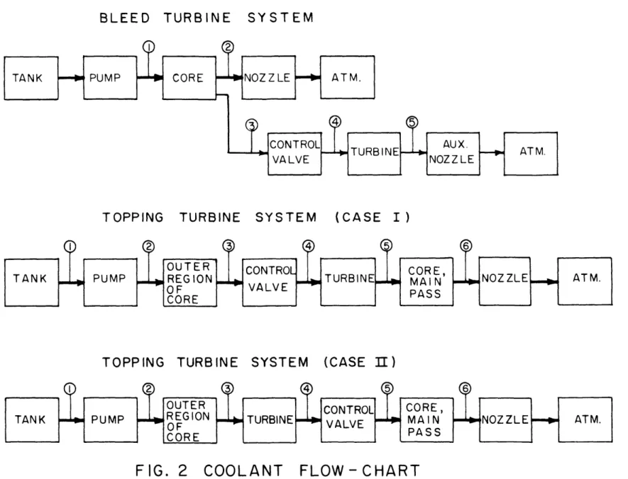
flow charts of these systems are shown in Figure 2.
B. A Compari7son of the Bleed Turbine and Topping Turbine Systems Both turbopimp drives have been used in chemical rockets and proposed for nuclear rockets. Although the bleed turbine drive has been preferred in the past, the topping turbine has two advantages.
(1) Lighter weight.
Because of greater flow through the turbine, less work is extracted per unit flow. The blade speed is less than the bleed turbine, and there
12 CONTROL VALVE PLENUM CORE NOZZLE FROM TAN K
A. BLEED TURBINE SYSTEM
B .\T O P P NCO N T R O L V A L V E
TURBINREFLECTOR
PUMP
B. TOPPING TURBINE SYSTEM, CASE I
CONTROL VALVE
C. TOPPIN G TURBINE SYSTEM , CASE If
TOPPING
TURBINE
SYSTEM
(CASE
I)
TOPPING
TURBINE
SYSTEM
(CASE II)
FIG. 2 COOLANT
C,)
-le-is no need for speed reduction gears between turbine and pump. This results in a lighter system.
(2) Slightly higher specific impulse.
Although thrust recovery nozzles are used for the bleed turbine exhaust, there is a reduction in the specific impulse attained due to the large
pressure drop in the turbine. Since all propellant passes through the main nozzle in the topping turbine system, there is no loss in specific
impulse-for the same nozzle stagnation pressure.
C. Component Description (1) Core
Various authors have proposed that the rocket core should be a graphite matrix, impregnated with uranium-235.(13, 14, 15) Graphite is a good neutron moderator and possesses excellent mechanical and thermal properties at high temperatures. The atom ratio of carbon to uranium-235 is taken as 500. Reynolds( 16) has investigated atom ratios from 150 to 1500 with corresponding buckling of
25.5 x 10⁻⁴ cm-2 to 17.5 x 10- 4cm2.
The atom ratio choice of 500 ensures criticality and retention of graphite thermal and mechanical properties in the matrix. Lower values of atom ratio would jeopardize these properties.
Various methods of core construction have been proposed..(l3,1)4) 5) One of the most feasible is a right circular cylinder approximately 5 ft in diameter and length, composed of a homogeneous graphite-uranium matrix in which 1/4 inch holes are drilled parallel to the axis for coolant flow. A void coefficient (coolant volume fraction of total core volume) of 30%
seems suitable. This design would insure criticality, good heat transfer characteristics, and high thrust and specific impulse.(l7)
Erosion of the graphite along the coolant channels by the hot gas might cause severe damage to the core. It has been proposed that the
channels be clad with tungsten or a ceramic, which would introduce critical-ity and heat transfer problems. Since it should be possible to stay below a critical erosion temperature, the cladding proposal is not considered in this paper.
(2) Reflector
A reflector around the core flattens the power density and lowers the necessary critical mass. Either pure graphite or beryllium oxide is suitable. Most papers(14, 15) on this subject favor a six inch radial reflector of BeO, with 10' void for regenerative cooling.
(3) Reactivity Control
Although control rods have been mentioned in the previous chapter, they present serious problems of cooling and of pressure seals for the drive mechanism. For a high power density rocket reactor, reflector control should be satisfactory and alleviates the problems inherent in control rods. The design offered by Newgard and Levoy(15) is suitable.
(4) Pump
A centrifugal pump pressurizes the propellant. A volume of 10 ft 3 and length of 3 ft is chosen to compute charging time and acoustic time of transit.
(5) Turbine
A multi-stage, axial-flow bleed turbine and a single-stage, axial flow topping turbine provide the power needed to drive the pump in the various turbopump systems proposed. The time constants mentioned in (4) are computed by setting the volume and length equal to 20 ft 3 and 4 ft,
-
16-(6)
Controls
The reflector (reactivity control) and control valve (flow
control) are positioned according to feedback signals based on core
temperature and pressure respectively.
Since choking exists in the nozzle,
the core exit temperature can be computed from pressure and flow
measure-ments rather than from thermocouples
hich are too slow for satisfactory
rocket engine control. The stagnation and static pressures are measured in
the standard manner.
Of course, many parameters are measured in flight,
but we
are concerned only with those associated with control.
As mentioned in Section I, the design has been chosen only to
provide approximate values of the parameters necessary to describe the
dynamics of the system. A more detailed design than presented above would
reduce the generality
of the analysis. Some of the details are mentioned
only for purposes of description and have no effect on the derivation of
the dynamic equations.
These details will be obvious in the derivation,
which is presented in Section III.
SECTION III: DERIVATION OF THE DYNAMIC EQUATIONS A. Lumped Parameter Analysis
In order to make the analysis simple and meaningful, a lumped parameter model is proposed, in accordance with the philosophy mentioned in Section I. Under this assumption, one value characterizes the value of a parameter throughout the system. Of course, the assumption is not strictly true, but the simplicity and resultant physical intuition justify the
inaccuracies introduced. Furthermore, a distributed rocket core temperature study of Yoshitani(12) has shown that the lumped temperature dynamics of the rocket core deviate little from those of distributed temperature.
Since the design is chosen only to provide approximate values of constants which appear as coefficients in the lumped parameter equations, the coefficients are assigned a range of values and the effect of the
variation is investigated.
B. Fluid Inertia and Compressibility
The compressibility of hydrogen is considered only to derive steady state equations of fluid flow and heat transfer in the engine. The transient effects of fluid inertia and compressibility are neglected. Consequently, the resultant time constants are associated with core heat
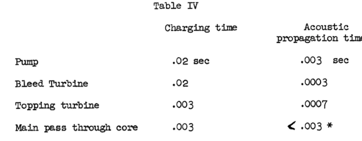
capacity and turbopump inertia and are of the order of seconds. (See Table
3
at the end of Section III).If fluid inertia and compressibility are considered, constants arise which are associated with the time necessary for charging the components with fluid and for acoustic propagation. Since the fluid properties and component configurations are known, these constants can be calculated and appear in Table 4. Their actual calculation is presented in Appendix I, as well as various other constants which appear in the course of the derivation of the dynamic equations.
-18-Table
rV
Charging time Acoustic
propagation time
Pump
.02 sec
.003
sec
Bleed Turbine .02
.0003
Topping turbine .003 .0007
Main pass through core .003
<
.003 *The constants in Table 4 are orders or magnitude smaller than those time constants associated with the thermal inertia of the carbon-uranium matrix or the mechanical inertia of the turbopmp. For this reason the high and low frequency transients of the fluid dynamics can be decoupled. This has been pointed out by Felix.( Since the high frequency dynamic behavior
is not peculiar to the nuclear rocket engine, but occurs in many applica-tions, only the low frequency fluid dynamics are considered, with the justified assumption that charging and acoustic transients will have no effect on the low frequency system.
C. Neutron Kinetic and Precursor Equations
The standard neutron kinetic and precursor equations are employed.
(8)
dn
+.(
-
kC(3-2)
* Since the Mach number in the core is always less than one, the acoustic time constant is less than the charging time constant.
where:
n = neutron density
= reactivity
= total fraction of delayed neutrons
= precursor group fraction of neutron yield = effective neutron lifetime
= precursor group delay constant
01 = precursor density
The effective neutron lifetime,
1,
is computed by Westcott's method.Although his teclhnique applies primarily to well moderated, thermal reactors, the results, presented in Table 3, agree with more sophisticated computa-tions of Sams and Newgard.(14,15)
The precursors diffuse through the graphite rapidly at the high temperature of a rocket reactor. Many diffuse into the coolant channels and are swept out of the core before releasing delayed neutrons. The net dynamic effect is a reduction of from the experimentally measured value of 0.065. Since no data is available in the literature on this subject, an effective value of .0050 is assigned. A part of the analysis of the dynamic behavior is an investigation of the effect caused by a change in the
precursor yield fraction.
Precursor groups which decay more slowly have less chance of contributing neutrons to the core than the faster decaying groups. The values of are assigned accordingly and presented in Table 3. For analytical work a standard technique is adopted whereby all precursors are assumed to behave as one group with average properties.(8 )
Although all six groups can be simulated on the analog computer, the same accuracy is obtained by using two fictitious groups whose constants are derived by approximating the exact reactor transfer function.(2)
D. Thermal Equation
1. Core Temperature Variation at Steady State
Stenning(17) has shown that the following relation exists, provided the power density is constant and the heat transfer-friction analogy is applicable:
T
S2
(3-3)
TO
01
'0 2
+1---01where N Stanton number at
T = maximum surface temperature
T = stagnation temperature of the coolant at the entrance to the core
T02 " " " exit of the core
f friction factor
L P length of the coolant channel D = diameter of the coolant channel
In the region of interest, a constaat poler density distribution causes a higher maximum surface teerature than a sinusoid distribution for the
4ftL 02 (7
same values of and T .
)
Since the temperature of the carbon uranium matrix is the limiting factor, the assumption of a constant power density is ore conservative and is adopted throughout the derivation. The Prandtl number of hydrogen is approximately oneunder all conditions of temperature and pressure. Thus, the heat transfer-friction analogy is valid and equation (3-3) is applicable for temperatures in the rocket core.
Hydrogen enters the core as a pressurized cryogenic fluid and reaches the core exit at the highest possible temperature thast the core can withstand. Conseguently,
T.1
T
0 201
01
For this reason, equation (3-3) can be accurately approximated by
T
s
2
(
3-4)
T 0 2 ( -'
--If the friction factor, f, is assumed constant, the maximva surface temperature of the core is proportional to the coolant exit temperature.
T
<
T02
(3-5)
The average temperature of the graphite-uranium matrix is proportional to the maximm surface temperature. This can be shown by solving the tim independent heat conduction equation as shown in Appendix II.
2. Core Pressure Variation at Steady State
By assag that the vall shear stress in the core coolant
channel increases linearly with distance along the channel, Stenning (17) has shown that the following relation exists between inlet and outlet stagnation pressures:
PO01
2(3-6)
P0
2
X-7
-LV
-where = ratio of specific heats M = Mach number
subscripts 1, 2 = Entrance, outlet of the channel. The assumption of linearly increasing vall shear stress has been justified by the agreement of the above result with numerical integration of the differential equations of one dimensional compressible gas dynamics.
In rocket operation the Mach number at the entrance of the channel i small and equation (3-6) can be approximated to within 1% by
2M
P01
1
+ /
2M
21+
D
)
022
1
2
)A2
(3-7)
2
2
In the same paper, Stenning points out that if the expansion in the nozzle is isentropic and adiabatic, which is an excellent approximation, the Mach number at the exit of the channel is constant so long as choking exists in the throat of the nozzle. This is the situation in all cases of interest. Thus, the inlet and outlet stagnation pressures are proportional.
P01
<P
0 2(3-8)
3. Expression of the Mass Rate of Flow as a Function of the Core Inlet Stagnation Pressure and Maximum Surface Temperature
If fluid compressibility and inertia are neglected, as mentioned in subsection B, the mass flow rate, W , is constant throughout the system at any given instant of time. (The mass flow used for turbine drive in the bleed turbine system is less than 2/ of the total flow rate and is neglected in the following formulation.) It is convenient to replace
the flow rate by an expression involving only temperature and pressure. Since choking occurs in the nozzle throat, the following condition exists:
__t_ = constant (3-9)
PO
where T = stagnation temperature at the throat
ot
P0 = stagnation pressure at the throat
The expansion of the propellant in passing from the core exit to the throat is assumed adiabatic and isentropic. Consequently, /0- Il /' = 7 and Tb o = To.
By substituting the above equalities into equation
(3-9),
we can show that
the flow-rate is proportional to the ratio,. / and To2are eliminated by substitution of the expressions of (3-5) and (3-8), and the following expression is formed.
ej
c><
01
(3-10)
S
4. Formlation of the Time-Dependent Maximum Surface Temperature as
a Function of the Neutron Density and Core Inlet Stagnation
Pressure
Conservation of energy dictates that the heat generated within
the core by fission must either be removed by the coolant or be stored in the form of thermal energy. Energy transfer from the core by radiation and
conduction is negligible in comparison to the convective cooling of the propellant as it passes through the core. The time derivative of the
conservation statement yields a power balance which is stated below.
time rate of change power released heat carried away
of thermal energy by fission . by the coolant
of the core per unit time
The power released by fission is proportional to the neutron density. If a constant of proportionality, K1, is introduced, the above statement can be expressed as
dT
MC
-
K
n
n
-
.c
(T
-T
)
dt
/p02 co01
where M = mass of the graphite-uranium matrix
C = specific heat of the graphite-uranium matrix
It has been shown in Appendix II that the ratio of the maxinrum surface
temperature, T., to the average core temperature, T , is constant. Consequently dT can be replaced by T a dTs In the third term of
Ts dt
the power balance, To, is insignificant in comparison with T0 2 and is
neglected. The proportionalities (3-10) and (3-5) are substituted for 4-'a
and T0 2. Thus, the heat carried away by the coolant per unit time is
proportional to Po1 .F If a second constant of proportionality, K2,
is introduced, the above equation is expressed as
MC
T
dT
K
n
- K2
P1
(3-11)
T
8dt
1
2
017TS
The constants K, and K2 are eliminated by a scaling technique presented in
subsection I of this section. The single constant formed by this technique is calculated in Appendix I and presented in Table 3.
We have now succeeded in expressing the time-dependent maximum surface temperature as a function of the neutron density and inlet stagnation pressure. In accordance with a lumped paramenter analysis, the maximu
surface temperature and core inlet stagnation pressure are defined as the charateristic parameters of the rocket engine pressure and temperature distributions.
E. Reactivity Equation
Reactivity is a function of core temperature, hydrogen density, and control rod position (or reflector position, depending on design). Control rod position offers no problem of formulation, since the position is expressed in units of reactivity.
A Fermi-age model of neutron interaction is assumed in order to calculate the reactivity effect of core temperature and hydrogen density.
-26-Reactivity decreases linearly with increase of the square root of core tem-perature if the hydrogen density is constant. The primary effect is the
increase of thermal diffusion length as a result of decreased absorption at higher temperature. The effect is explained in detail in Reference
9,
pages487- 489.
Hydrogen is an excellent moderator. Increase of hydrogen density reduces the fast leakage proportionately and increases the reactivity. Since density is proportional to the ratio of pressure to temperature, the density in the core is proportional to . These considerations lead to
a reactivity equation of the form
T
+
01(3-12)
S
where C = control rod reactivity
Of C= bare core temperature coefficient of reactivity
= hydrogen density coefficient of reactivity
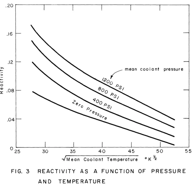
Figure 3 i*s a plot of reactivity as a f'unction of the square root of temperature for various values of pressure. o' and are calculated
from this graph. The calculation is presented in Appendix I and is in good agreement with that of Newgard and Levoy.(15)
-< = 0.001 *R 1/2
of =
0.3
*R/psi F. Temperature Control EquationsIntegral feedback is employed for temperature control. Since the square root of temperature is measured, the feedback signal is computed directly from the square root rather than temperature itself. The control
30 35 40 45 50 Coolant Temperature
-/Mean
FIG. 3
REACTIVITY
AS A FUNCTION
OF PRESSURE
AND
TEMPERATURE
.20 .16 .12 0 0 A) .08mean coolant pressure
.04[
O 25
55
-28-response cannot be instantaneous, a first order lag is introduced between the desired rod setting and the actual setting. Equation (3-13) indicates the formation of the signal; equation (3-14) indicates the first order lag.
t
G - dt
(3-13)
Cdt
(3-14)
where / = desired control rod reactifity G = integral signal amplification T = desired maximum temperature
= time constant of control rod motion
The control rod cannot respond rapidly to proportional feedback control because of its large inertia. It is shown in later chapters that
integral control is satisfactory. G. Pressure Equation
1. Bleed Turbire System
The primary principle in the derivation is conservation of energy which is expressed as
time rate of change of
kinetic energy of the = turbine power (OT) - pump power (Op)
rotating machinery
(3-15)
Kinetic Energy = IN2 (3-16)
2
where I = Moment of inertia of the rotating parts
0,
7TO*
(4-/
where
7T
= turbine efficiency4T flow rate through turbine
PR
=
pressure ratio across the turbine noszles T m stagnation temperature in front of turbine#p
-t
(3-18)
where PT = tank storage pressure
7
pump
efficiency
p density of hydrogen in pump
The problem is to reduce equation (3-15) to terms involving only the core inlet pressure, the core surface temperature, and a valve setting.
In order to eliminate the turbine flow rate, the valve characteristics are examined. The valve is in front of the turbine and controls the
pres-sure to the turbine. The valve flow equation can be expressed as
Roy
/(3-19)
where T stagnation temperature in front of the valve Po3 = stagnation pressure in front of the valve P04 w stagnation pressure behind the valve Av M area of the valve
~-1-
= a fanction of the indicated pressure ratioThat point of a core coolant channel from which the propellant is bled to drive the turbine is tized by the design. Consequently, %3 may be assumed
proportional to the coolant exit stagnation pressure, Po2, and T o3 'my be assumed proportional to the exit stag ntion temperature.
-30-The flow through the bleed turbine is choked.
_ _17_-__
-
W
constant (3-20)AT is the cross-sectional area of the turbine nozzles. The stagnation temperature on either side of the valve is the same. Consequently, division of the above two eqations yields
AT P o4 0o4)(2l
-)
(3-21)
03
03
A unique value of P 0/P 3 is determined by each valve setting and the
following fictitious valve setting may be defined:
Y(Av) = P04/Po3 (3-22)
If the proportionalities of (3-5) and (3-8) are employed, the flow-rate through the turbine is expressed by
r (3-23)
The pressure ratio, PR, across the turbine nozzles remains constant because of choking in the nozzles and in the exhaust ducts. If turbine efficiency is constant, the turbine power is proportional to /AJ T since the
stag-nation temperature remains constant across an adiabatic valve Incorpora-tion of the proporIncorpora-tionalities (3-5) and (3-23) yields the following
expression for the turbine output power.
76
<>
(3-24Similarly, a reduction of the pump power equation can be made. The hydrogen density in the pump and the pump efficiency are constant. It has been shown that the flow-rate through the pump is proportional to P
8 Finally, the tank storage pressure is neglected in comparison to