EcoGRAFI
2nd International Conference on Bio-based Building Materials &
1st Conference on ECOlogical valorisation of GRAnular and FIbrous materials June 21th - 23th 2017 Clermont-Ferrand, France
MECHANICS OF STRAW BALES FOR BUILDING APPLICATIONS
T. Lecompte*, A. Le DuigouUniv. Bretagne Sud, FRE CNRS 3744, IRDL, F-56100 Lorient, France *Corresponding author; e-mail: thibaut.lecompte@univ-ubs.fr
Abstract
During the last decades, straw bales have seen an increasing interest for building insulation and even for the construction of small load-bearing straw houses, especially in view of the need to seek low environmental footprints. Up to present, very few studies are available concerning the mechanical behaviour of straw bales in buildings. Nowadays hybrid timber and straw methods are taking over from simple load bearing structures. There is a lack of knowledge about the mechanical contribution of straw in such structures, as in load bearing configuration. This study aims at investigating the mechanics of straw bales by carrying out experiments on batches of substantial numbers of bales and observing their anisotropic behaviour. Compression models are proposed to estimate their behaviour in a load-bearing wall, which lead to some recommendations in terms of bale densities. The cross-comparison of experimental results shows that, in the density range 90-110 kg/m3, the elastic and strength characteristics are similar whatever the position of the bales (laid flat or on their edge). The mechanical behaviour of the straw bales is found to be influenced by the arrangement of straw and strings. When laid flat, the bales exhibit a particular type of deformation under single compression leading to a constant perimeter. In this position, the mechanical properties are controlled by two factors: (1) the packing density, induced by the machine during the baling process, and the elasticity and creep of the links; (2) the solid volume fraction of straw wisps, conditioned by the agronomic parameters and the pressure level in the baler.
Keywords:straw bales, building, stiffness, anisotropy, compression, granular packing
1 INTRODUCTION
In Europe, about 40% of natural resources are currently used in the construction and building industry [Brandt 2004]. Agricultural by-products can be used as a resource to reduce the environmental footprint of building materials and also provide supplementary income for harvesters.
Apart from representing an agricultural by-product basically used for animal feed or litter, straw can be re-grown annually, and can be considered as a local building material with very few processing transformation steps and low fertilizer input. Over the past twenty years, straw is being increasingly used in alternative ways, as bio fuel power generating plants or construction material. Straw-bale building materials have developed from both the architectural and scientific points of view [King 1997] (Fig. 1). Construction rules regarding insulating materials have even been recently validated in several countries, such as in France [RFCP 2014] and the U.S.A. [Hammer 2013]. In the United Kingdom, some low-cost bale house concepts have been developed [Beadle 2009] and are now on the market [Guardian 2015]. Up to now, these rules and concepts mainly consider straw as an insulating filling and not as a load bearing material. Hybrid timber and straw systems are currently taking over from the historic load bearing
methods, but a better knowledge of the mechanics of straw bales should permit to optimize the use and amount of timber that is the more expensive material, and even to improve straw baling process in the aim of load-bearing building. Year 1996 1998 2000 2002 2004 2006 2008 2010 2012 2014 2016 Nu mber of pu blic ation 200 400 600 800 1000 1200 1400 1600
Figure 1 Evolution of number of publications in Elsevier® with keywords (straw + building)
Straw bales are generally made directly on the cereal field, just after the grain harvest. Three principal
formats exist: round bales, small oblong bales of low to medium density (50-150 kg/m3) and large oblong bales with high densities (> 150 kg/m3). For building, the straw bales are generally laid flat, by hand. Thus, the small bale is the most commonly used format, with a weight of barely more than 15 kg and maximal dimensions of approximately 40x50x100 cm.
During harvesting of the cereal crop, the combine harvester collects the grains, and pours straw windrows onto the field. After an optional tedding step, baling consists of picking up the windrows and pressing the straw wisps together. In small balers, the wisps are oriented by the feeding screw, being pressed in the direction of the long axis and then linked together (Fig. 2). During the baling process, the main pressure is applied according to the long axis of the bale and is maintained at the desired compaction state by strings (generally two or three strings, made of thermoplastic polymer).
Figure 2: operating principle of small square straw baler [Hahn 2009, Renaud 1967]
Straw bales are currently considered as an insulation filling material for construction applications, but more and more self-builders and even municipalities are attracted by load-bearing structures made of straw bales. Such structures are made up of vertical walls of straw bales laid flat and associated with horizontal timber frames. The timber frames and straw walls are held together with tensioning wires that also pre-stress the straw bales. This structure is sometimes supplemented with wooden bracing. The coating of such constructions can be made up of render (plaster, lime or earth) or timber cladding. The building generally has a maximum of two floors (ground+1), with a light roof. This technique raises some new questions about the stiffness, creep and stability of straw-bale walls and, more generally, the influence of straw-bale mechanics.
Until now, studies of straw building materials have been almost exclusively concerned with their hygro-thermal characteristics. The durability of straw insulation materials against moisture has been
demonstrated [Thomson 2014, Lawrence 2009] and their hygro-thermal properties are now well known [Goodhew 2004-O’Dogherty 1989]. However, there are only very few studies on the mechanical behaviour of straw subjected to a compressive load. Some studies have considered the compressibility of straw as a raw material in silos or during a compression process [Mani 2004, Leblicq 2015] or the mechanical behaviour of individual stems [Nona 2014]. Nona et al. [Nona 2014] have investigated the compression characteristics of bulk straw, fitting its compression and stress relaxation behaviour with models such as the Maxwell model. Studies of the mechanical behaviour of straw bales used as a building material are always associated with a given construction technique. For example, Arnaud et al. [Arnaud 2009] studied a specimen containing a combination of load-bearing timbers and straw bales reinforced by nails and straps, while Rakowski and MacDougall [Rakowski 2009] and Vardy and MacDougall [Vardy 2006] considered straw-bale plastered walls. To our knowledge, there is a lack of available data in the literature about the compression behavior and properties of individual straw bales. The only articles on this subject [Ashour 2011, Arnaud 2009] deal with a low number of samples combined with a narrow range of densities, which is hardly representative of the natural variability of such a building material. In addition, the main identified weakness in straw-bale construction is the highly variable geometry and density of the bales arising from the baling process.
The aim of the present study is to establish a baseline on compressive strength and elasticity characteristics (behavior and properties) of small straw bales, using two different batches with densities varying from 65 to 115 kg/m3 processed by two different straw balers, supplemented with literature data [Ashour 2011, Rakowski 2009]. The target application is the use of wall filling as a load-bearing material, with the further goal of understanding the levers for assessing straw building technology.
The anisotropic behaviour is also studied by loading some bales laid flat and others laid on their edge. The analytical models of compression tested here are based on the mechanics of granular media, allowing us to explore the relationship between permanent loading and deformation for the current load-bearing technique.
2 MATERIALS AND METHODS
2.1 Material
The straw making up the bales comes from wheat stems harvested in South Brittany, France. The two batches described in Table 1 display a large range of densities, allowing us to investigate the influence of both density and process on the mechanics of straw bales.
Batch 1 was cropped in the summer of 2013 and batch 2 in 2014, in different fields, and by two different farmers. The wheat sowing density was the same: 280 seeds/m². The cost of the bales was around 1.5€/unit. The density distribution of each batch is given in Fig. 3. Building regulations for straw [RFCP 2014] used essentially for insulation applications in wooden structures recommend bale densities of between 80 kg/m3 and 120 kg/m3, which therefore includes our samples. Batch 1 densities are globally too low for Auger Pressure control Bale length control Knotters Needle s
building applications, but a large range of density is interesting to highlight the correlation between physical and mechanical properties of straw bales.
Table 1: Description of straw bale batches
For load-bearing straw bales, the recommended densities are generally equal to or higher than 120 kg/m3. The density of the straw bale is determined by the straw baler used. Variability in geometry and density is one of the main issues that slows down the widespread application of straw buildings. Indeed, as illustrated in Fig. 3, most of the variability arises from the differences between processing machines, while a marked variability is also observed within each batch (coefficient of variation of 6% in each batch).
Figure 3: Density distribution of the two batches of straw bales
Only one or two recent modern straw-baler brands (for example the 1800 series of Massey Ferguson) are known to process small straw bales with well controlled high densities. Nowadays, most of the small straw balers in activity are more than twenty years old and can barely reach a density level above 100 kg/m3. The density and moisture of the wisps also varies between batches: even if both batches come from wheat that was sowed at 280 seeds/m², the first batch was derived from organic farming, with no chemical treatment, whereas the second was provided by a conventional farmer who also used some stem-shortening agent. This can lead to differences in the stem cross-section, particularly affecting the amount of woody core in the inner part [Leblicq 2015]. Furthermore, the first batch was drier (about 9% humidity, measured by heating in a drying oven until weight stabilization) and the second was wetter (about 20% of humidity), due to the variable weather conditions during harvesting and storage. This has led to a difference in the wisp densities and therefore the bulk density of straws (Table 2).
Another explanation can be put forward: the second batch was more tightly compacted into the baler, and then tied with polypropylene strings, whereas the bales
of batch 1 were tied together with sisal strings. Therefore, the two batches were subjected to different loading paths (baling process and creep at rest). As a result, the wisps of the second batch may have undergone more creep, by flattening, buckling or ovalization of their cross-section [Leblicq 2015]. In this way, the solid volume fraction of the wisps in batch 2 could be increased.
2.2 Experimental device and data processing
The bales were directly loaded by single compression under a hydraulic press, at a controlled displacement rate of 1 mm/s. Each batch was split into two equal parts: one for compression in flat position and the other for compression in edge position, to study the anisotropic behaviour (Fig. 4).
Figure 4: The compression device and the two different configurations. (bottom) edge, at the beginning of a
test; (top) flat, with a strain of 0.77
A typical stress-strain curve is given in Fig. 5. Due to the high levels of deformation, the strain is computed as the true strain :
𝜀 = ln (ℎ0ℎ) (1)
Even if the curves are similar in the edge and flat position, the shape of the specimen shows a very different evolution during compression: bales laid flat undergo intense deformation that can be correlated with the initial string length. These bales maintain a rectangle-oblong shape and, according to the transversal deformation measurements (as also observed by Ashour et al. [Ashour 2011]), the sum of height plus length of the bales can be assumed to remain constant. While this appears to be surprising for a material, a bale should be considered rather as a system produced by the packing of straw wisps, which are pre-stressed in the bale-length direction by the strings. In the flat position, the true stress can then be written:
𝜎 =𝑤𝑖𝑑𝑡ℎ.𝑙𝑒𝑛𝑔𝑡ℎForce =𝑤.(𝑙0+ℎ0−ℎ)F (2) In the case of bales laid on their edge, the length remains constant, so the stress always corresponds to the force over the initial area.
Figure 5: Typical curve of cyclic compression on a bale, irrespective of loading direction (edge or flat)
From these observations, arbitrary parameters are chosen (Fig. 5) to compare the bale properties and investigate a possible correlation between bale density and mechanical characteristics: a stress parameter 0.1 corresponding to the stress level when the strain reaches 10%, and a rigidity parameter E representing the elasticity tangent modulus during the initial load. This elasticity modulus is calculated as the maximum slope during the first load. It should be noted that this modulus is representative of the linear part of the curve between at least 6% and 10% of strain for each batch and position. The stress level 0.1 is chosen because it is close to the point where the curves switch from a linear to a nonlinear region. This choice also allows us to reduce possible perturbations of the device setting. Furthermore, in the case of load-bearing straw bales, the usual approach is to pre-strain the bales by a few percent with pre-tensioning belts to allow a satisfactory setting of the bales. Secondly, it ensures that the wall is stiffer against vertical loading. Thus, operations can be carried out on the roof without causing any critical deflection or differential deformation of the walls. According to this practice, the bales are in a pre-stressed state, and their behavior should correspond more closely to deformation with a few percent strain.
3 RESULTS AND INTERPRETATION
3.1 Compression behaviour
Globally, the stress-strain curves can be divided into different regions: i) a narrow curve foot corresponding to the setting of the device to fit the sample, ii) a quasi-linear elastic phase that continues to around 10% strain, and then iii) a quasi-linear hardening phase (Fig. 5). The straw bales are very ductile and no breakage occurs during compressive tests whatever the loading direction, and even with true-strain near 80% (Figs. 4 and 6).
On Fig. 6, the curves of edge and flat loading are compared for two levels of density (≈ 62 kg/m3, ≈ 98 kg/m3). The curves have similar shapes, whatever the load or density of the bale.
Large hysteresis loops are observed, characterizing a highly viscous behavior. This is a well-known aspect of the behaviour of plant products [Nona 2014, Peleg 1980], and could be of interest in a para-seismic context, since it enables the storing of deformation energy during an earthquake. However, when the bales are unloaded and kept at rest under ambient conditions, they even recover their initial shape after a few minutes, highlighting a time-dependent elastic
behaviour as already observed by Ashour et al. [Ashour 2011]. As a result, this composite material, consisting of compressed straw pre-stressed by strings, behaves in an exclusively visco-elastic manner. This behaviour is very unusual in terms of particle compaction, and is probably due to an association of highly elastic straw wisps [Leblicq 2015] with the pre-stressing links.
Figure 6: Compression curves in edge and flat positions, at two different densities: 62 kg/m3 and 98
kg/m3
3.2 Compression parameters
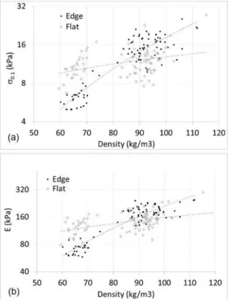
Figs. 7a and b show the evolution of stress at 10% strain and the elastic modulus, respectively, as a function of straw bale density for the two configurations (laid on edge and laid flat). In the density-range 80-100 kg/m3, these data show that the stiffness and strength in both bale configurations are of the same order and even slightly higher in edge position. This is advantageous from a thermal point of view: laid on the edge, the thermal flux is perpendicular to the straw wisps, and the thermal conductivity will be lower than in the flat position, as already shown with other agro-resources [Picandet 2015]. This could represent some saving of resources for given thermal and mechanical performances. However, considering the lower density range (60-70 kg/m3), a slight difference can be observed between the two positions pointing out the anisotropic behaviour.
The best model for fitting mechanical parameters versus density is a power law, corresponding to the compaction model proposed by Jones [Jones 1960]. Table 2 reports the mechanical properties estimated with Jones’ compression model. The parameter a (Table 2) is usually called “compressibility”, even if it does not correspond to the thermodynamic definition of compressibility. In Jones’ model, a material with a higher value of compressibility displays a higher volume reduction under a given pressure. As a comparison, Tronet et al. [Tronet 2014] found a “compressibility” of 0.323 on dry hemp shiv in a compression die, a value that corresponds to stiffer packing than in the present study.
Results are observed to be highly scattered in the flat position (R² =0.16), but show a more acceptable fit with the compression model in edge position (R² =0.84). It is noteworthy that no data are excluded and that specimen variability is also responsible of the scattering of results. In flat position, the variability of parameters at a given density is much higher than their evolution with density (due to variation between the two batches). The density in itself does not appear as an appropriate variable to explain the variance of mechanical parameters.
Straw bales loaded on their edge have characteristics that are more strongly dependent on density. In fact, in the edge position, straw is mainly loaded parallel to the wisp direction as the balling process tends to orient the wisps and the bale strings maintain a constant cross-section. The wisps have less degrees of freedom than in the flat position. A direct correlation between compactness (i.e. density) and mechanical properties can then be observed because the solid section of the straw wisps is directly loaded. In the case of flat position, the compression is more difficult to relate to the mechanical characteristics and should depend on the stress-strain history of the straw entering the baler and after: as seen on Fig. 2, the straw is compacted along its length at a level of compression that is controlled as it enters the baler. Thus, the stress/strain path depends on this initial compaction, on the nature of the strings and the creep behavior of the straw wisps in the bale. All of these parameters influence the overall shape of the wisp cross-sections, the initial solid fraction in the packing of wisps and, as a result, the subsequent compression behaviour of the bale in flat position. The results for the flat position configuration are discussed in more detail in section 3.3.
Figure 7: (a) Stress at 10% strain and (b) tangent elastic modulus as a function of initial density of the
specimens.
Table 2: Best fitting models for the mechanical characteristics of straw bale versus initial density. Elastic modulus and strength are expressed in kPa,
densities are expressed in kg/m3.
3.3 Compression mechanisms in flat position
When compressed in the baler, the straw is compacted along the length of the bale in successive layers that are orthogonal to this direction. At the end of the process, the strings maintain a given compaction state in these layers. A certain stress remains, even after relaxation. This phenomenon can be observed when the strings are cut: the bale relaxes elastically, but only in the long direction. This explains why the strings stay under tension when the pressure is applied flat, whereas they buckle when the bale is loaded in the long direction (not shown here).
This conformation of wisps in layers perpendicular to the flat loading means that they are able to deform during compression. Actually, this deformation should depend on the inter-wisp voids that exist within the bale. This void space, or inter-particle porosity, represents the volume of the bale minus the place taken by the wisps. This void volume depends not only on the density of the bale, but also on the apparent density of the wisps themselves, conditioned by the original wheat stem properties: density (linked to the core structure [Leblicq 2015]), moisture and transverse properties (flattening, ovalization, creep and elasticity). The density of the wisps can be evaluated from the bulk density of the straw when the bale is untied: the denser the wisps, the denser the bulk packing.
Since the bulk density is different for the two batches (Table 1), a compression model is required that considers the bulk state. Cooper and Eaton [Cooper 1962] proposed such a model. Unlike Jones’ model [Jones 1960], the approach adopted by Cooper and Eaton is not only phenomenological, but also uses statistical laws to describe the compression as previously studied theoretically by Seeling and Wülf [Seeling 1946]: the compaction of particle beds is known to occur in three steps: rearrangement, deformation of particles, and, in some cases, breakage of particles. From a physical point of view, the Cooper and Eaton model provides pressure levels at which each phenomenon is likely to occur, and can give a density target for straw bales used for load bearing. Above a certain density threshold, the straw wisps achieve almost all their deformation and the stiffness of the bales will then increase more rapidly.
This model leads to good correlations for ground straw [Mani 2004] and hemp shiv [Tronet 2014]. Here, it is rewritten in terms of density, assuming that no particle breakage occurs, in terms of 0.1 versus the density of the bale at 10% strain, 0.1:
1 −𝜌𝑏𝑢𝑙𝑘 𝜌0.1
1 −𝜌𝑏𝑢𝑙𝑘𝜌𝑆
⁄ = 𝑎 exp (−𝜎0.1𝑘1) + (1 − 𝑎) exp (−𝜎0.1𝑘2) (3) where bulk is the bulk density and S is the specific density of the straw wisp cell-walls, here taken as the cellulose density (~ 1500 kg/m3), while a, k
1 and k2 are
constants ; k1 (resp. k2), in kPa, is the pressure at which
the rearrangement (resp. the particle deformation) is most likely to occur. 0.1 is the density of the bale at 10% strain, as calculated from Eq.2:
𝜌0.1= 𝜌0(𝑙0+0.1ℎ0)(ℎ0−0.1ℎ0)𝑙0ℎ0 (4) where 0, h0 and l0 are initial characteristics of the bale.
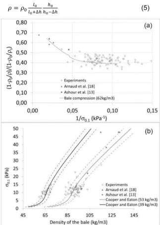
Fig. 8a shows the experimental data, taking the bulk densities of Table 1. Some experimental data from the literature [Ashour 2011, Arnaud 2009] are added to enlarge the range of density investigation.
It should be noted that Eq. 3 must also be valid during the compression test on each bale. To validate this assumption, the compression curve of a bale of 62 kg/m3 (batch 1) is drawn on Fig. 6a. To achieve this, the curve is taken above 10% strain, the cycle loops are removed, and is also calculated from Eq.2:
𝜌 = 𝜌0𝑙0+∆ℎ𝑙0 ℎ0−∆ℎℎ0 (5)
Figure 8: (a) Experimental data and compression curve of a bale with an initial density of 62 kg/m3, in relation
to the Cooper & Eaton modelling parameters; (b) Experimental points and fit with Cooper & Eaton model, using a=0.42, k1=0.84 kPa and k2=49 kPa. The
dashed curves indicate the model variation due to ±5% scatter in bulk density
This curve fits well with the experimental data (Fig. 8a). The parameters used in Cooper and Eaton’s model are computed from this curve with the least squares method. Values of a=0.42, k1=0.84 kPa and k2=49 kPa are found, giving a correlation coefficient R²=0.83 for batch 1 and R²=0.55 for batch 2. The value of parameter k2 obtained from the experimental data implies that the deformation of wisps will occur with the highest probability at around 49 kPa. It is difficult to correlate this value with the strength of straw stems. From a mechanical study of single specimens [Leblicq 2015], the mean flexural yield stress of the cell-wall can be estimated at between 17 MPa and 66 MPa, depending on the stem source area. In a bale, the stress is distributed within the packing, and the loading on each single wisp is very different. Furthermore, the straw wisps themselves are already subject to strain in the baler and at rest. Therefore, it is very difficult to relate these two studies. The value of 49 kPa corresponds to a density ratio /bulk of around 2.15. Therefore, with a bulk density of 55 kg/m3, the target value of density for straw bales should be 118 kg/m3 to minimize deflection under loading. This value is consistent with the density currently advised for load bearing by self-builders, i.e.: about 120 kg/m3. The parameter k1 of Cooper and Eaton’s model is very low compared to the usual values for bio-based materials
[Mani 2004, 24]. It may correspond to the pressure value at which the rearrangement step is likely to occur. This rearrangement is actually achieved during the baling process.
The experimental points of Figs. 8a and 8b are supplemented with the data of Ashour et al. [Ashour 2011] and Arnaud et al. [Arnaud 2009]. It can be observed that the model with a bulk density of 53 kg/m3 yields results close to the literature data points, except for one point. Other studies should be carried out on higher bale densities to confirm this trend. Fig. 8b also shows a high sensitivity to the bulk density of the straw. The model curves for a bulk density variation of ± 5% are drawn on Fig. 8b. These curves cover 86% of batch 1 and 73% of batch 2, suggesting that controlling the stress/strain path of the straw is a very important lever for conditioning its subsequent mechanical behavior.
3.4 Correlation between rigidity and
0.1From the experimental data, we can observe a correlation between rigidity and strength (Fig. 9). The best correlations between these two parameters for flat and edge positions are:
𝐸0.1,𝑓𝑙𝑎𝑡= 11.8 𝜎0.1,𝑓𝑙𝑎𝑡 (6) 𝐸0.1,𝑒𝑑𝑔𝑒= 11.4 𝜎0.1,𝑒𝑑𝑔𝑒 (7) Eq. (6) and (7) are very close to Hooke’s law (i.e. 0.1=0.1 E), showing a slight increase of rigidity between the initial state and the linear behavior region, between 6% and 10% strain.
Figure 9: Elasticity modulus versus stress at 10% strain
3.5 Vertical behavior in a wall, the case of self-bearing constructions
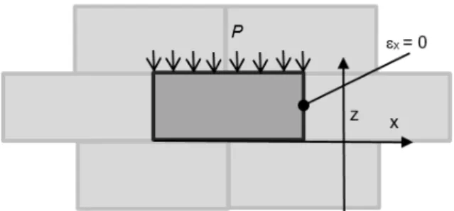
When laid flat in a wall (the most common position for insulation in self-bearing construction), each bale is confined by its neighbors, leading to the boundary conditions given in Fig. 10. In the case of a small-scale ground floor house with 6x6 m² floor space and a light roof (zinc or stainless steel), the linear load q can be assumed to be around 2 kN/m.
Under these conditions, we can write the 3D elastic problem as follows:
𝜎̿ = 2𝜇𝜀̿ + 𝜆 𝑡𝑟(𝜀̿)𝐼̿ (8)
And:
−𝑃 = (2𝜇 + 𝜆) 𝜀𝑧 (9)
where P is the vertical pressure on the wall, while and µ are the first and second Lamé coefficients, respectively. In the transverse plane of the bale (x, z), the Poisson ratio in compression is derived from Eq. 2 or Eq.5:
𝜈𝑧𝑥= −𝜀𝑥 𝜀𝑧 = ℎ0/𝑙0 (10) This parameter is correlated with the bale shape. Thus, it is not an intrinsic parameter of the material. In fact, each bale must be considered as a system, composed of more or less pre-stressed straw and the links that maintain this stress.
Figure 10: A bale contained in a wall and its boundary conditions
The relation between pressure on the wall and vertical deformation of bales can be derived from (9) and (10):
𝜀𝑧= −𝑃𝐸(𝑟+1)(𝑟−2)𝑟(𝑟−1) = −𝑞𝐸(𝑟+1)(𝑟−2)𝑤𝑟(𝑟−1) (11) where r is the aspect ratio of the bale (r=l0/h0), w the
width of the bales and q the linear load on the wall (kN/linear metre). This equation shows that the bale shape is a parameter that plays a role in controlling the wall stiffness: when the bale is in the flat position, a high slenderness ratio gives a stiffer wall. Then, owing to equations 3, 4, 6 and 11, it is possible to estimate the vertical deformation of a wall submitted to a linear load q.
For example, let us assume straw bales with an initial density of around 100 kg/m3, and a bulk density of 53 kg/m3 with dimensions wxhxl=0.48x0.38x0.9 m3. As pointed out in the introduction, load-bearing straw walls are pre-stressed by belts, to improve the cohesion and vertical stiffness of the bales. Let us consider a pre-stressing of 1%. Ignoring the dead weight of the straw bales making up the wall, the load required to reach 1% strain can be approximated by considering a linear behavior for the first loading of the bales until 10% strain. For bales of 100 kg/m3, the density and stress at 10% strain can be calculated with Eq.3 and Eq.4: 0.1=106,6 kg/m3 and 0.1=29,9 kPa. The pressure P and the linear load q that must be applied by the pre-stressing belts follow from Eq.11, i.e.: P=15.6 kPa and q=7.58 kN/m.
Now, considering the dead load of a light roof to be around 2kN/m (zinc or stainless steel), it is possible to estimate the vertical strain of the wall under this load, by assuming that the elastic modulus is close to E. In this case, we find a strain z=-2.5 10-3 q (q in kN/linear metre), leading to a permanent strain of 0.5% which does not exceed the limit for loss of linearity of straw material (Fig. 6). This calculation does not take into account the eventual presence of wood in the corners or the contribution due to coatings.
4 CONCLUSION
The aim of the present study is to gain a better understanding the mechanical behaviour of small straw bales, and identify the levers that might improve their use for building. For this purpose, an experimental study was carried out. The behaviour of the straw bale is found to be different if the bale is loaded on its edge or laid flat. For low densities, the bales laid flat are
clearly stiffer than on their edge. Around 80-100 kg/m3, the stiffness is equivalent in both configurations, and even slightly higher in edge position. When laid flat and loaded in uniaxial compression, the shape of a bale under deformation is controlled by the string length: the perimeter of the bale remains constant.
The density of straw bales laid flat is not the only key parameter, and we should also take account of the apparent density of the wisps composing the bale, as well as the bulk density of the straw. The key parameter is then the ratio of bulk density over straw density, which characterizes the overall compaction state and solid volume fraction of the wisps.
The shape of the bales, more particularly their slenderness, will influence the stiffness of a load-bearing wall made of straw: a high aspect ratio gives a greater stiffness.
By applying the model of Cooper and Eaton, the deformation of wisps is found to be effective for a density ratio o/bulk of around 2.15. This value corresponds to a critical compaction state, for which there is an optimal balance between the applied pressure in the baler and the stiffness of the bale. The interaction between the baling process, the mechanics of straw packing and bales needs to be investigated further, particularly by developing the approach of Leblicq et al. [Leblicq 2015] and Nona et al. [Nona 2014] applied to individual stems and straw packing. This approach should allow us to determine the entire loading path of the straw, from the crop field to the wall, by studying its compressive and relaxation behaviour.
5 REFERENCES
[Arnaud 2009] Arnaud L, La Rosa C, Sallet F, Mechanical behavior of straw construction following the GREB technique, Proceedings of the 11th international Conference on Non-conventional Materials and Technologies (NOCMAT 2009), 6-9 September 2009, Bath, UK
[Ashour 2011] Ashour T, Georg H, Wu W, Performance of straw bale wall: A case study, Energy and Buildings 2011;43:1960-1967
[Beadle 2009] Beadle K, Gross C, Walker P, Balehaus: the design, testing, construction and monitoring strategy for a prefabricated straw bale house, Proceedings of the 11th international Conference on Non-conventional Materials and Technologies (NOCMAT 2009), 6-9 September 2009, Bath, UK [Brand2004] Brand R, Pulles T, Van Gijlswijk R, Fribourg-Blanc B, Courbet C. European pollutant emission register. Final report, 2004.
<http://www.eper.cec.eu.int>.
[Carfrae 2011] Carfrae J, De Wilde P, Littlewood J, Goodhew S, Walker P, Development of a cost effective probe for the long term monitoring of straw bale building, Building and Environment 2011;46:156-164 [Cooper 1962] Cooper AR, Eaton LE. Compaction behaviour of several ceramic powders, Journal of the American ceramic society 1962;45(3):97-101
[Goodhew 2004] Goodhew S, Griffiths R, Wooley T, an investigation of the moisture content in the walls of a straw bale building, Building and Environment, 2004;39:1443-1451
[Guardian 2015] The Guardian, “First straw homes go on sale”, 9th February 2015
[Hammer 2013] Hammer M (California straw building association), RB473-13, APPENDIX R, Strawbale Construction, Oct, 4, 2013, introduced in the IRC 2015 [Hahn 2009] Hahn J, Herrmann A, Baling, Transportation and Storage of Straw, in Mc Nulty PB, Grace PM, editors: Agricultural Mechanization and Automation, Vol II, EOLS, UNESCO, Paris, 2009. [Jones 1960] Jones WD, Fundamental principle of powder metallurgy, Edward Arnold Publisher Ltd, London, UK, 1960
[King 1997] King B, Building of earth and Straw: Structural Design for Rammed Earth and Straw Bale Architecture, Chelsea Green Ed., 1997
[Lawrence 2009] Lawrence M, Heath Andrew, Walker P, The impact of external finishes on the weather résistance of straw bale walls, Proceedings of the 11th international Conference on Non-conventional Materials and Technologies (NOCMAT 2009), 6-9 September 2009, Bath, UK
[Leblicq 2015] Leblicq T, Vamaercke S, Ramon H, Saeys W, Mechanical analysis of the bending behavior of plant stems, Biosystems Engineering 2015;129:87-99
[Mani 2004] Mani S, Tabil LG, Sokhansanj S, Evaluation of compaction equations applied to four biomass species, Canadian biosystems engineering 2004;46:3.55-3.61
[Nona 2014] Nona KD, Lenaerts B, Kayacan E, Saeys W, Bulk compression characteristics of straw and hay, Biosystems Engineering, 2014;118:194_202
[O’Dogherty 1989] O’Dogherty MJ, A review of the mechanical behavior of straw when compressed to high densities, Agricultural Engineering research 1989;44:241-265
[Peleg 1980] Peleg M. Linearization of relaxation and creep curves of solid biological materials, Journal of rheology, 1980;24:431-463
[Picandet 2015] V. Picandet, P.Tronet, T.Colinart, T.Lecompte, M.Choinska, Permeability and thermal conductivity of pre-cast Lime and Hemp Concrete, First ICBBM, 22-24 June 2015, Clermont-Ferrand, France [Rakowski 2009] Rakowski MR, MacDougall C, Compressive strength testing of plastered straw-bale subjected to non-uniform loading, Proceedings of the 11th international Conference on Non-conventional Materials and Technologies (NOCMAT 2009), 6-9 September 2009, Bath, UK
[Renaud 1967] Renaud J, Récolte des fourrages à travers les âges, Ed. France Agricole, Paris
[RFCP 2014] Réseau Français de la construction en paille (RFCP), Règles professionnelles de construction en paille : Remplissage isolant et support d’enduit – Règles CP2012 révisées, Le Moniteur, Paris, France, 2014
[Seeling 1946] Seeling P, Wülff J. Pressing operation in fabrication of articles by powder metallurgy, Trans. Am. Inst. Mining. Met. Engrs, 1946; 166: 492-505 [Thomson 2014] Thomson A, Walker P, Durability characteristics of straw bales in building envelopes, Construction and Building Materials, 2014;68:135-141 [Tronet 2014] Tronet P, Lecompte T, Picandet V, Baley C, Study of lime and hempo composite precasting by compaction of fresh mix - an instrumented die to measure friction and stress state, Powder Technology, 2014 ;258 :285-296
[Vardy 2006] Vardy S, Mac Dougall C, Compressive testing and analysis of plastered straw bales. Journal

![Figure 2: operating principle of small square straw baler [Hahn 2009, Renaud 1967]](https://thumb-eu.123doks.com/thumbv2/123doknet/14750184.579709/2.892.111.440.386.797/figure-operating-principle-small-square-straw-baler-renaud.webp)