Pressure flaking to serrate bifacial points for
the hunt during the MIS5 at Sibudu Cave
(South Africa)
Veerle Rots1*, Carol Lentfer2, Viola C. Schmid3,4, Guillaume Porraz5,6, Nicholas J. Conard3,7
1 Chercheur Qualifie´ du FNRS, TraceoLab / Prehistory, University of Liège, Liège, Belgium, 2 TraceoLab /
Prehistory, University of Liège, Liège, Belgium, 3 Department of Early Prehistory and Quaternary Ecology, Eberhard Karls Universita¨t Tu¨bingen, Tu¨bingen, Germany, 4 UMR 7041, Equipe AnTET, Universite´ Paris Ouest Nanterre La De´fense, Nanterre Cedex, France, 5 CNRS, UMR 7041, Equipe AnTET, Universite´ Paris Ouest Nanterre La De´fense, Nanterre, France, 6 Evolutionary Studies Institute, University of the
Witwatersrand, Johannesburg, South Africa, 7 Senckenberg, Center for Human Evolution and Paleoenvironment, Eberhard Karls Universita¨t Tu¨bingen, Tu¨bingen, Germany
*veerle.rots@ulg.ac.be
Abstract
Projectile technology is considered to appear early in the southern African Middle Stone Age (MSA) and the rich and high resolution MSA sequence of Sibudu Cave in KwaZulu-Natal has provided many new insights about the use and hafting of various projectile forms. We present the results of a functional and technological analysis on a series of unpublished serrated bifacial points recently recovered from the basal deposits of Sibudu Cave. These serrated tools, which only find equivalents in the neighbouring site of Umhlatuzana, precede the Still Bay techno-complex and are older than 77 ka BP. Independent residue and use-wear analyses were performed in a phased procedure involving two separate analysts, which allowed the engagement between two separate lines of functional evidence. Thanks to the excellent preservation at Sibudu Cave, a wide range of animal, plant and mineral resi-dues were observed in direct relation with diagnostic wear patterns. The combination of technological, wear and residue evidence allowed us to confirm that the serration was man-ufactured with bone compressors and that the serrated points were mounted with a compos-ite adhesive as the tips of projectiles used in hunting activities. The sucompos-ite of technological and functional data pushes back the evidence for the use of pressure flaking during the MSA and highlights the diversity of the technical innovations adopted by southern African MSA populations. We suggest the serrated points from the stratigraphic units Adam to Darya of Sibudu illustrate one important technological adaptation of the southern African MSA and provide another example of the variability of MSA bifacial technologies.
a1111111111 a1111111111 a1111111111 a1111111111 a1111111111 OPEN ACCESS
Citation: Rots V, Lentfer C, Schmid VC, Porraz G,
Conard NJ (2017) Pressure flaking to serrate bifacial points for the hunt during the MIS5 at Sibudu Cave (South Africa). PLoS ONE 12(4): e0175151.https://doi.org/10.1371/journal. pone.0175151
Editor: Michael D. Petraglia, Max Planck Institute
for the Science of Human History, GERMANY
Received: January 23, 2017 Accepted: March 21, 2017 Published: April 26, 2017
Copyright:© 2017 Rots et al. This is an open
access article distributed under the terms of the
Creative Commons Attribution License, which permits unrestricted use, distribution, and reproduction in any medium, provided the original author and source are credited.
Data Availability Statement: All relevant data are
within the paper.
Funding: The functional research at Sibudu Cave is
funded by the European Research Council under the European Union’s Seventh Framework Programme (FP/2007-2013), ERC Grant Agreement Nr. 312283, V. Rots (www.erc.europa. eu). Veerle Rots is also indebted to the Fund for Scientific Research (FNRS-FRS, CQ2011) (www1. frs-fnrs.be/). The excavation and archaeological research at Sibudu Cave is financed by the
Introduction
The South African Middle Stone Age (MSA) surprises by the multiplicity of the archaeological discoveries, which may be attributed in part to the research intensity in this part of the world and partly to the unique nature of the landscape and human behaviors. Today, the South Afri-can MSA has become an ideal Afri-canvas for the development and elaboration of models helping us to understand the first societies of anatomically modern humans (AMH), before their dis-persal on the Eurasian continent. Important sites such as those of Klasies River main site (KRM), Blombos Cave (BBC), Diepkloof Rock Shelter (DRS), Pinnacle Point (PP) and also Sibudu Cave have been instrumental to scientific research and model building. The purpose of this article is to present new evidence as testament to the originality of the behavioral traits that characterize the South African MSA. Our study focuses on the newly excavated MIS5 lev-els of the site of Sibudu Cave.
Technical innovations are important testimonials of the evolution of human societies since they have the potential to reflect new adaptations of societies to their environment, new social
and economic organizations, as well as differences in cognitive architectures [1,2]. Technology
itself, involves more than the mere production of stone tools, but the stone tools are neverthe-less an essential basis on which to rely for understanding of the past.
The early appearance of thermal treatment for improving stone knapping qualities [3,4],
the use of pressure for the shaping of bifacial points [5–7] and also, the appearance of
geomet-ric tools requiring different ways of manipulation during use and new hafting modes [8,9] are
some examples of technical innovations that characterize the South-African MSA. These inno-vations are mostly concentrated in two particular technocomplexes–the Still Bay (SB) and the Howiesons Poort (HP)–where there is also rich evidence for symbolic and visual
communica-tion in the form of engravings on ochre and ostrich eggshell [10,11] and other ornamental
expressions [12]. Nevertheless, the SB and the HP technocomplexes cannot be assumed to
rep-resent the specifics of the South African MSA in its entirety. It is therefore essential that we examine older phases leading up to the SB to better contextualize and understand the nature, development and significance of these technical innovations.
Questions about the timing and the type of projectile points in the history of hunter-gath-erer societies comes from fundamental research on the history of techniques and are the sub-ject of a rich literature and debate. Elements under discussion touch upon aspects of the recognition of functional stigmata (e.g., experimentation, analysts and analyses) but also of the implications of certain interpretations (e.g., type of hunting equipment/projecting mode). In the South African Stone Age, the presence of projectile points has been proposed for the site of
Kathu Pan dated to 500 ka BP [13], but serious doubts have been raised regarding the
reliabil-ity of this identification [14] and the association between the tools and the dated geological
horizon [2]. During the Howiesons Poort, an important change may have occurred with the
appearance of the bow-and-arrow [15], which would be dated at Sibudu to around 64 ka BP.
In this paper, we focus on an unpublished collection of bifacial serrated points that was dis-covered in the deep deposits of the site of Sibudu; these ancient occupations were individual-ized under the name of the “serrates layers”. These serrated pieces, also mentioned for the
neighboring site of Umhlatuzana [7,16], derive from a well-controlled sedimentary context
that precedes 77 ka BP. The results of an integrated study tackling the question of the
manufacturing techniques and the use-mode of bifacial serrated points at Sibudu are presented here. Our technological and functional study provides significant new information about Sibudu and the South African MSA: 1) it reinforces and pushes back in time the evidence for the use of the pressure technique during the MIS5 in South Africa; 2) it enriches our under-standing about projectile points in the MSA; 3) it contributes to current debates about the
Heidelberger Akademie der Wissenschaft (The Role of Culture in Early Expansion of Humans) (www. haw.uni-heidelberg.de), the Tu¨bingen Senckenberg Center for Human Evolution and Paleoecology (www.senckenberg.de), and the German research Foundation (DFG) grant (CO 226/27-1) (www.dfg. de). The funders had no role in study design, data collection and analysis, decision to publish, or preparation of the manuscript.
Competing interests: The authors have declared
nature and diversity of bifacial expression in the MSA; and 4) it provides valuable new infor-mation for reflecting on the significance of serrated elements in the history of techniques in general, and for the South African MSA in particular.
Site context and stratigraphy
Sibudu Cave, is situated approximately 40 km north of Durban and 15 km inland of the Indian Ocean. It is a rock shelter perched on a steep west-south-west facing cliff 20 m above the uThongathi River in the northern part of KwaZulu-Natal Province (KZN), South Africa
(Fig 1). During a marine regression, the riverbed cut into the Natal Group sandstone cliff,
which led to the formation of the shelter. The bedrock and sediments of the shelter slope steeply from north to south. The excavation area is located at an altitude of approximately 100
m above mean sea-level in the northern part of the shelter, where the deposits are thickest [17–
19]. Paleoenvironmental reconstruction from sedge seeds and faunal remains indicate a
mosaic of habitats during all occupation layers of Sibudu [20].
Unlike the upper part of the deposits that are predominantly composed of anthropogenic
deposits [19,22], the stratigraphy recently exposed from the lower part of the deposits consists
of fairly homogeneous ashy, sandy silts with major phases of rock fall. The archaeological lay-ers are very rich and composed of stone and bone artefacts together with botanical remains. Mineralogical studies conducted by Christopher Miller and Susan Mentzer (University of
Tu¨bingen) identified important diagenetic processes [23,24]. In general, the sedimentary
deposits show no significant reworking or mixing [21,22]. The over 3 m deep complete
cul-tural sequence mainly comprises MSA layers spanning a time range of older than 77 to 37 ka
BP (Fig 2). Several OSL and radiocarbon dates have been obtained from the MSA deposits
[17,18,25,26] and new luminescence dates are in progress by Chantal Tribolo (CNRS,
Univer-sity of Bordeaux-III) [23].
The sequence includes occupations that are characteristic for the final MSA, late MSA, post HP, HP and SB. The lowermost layers excavated by Wadley (Light Brownish Grey (LBG) and Brown Sand (BS), before a team directed by Conard took the head of the excavation, were informally named ‘pre-SB’ (The field permit was issued by AMAFA, Heritage KwaZulu-Natal number 2931CA070, reference 0011/14). The pre-SB excavated by Wadley, including LBG and the upper part of BS (BS to BS10), describe lithic assemblages with flakes as well as blades and few formal tools, excluding bifacial pieces with the exception of one specimen from LBG;
Fig 1. Sibudu Cave. Location of Sibudu in KwaZulu-Natal (left; after [21]); view on the excavation area (right) (The individuals in this
picture have given their written informed consent). https://doi.org/10.1371/journal.pone.0175151.g001
though this probably derived from the directly overlying SB layers [2,27]. The younger
‘pre-SB’ strata LBG yielded two OSL ages of 73.2±2.3 and 72.5 ±2.0 ka BP, while the layer BS
yielded an OSL age of 77.3±2.7 ka BP [25]. In the new excavations, new layers below BS were
identified (from the youngest to the oldest): Burnt Mouse (BMo), Red-Brown Silt (RBS), Grey Sandy Silt (GSS), Gray-Brown Patchy (GBP), Light Brown Compact (LBC), Pink Sandy Silt (PSS), Grey Mouse (GMo) and Compacted Orange Patchy (COP). In addition to these descriptive field designations, we assigned names of people starting from top to bottom with Adam, Annie, Bart, Bea, Casper, Chantal, Danny and Darya modified from systems used by Parkington and colleagues on the Western Cape. These are the layers that are under consider-ation in the present study.
The lithic assemblages under consideration
This study primarily includes the lithic material of the basal layers Adam, Annie, Bart, Bea,
Casper and Chantal from squares A4, B4, C4, A5, B5 and C5 (Table 1). However, the analyses
also include the typological corpus of the lowermost layers Danny and Darya, as we identified similar characteristics and consider they belong to the same technological tradition. The lithic
artefacts correspond to an area of approximately 4 m2(ca. 1 m3of sediment) excavated in five
field seasons from 2012–2016. Due to the high find density of lithic single finds (Table 1), we
used a cut off size of 30 mm for the blanks, while cores, core fragments, tools and tool frag-ments were recorded regardless of their size. The high ratio of small debitage products to single finds of 90:10% indicates intense on-site stone knapping activities with little post-depositional disturbance or sorting based on size. The typological classification complied with the
com-monly used terminology for the southern African MSA [28–30]. However, we also classified
specific tools according to the recently defined terms based mainly on techno-functional Fig 2. Stratigraphic main section of the deep sounding (east profile) of Sibudu including ages of the archaeological phases
and indication of the presence of bifacial or serrated pieces. (*lower Sibudan (Will and Conard 2016),**Howiesons Poort (de
la Peña et al. 2013),***Still Bay (Soriano et al. 2015) (left); Orthophotography of the east profile (right). https://doi.org/10.1371/journal.pone.0175151.g002
analysis, including Tongatis, naturally backed tools (NBTs) and asymmetric convergent tools
(ACTs) (see for definitions [31,32]).
Different raw materials are represented in the lithic assemblages. They are dominated by
dolerite, followed by quartzite, sandstone, hornfels and quartz (Table 2). Little variation is
noticed between the layers under study. All raw materials are of local origin (<5 km), except the hornfels that likely originates from Black Mhlasini River from a semi-local perimeter (< 20
km) [33].
Our preliminary study emphasizes the presence of one main laminar reduction sequence
(Fig 3;Table 3). In parallel, we notice the presence of a bifacial technology that is based on the
shaping of large blanks. We include all tools either bifacially retouched or bifacially shaped
(for definition see [34]) in our bifacial category. These bifacial pieces are made from different
raw materials, but preferentially from dolerite, quartz and quartzite (Table 4). They represent
in total 21.4% of the formal tools, which also include various forms of unifacial points, scrapers
and denticulates (Table 5).
One striking element within the bifacial component is the presence of serrated pieces (for a
definition see [16,35,36]). We acknowledge that there is variability in the morphometric
attri-butes of what has been defined as serrated points. Akerman and Bindon [36] for example
establish a distinction between the dentate, the denticulate and the serrated points on the basis of the size of the notches and their separation. In the following study, however, we use the word “serration” as a generic term encompassing all pieces with one or two edges that have been regularly shaped with contiguous notches creating fine triangular teeth, regardless of their dimensions and morphologies.
Table 1. Sibudu Cave, all basal layers.
Layer Field Description Single finds (>30 mm) Small debitage (<30 mm) Total lithics Sediment volume (m3) Find density (n/m3)
ADAM BMo 1814 15245 17059 0.122 139827.9 ANNIE RBS 1045 9089 10134 0.092 110152.2 BART GSS 1165 10545 11710 0.183 63989.1 BEA GBP 1625 16524 18149 0.229 79253.3 CASPER LBC 1434 16462 17896 0.195 91774.4 CHANTAL PSS 1120 8937 10057 0.158 63651.9 Total 8203 76802 85005 0,979 86828.4
Frequency of lithic single finds and small debitage products, sediment volumes and find density. https://doi.org/10.1371/journal.pone.0175151.t001
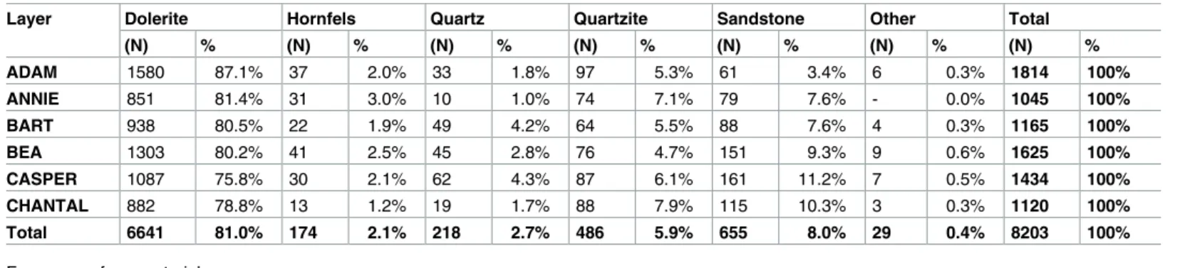
Table 2. Sibudu Cave, basal layers under study.
Layer Dolerite Hornfels Quartz Quartzite Sandstone Other Total
(N) % (N) % (N) % (N) % (N) % (N) % (N) % ADAM 1580 87.1% 37 2.0% 33 1.8% 97 5.3% 61 3.4% 6 0.3% 1814 100% ANNIE 851 81.4% 31 3.0% 10 1.0% 74 7.1% 79 7.6% - 0.0% 1045 100% BART 938 80.5% 22 1.9% 49 4.2% 64 5.5% 88 7.6% 4 0.3% 1165 100% BEA 1303 80.2% 41 2.5% 45 2.8% 76 4.7% 151 9.3% 9 0.6% 1625 100% CASPER 1087 75.8% 30 2.1% 62 4.3% 87 6.1% 161 11.2% 7 0.5% 1434 100% CHANTAL 882 78.8% 13 1.2% 19 1.7% 88 7.9% 115 10.3% 3 0.3% 1120 100% Total 6641 81.0% 174 2.1% 218 2.7% 486 5.9% 655 8.0% 29 0.4% 8203 100%
Frequency of raw materials.
Material under study and research questions
The serrated pieces come from the layers Bart, Bea, Casper, Chantal and Darya. We identified
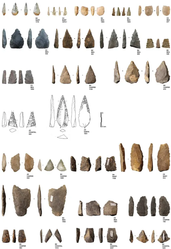
a total of 25 serrated pieces (Fig 4) (All tools are under storage at the museum of
Pietermaritz-burg). For the present study, we assess the technological and functional variability of this assemblage.
Fig 3. Sibudu basal deposits—Assemblage composition. Blades (1–3); Laminar cores (4–6).
https://doi.org/10.1371/journal.pone.0175151.g003
Table 3. Sibudu Cave, all basal layers.
Layer Blanks Tools Cores Hammerstones Debris Total
(N) % (N) % (N) % (N) % (N) % (N) % ADAM 1630 89.9% 124 6.8% 22 1.2% 10 0.6% 28 1.5% 1814 100% ANNIE 947 90.6% 68 6.5% 15 1.4% 5 0.5% 10 1.0% 1045 100% BART 1050 90.1% 80 6.9% 16 1.4% 8 0.7% 11 0.9% 1165 100% BEA 1463 90.0% 146 9.0% 6 0.4% - 0.0% 10 0.6% 1625 100% CASPER 1302 90.8% 111 7.7% 6 0.4% 1 0.1% 14 1.0% 1434 100% CHANTAL 1015 90.6% 86 7.7% 6 0.5% 4 0.4% 9 0.8% 1120 100% Total 7407 90.3% 615 7.5% 71 0.9% 28 0.3% 82 1.0% 8203 100%
General technological classification of lithic artefacts. https://doi.org/10.1371/journal.pone.0175151.t003
The pieces have a mean length of 41 mm, a mean width of 23 mm and a mean thickness of
8 mm (Fig 5;Table 6). Their length-width-ratio is 1.73 +/-0.5 and their width-thickness-ratio
is of 2.9 +/-0.8. The population under study has a bilateral symmetry and a general triangular morphology. The profile of the tools is straight but the delineation of their edges is variable, often sinuous in the proximal part and more regular in the distal part. This regularity partly relates to the alternation of the notches when they are bifacial, either the notches are bifacially symmetric (the bifacial notches originate in a same contact point) or asymmetric (the bifacial notches originate next to each other’s contact point). We found some variability on the cross-sections which range from being bevelled, biconvex or plano-convex, suggesting a degree of variability in the bifacial reduction sequences.
The population of serrated pieces shows some variability that interestingly, relates to the nature of the rocks that have been shaped. In this regard, pieces made from quartz can be dis-tinguished from those made from quartzite, hornfels and dolerite. Firstly, there are differences in tool size, with quartz pieces being smaller than those manufactured from other raw
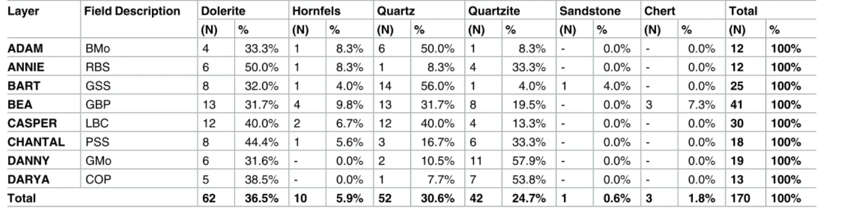
Table 4. Sibudu, basal layers under study.
Layer Field Description Dolerite Hornfels Quartz Quartzite Sandstone Chert Total
(N) % (N) % (N) % (N) % (N) % (N) % (N) % ADAM BMo 4 33.3% 1 8.3% 6 50.0% 1 8.3% - 0.0% - 0.0% 12 100% ANNIE RBS 6 50.0% 1 8.3% 1 8.3% 4 33.3% - 0.0% - 0.0% 12 100% BART GSS 8 32.0% 1 4.0% 14 56.0% 1 4.0% 1 4.0% - 0.0% 25 100% BEA GBP 13 31.7% 4 9.8% 13 31.7% 8 19.5% - 0.0% 3 7.3% 41 100% CASPER LBC 12 40.0% 2 6.7% 12 40.0% 4 13.3% - 0.0% - 0.0% 30 100% CHANTAL PSS 8 44.4% 1 5.6% 3 16.7% 6 33.3% - 0.0% - 0.0% 18 100% DANNY GMo 6 31.6% - 0.0% 2 10.5% 11 57.9% - 0.0% - 0.0% 19 100% DARYA COP 5 38.5% - 0.0% 1 7.7% 7 53.8% - 0.0% - 0.0% 13 100% Total 62 36.5% 10 5.9% 52 30.6% 42 24.7% 1 0.6% 3 1.8% 170 100%
Frequency of raw material types in bifacial pieces. https://doi.org/10.1371/journal.pone.0175151.t004
Table 5. Sibudu, basal layers under study.
Layer Bifacial Tool* Pointed
Form** Scraper-like Form*** Denticulate Indet. Fragment Total (N) % (N) % (N) % (N) % (N) % (N) % ADAM 12 9.7% 66 53.2% 19 15.3% 8 6.5% 19 15.3% 124 100% ANNIE 12 17.6% 31 45.6% 14 20.6% 4 5.9% 7 10.3% 68 100% BART 25 31.3% 32 40.0% 8 10.0% 4 5.0% 11 13.8% 80 100% BEA 41 28.1% 62 42.5% 18 12.3% 7 4.8% 18 12.3% 146 100% CASPER 30 27.0% 50 45.0% 13 11.7% 10 9.0% 8 7.2% 111 100% CHANTAL 18 20.9% 39 45.3% 17 19.8% 2 2.3% 10 11.6% 86 100% DANNY 19 17.6% 46 42.6% 31 28.7% 1 0.9% 11 10.2% 108 100% DARYA 13 17.8% 25 34.2% 20 27.4% 1 1.4% 14 19.2% 73 100% Total 170 21.4% 351 44.1% 140 17.6% 37 4.6% 98 12.3% 796 100%
Frequency of tool types:
*Including all serrated pieces;
**Including ACTs and Tongatis;
***Including NBTs).
Fig 4. Sibudu basal deposits—Overview of all serrated pieces. Analysed serrated pieces (rows 1–4);
Unused and unanalysed serrated pieces (rows 5–7). https://doi.org/10.1371/journal.pone.0175151.g004
materials (Figs4and5). In addition, there is some variation in the morphologies of the bifacial pieces: when bases are preserved, they are semi-circular in the case of quartz and straight for the other raw materials.
To interpret size and shape differences, we first have to acknowledge the technological
vari-ability within this population or, in other words, theirchaînes opératoires. Although our
sam-ple is small, limited to 25 pieces, and we presently lack a global understanding of the associated lithic assemblages, we can nevertheless present some preliminary observations based on our examination. First of all, the sample can be subdivided into two groups: bifacially shaped blanks that were bilaterally serrated (n = 11) and bifacially (or unifacially) retouched blanks that were laterally or bilaterally serrated (n = 14). While we recognize two techno-typological groups, we cannot discern clear differences between them in terms of their morphology or dimension. In general, we suggest that these two reduction sequences reflect different ways to obtain a similar result, namely a triangular elongated tool with serrated edges. However, we again observe a difference between the quartz pieces and those made from other rock types, as the quartz pieces always correspond to the category of bifacially shaped blanks that have been bifacially serrated. We will further elaborate on how we interpret differences between the raw materials that were used by inhabitants of Sibudu, in the discussion.
For a better understanding of thechaînes opératoires, we integrate some preliminary
obser-vations based on the bifacial pieces (not serrated) derived from the same layers as the serrated pieces. We will refer to these non-serrated pieces as the ‘formal bifacial pieces’. Of the total number of 168 bifacials, 143 are formal bifacial pieces, and the rest are serrated. This means that approximately one out of every six bifacial pieces was serrated.
Thechaîne opératoire as deduced from the full assemblage of bifacial pieces begins with the
knapping of elongated products. These blanks indicate that there would not have been a great Fig 5. Sibudu basal deposits. A—scatter plot of widths and lengths of all complete serrated pieces (red
cross–quartz, blue squares–dolerite and hornfels); B—Box plot of maximal width of all serrated pieces in comparison to the used points exclusively; C—Box plot of maximal thickness of all serrated pieces in comparison to the used points exclusively.
degree of pre-determination and from the presence of cortex often seem to originate from an initial phase of the core reduction. Currently, there appears to be no specific core reduction sequence that was oriented toward the production of blanks to be selected for bifacial shaping. Once the toolmakers selected the appropriate piece, they shaped it by direct percussion until they achieved the desired dimension and shape in terms of bilateral and bifacial symmetries. The set-up of the desired forms was therefore related to the different parameters of the percus-sive technique, i.e. the force that was applied, the motion of the percussion (more or less tan-gential) and the location of the impact point (more or less at the interior of the edge). It is only after this shaping procedure that a series of notches was set up, intended to serrate the edges.
Interestingly, no firm signs of reworking were recognised on the serrated pieces, suggesting that the serration was not only the last stage of the manufacturing process, but also its final stage. It suggests to us the existence of a techno-economical distinction between the serrated bifacial pieces that represent finished tools (in terms of morphometric characteristics) and the formal bifacial pieces that seem to have been shaped at different times throughout their life cycles. We can draw two primary conclusions from this observation. First, the serrated pieces under study can all be regarded as finished forms, with the exception of the pieces that frac-tured during the manufacturing process. Second, the variability of raw materials, dimensions and shapes is not related to differences in their stages of discard.
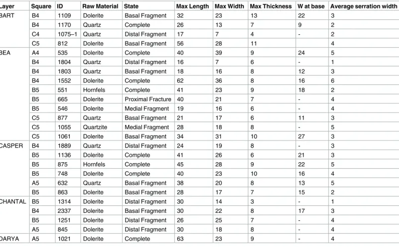
Table 6. Sibudu, basal layers under study.
Layer Square ID Raw Material State Max Length Max Width Max Thickness W at base Average serration width
BART B4 1109 Dolerite Basal Fragment 32 23 13 22 3
B4 1170 Quartz Complete 26 13 7 9 2
C4 1075–1 Quartz Distal Fragment 17 7 4 - 2
C5 812 Dolerite Basal Fragment 56 28 11 4
BEA A4 535 Dolerite Complete 40 39 9 24 5
B4 1804 Quartz Distal Fragment 16 7 6 - 1
B4 1803 Quartz Basal Fragment 18 16 8 12 3
B4 1552 Dolerite Complete 62 36 8 16 6
B5 551 Hornfels Complete 41 23 9 18 2
B5 665 Dolerite Proximal Fracture 40 21 7 - 4
B5 546 Dolerite Medial Fragment 19 16 6 - 4
C5 877 Quartz Basal Fragment 21 17 6 11 3
C5 1055 Quartzite Medial Fragment 28 18 8 - 5
C5 1061 Dolerite Basal Fragment 34 31 10 27 3
CASPER B4 1889 Quartz Distal Fragment 24 19 8 - 3
B5 1136 Dolerite Complete 41 26 6 21 3
B5 875 Hornfels Complete 45 28 9 22 5
B5 748 Dolerite Complete 40 23 10 16 4
A5 632 Quartz Basal Fragment 38 20 8 13 5
B5 863 Dolerite Basal Fragment 28 17 7 15 2
CHANTAL B5 1314 Dolerite Distal Fragment 30 14 3 - 1
B4 2337 Dolerite Basal Fragment 30 22 8 17 3
B5 1251 Dolerite Distal Fragment 26 25 7 - 4
A5 845 Dolerite Distal Fragment 30 18 8 - 4
DARYA A5 1021 Dolerite Complete 63 23 9 - 4
Description of serrated pieces (including specimen numbers). https://doi.org/10.1371/journal.pone.0175151.t006
We note a certain amount of variation between the serrated points according to the notches. First of all, we have to acknowledge that the serration is not equally explicit on all the pieces. Some tools are regularly serrated all along their edges while others show more discontinuous serrations. Some tools have deep notches while on others they are very shallow. Also, some tools are bifacially notched while others are only unifacially serrated. The serration never occurs at the base of the points—notches are always visible on the medial part and, to a lesser extent, on the distal part. We consider that this variability is related to the function of the pieces or to the tool that was used to serrate the blank. To help determine the causes of variability we took measurements of all notches (n = 288, mean of 11 to 12 notches measured per serrated piece), using Photoshop software. The notches have a mean width of 3.2 mm, with a standard deviation of 1.7 mm, and a mean depth of 0.5 mm, with a standard deviation of 0.3 mm.
Apart from the raw material, functional factors may explain the variation we observe among the serrated pieces. For the functional analysis, 18 bifacially serrated points or point fragments were considered, as the rest of seven pieces appear not to have been completed, and thus, were never used. The pieces come from the layers Bart, Bea, Casper and Chantal, and also include one serrated piece from the lowermost layer Darya. From the total sample of 18 bifacial serrated points and point fragments, one serrated point with a broken tip (B5-863) had to be excluded due to significant iron deposits and cracking, which prevented a reliable func-tional analysis. An independent use-wear and residue analysis were performed on the
remain-ing 17 artefacts (Table 7). Different microscopic techniques were combined and the analysis
was performed in specific stages: (1) a broad screening performed by Veerle Rots to under-stand general wear patterns and to allow an informed selection of tools that would be relevant for residue analysis, (2) residue analysis of the stone tools performed by Carol Lentfer, (3) use-wear analysis of the stone tools performed by Veerle Rots.
The serrated pieces from Sibudu represent one peculiar innovation that has presently received little attention. While serration has long been associated with the pressure technique (Crabtree 1973), the question of the technique used to notch the edges of the bifacial blanks still needs to be firmly demonstrated. Similarly, the functional reason for serrated edges still remains to be clarified. It was with two questions in mind—1) how was the serration applied?, 2) what was the serration for?–that we established our methodology.
Methods of the functional analysis
Tools were first screened under a binocular stereoscopic microscope (magnifications up to x56). Potential evidence of use and hafting was documented and a working hypothesis was proposed. Based on this broad examination, relevant tools were selected for detailed functional
analysis including residues and use-wear (Table 7). While a general priority listing of the tools
was made, no details of the screening were communicated to the residue analyst.
Most tools prior to screening were unwashed and unhandled. However, all had been han-dled for photography prior to the detailed functional analysis. Such handling resulted in con-tamination residues, consisting of skin flakes from dust and handling, fibres including easily recognised synthetic fibres, plasticine that was used for mounting some specimens while
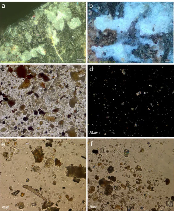
pho-tographing them, and possibly some of the starch granules (Fig 6a and 6b). To avoid further
chances of contamination starch-free gloves were worn during the screening process and sub-sequent residue analyses.
Residue analysis of tools
Fifteen tools, including broken fragments, with diagnostic production and/or use-related attri-butes were selected for residue analysis. The analysis was based primarily on morphological
identification of microscopic residues using stereo binocular, metallurgical, transmitted and occasionally scanning electron microscopy.
The initial stages of the analysis followed standard micro-residue analytical procedures
(e.g., [37,38]) using an Olympus SZX7 binocular stereomicroscope and a Zeiss AxioZoom V16
zoom microscope to scan all surfaces of tools and record the distribution of discernible resi-dues and sediment onto line drawings. Magnification ranges at this stage were from x5.6 to x180 and images were taken with the Zeiss V16 zoom microscope of selected residues. Follow-ing this initial procedure, tools were systematically examined at higher magnifications rangFollow-ing from x50 to x1000 using Zeiss and Olympus metallurgical microscopes fitted with dark field and bright field incident light sources, polarising filters, differential interference contrast (DIC) and cameras. Locations of micro-residues were recorded onto line drawings and repre-sentative residues were photographed.
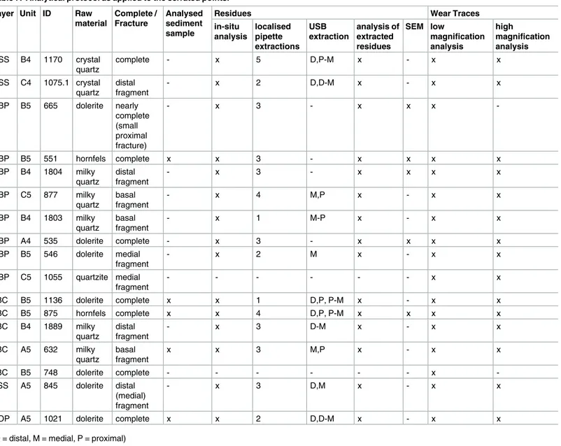
Table 7. Analytical protocol as applied to the serrated points.
Layer Unit ID Raw
material Complete / Fracture Analysed sediment sample
Residues Wear Traces
in-situ analysis localised pipette extractions USB extraction analysis of extracted residues SEM low magnification analysis high magnification analysis GSS B4 1170 crystal quartz complete - x 5 D,P-M x - x x GSS C4 1075.1 crystal quartz distal fragment - x 2 D,D-M x - x x GBP B5 665 dolerite nearly complete (small proximal fracture) - x 3 - x x x -GBP B5 551 hornfels complete x x 3 - x x x x GBP B4 1804 milky quartz distal fragment - x 3 - x x x x GBP C5 877 milky quartz basal fragment - x 4 M,P x - x x GBP B4 1803 milky quartz basal fragment - x 1 M-P x - x x GBP A4 535 dolerite complete - x 3 - x x x x GBP B5 546 dolerite medial fragment - x 2 M x - x x GBP C5 1055 quartzite medial fragment - - - x x LBC B5 1136 dolerite complete x x 1 D,P, P-M x - x x LBC B5 875 hornfels complete x x 4 D,P, P-M x x x x LBC B4 1889 milky quartz distal fragment - x 3 D-M x - x x LBC A5 632 milky quartz basal fragment x x 3 M,P x - x x LBC B5 748 dolerite complete - - - x -PSS A5 845 dolerite distal (medial) fragment - x 3 D,M x - x x
COP A5 1021 dolerite complete x x 2 D,D-M x - x x
(D = distal, M = medial, P = proximal) https://doi.org/10.1371/journal.pone.0175151.t007
In a subsequent stage, following procedures adopted by Loy [39] and others (e.g., [40]), transmitted light microscopy was employed to confirm presence and identification of residues observed with reflected light. This procedure also enables detection of other diagnostic resi-dues such as small fibres, starch, phytoliths, other plant and animal tissue fragments, crystals and minerals that may not, or could not have been detected with reflected light. For each tool, Fig 6. Examples of contamination and residues from associated sediment. a) abundant skin tissue from
post excavation handling on the ventral left proximal edge of 665 (x500, bright field); b) plasticine contamination on the dorsal left proximal end of 1170 (x500, dark field); c) elongate phytoliths, articulated plant tissue cf. Commelinidae, charred palynofacies and other sedimentary particles in sediment sample from layer Bea (x400, transmitted light); d) pleochroic particles of CaCO3 from sediment sample from layer Casper (x400, transmitted polarised light); e) spores, sclereid and lobed CaCO3 crystal from hyrax faecal sample (the crystal is typically found in urine) (x400, transmitted light); f) other pleochroic crystals, spores and fibre from hyrax faecal sample (x400, transmitted light).
various locations noted to have residues and/or locations that would be expected to have diag-nostic residues if the tool had been used were selected for sampling. A small amount of distilled
water (a minimum of 200μl) was pipetted onto each of these locations and the wetted sample
residue was redrawn into the pipette then transferred to a microscope slide. Dependent upon the adherence of residues, additional application of water and/or abrasion with the pipette tip to help remove particles was sometimes utilised. Slide samples were mounted in distilled water and examined under x100 to x400 magnification using a Zeiss Axioscope.A1 microscope with normal and polarised light as well as DIC. Presence of individual types of residue was recorded and relative abundance of significant residues was noted. Images were taken with a Zeiss Axio-Cam ICc5 microscope dedicated camera.
To further assess residue presence and abundance, tools were placed into an ultra-sonic bath (USB) with distilled water to remove samples of remaining residues from tool surfaces. To help remove contaminants such as fibres and skin cells derived from handling and expo-sure to air-borne dust, tools were lightly washed in distilled water prior to USB. Treatment was five minutes per bath. Distal and proximal portions of unbroken tools were treated separately. Likewise, for broken pieces, distal or proximal and medial sections of tools were treated sepa-rately. For whole tools medial sections were sampled by immersing the already treated proxi-mal ends together with un-treated medial sections into water. Residues removed in this way were analysed in accordance with the pipette samples. In instances where very large amounts of residue were obtained via the USB, sub-samples were scanned until the number of new types encountered in samples plateaued. It should be noted that four tools with sufficient resi-dues for gas chromatography-mass spectrometry (GC-MS and/or GC-GC) analysis and the proximal to medial portion of another tool were not given the USB treatment. The inclusion of the USB procedure has the advantage that samples of all relevant residues were extracted and no further precautions were necessary during subsequent handling and analysis.
Selected residues on five tools (four selected for GC-MS) were examined and characterised with the environmental SEM facility (FEI XL30 ESEM-FEG) available at the University of Liège. Micrographs were obtained for respective residues and elemental energy dispersive X-ray (EDX) analysis was undertaken. No coatings were applied during this procedure.
The sedimentary context: Implications for preservation of residues and
background ‘noise’
To facilitate our interpretations of production/use-related residues vs environmental/post-depositional residues, analysis of 7 sub-samples of sedimentary layers associated with the stone
tools was undertaken (Table 8). To ensure homogeneity of the sediment samples, collection
bags containing samples were well-shaken prior to treatment. One cm3of each sample was
placed into a 6 ml vial with distilled water and disaggregated by vigorous shaking for 2 min-utes, then USB treatment for five minutes. Sub-samples of the disaggregated samples were transferred to microscope slides and analysed in accordance with the procedures used for the pipette and USB samples of tool residues.
Starch, animal tissue traces and vivianite, a hydrated iron phosphate mineral often found in association with animal residues, were extremely rare in the sediment samples. Therefore, their presence on tool surfaces can be due to more favourable micro-environmental conditions enabling their preservation or to being used in tool manufacture and/or related to tool func-tion. The preservation of a range of other organic residues in the sediment samples was
excel-lent (Table 8) and provides a background by which to assess ‘noise’ residue, unrelated to tool
production and function. Charred plant fragments and phytoliths indicated an abundance of
Table 8. Summary of residues found in sediment samples . Code (associat ed tool) Animal Plant Mineral Other Comm ents Tissue Bone Tissue Fibre Phytolith Vivianite Hematite Crystal Sedime ntary particle s (indet.) Micro-char coal/ TA palynofaci es Tissue (indet.) GSS (650) ab ab ab ab + Commelin idae tissue and phytolith s abundant —diagnostic sedge tissue present. Charred particles abundan t. LBC (2195) c c ab ab + Commelin idae tissue and phytolith s present. Diagnost ic morpho types absent. LBC (632) vc c ? ab vc + Commelin idae tissue and phytolith s present. Nodular globula r phytolith s cf. Dilleniidae present. Aggregate s of pleochroic CaCO3 particles very common. LBC (1136) vc c CaCO3 ab ab + Commelin idae tissue and phytolith s present. Nodular globula r phytolith s cf. Dilleniidae present. GBP (551) ab + ab ab ab + Commelin idae tissue and phytolith s present including grass trichomes . Nodular globular phytoliths cf. Dilleniidae present. GBP (1006) ? ab + ab + CaCO3 ab ab + Commelin idae tissue and phytolith s from grass and sedge present. Nodular globular phytoliths cf. Dilleniidae present. COP (1021) + ab + ab an ab + Commelin idae tissue and phytolith s mostly from grass. + (presen t), c (common ), vc (very common) , ab (abundant ).? means uncertain identification . https://do i.org/10.1371/j ournal.pone .0175151.t008
includingDilleniidae species (e.g., Moraceae and Euphorbiaceae spp.) (Table 8;Fig 6c and 6d). Diagnostic epidermal long cell and short cell phytoliths from panicoid grasses were
occasion-ally present, but absent and/or rare in most sediment samples. Hence, it is likely that the
Com-melinidae micro-fossils were primarily derived from sedges. This is in accordance with
previous studies of the higher stratigraphic levels that identified an abundance of burnt plant material, particularly sedge, interpreted as being from bedding material that was burnt
fre-quently for site maintenance [41], and ultimately contributed to the creation of the distinct
laminated strata of the MSA sedimentary sequence of Sibudu Cave, or so it is thought
[19,22,42].
Plant remains would have been brought into the rock shelter by other means too, not only humans, and the taphonomic implications of this, especially with regard to preservation of res-idues and background ‘noise’ should be considered. At Sibudu, an obvious source would be
the rock hyrax (Procavia capensis); currently a common inhabitant of the rock shelter and
highly likely to have lived there during the MSA. This small-sized mammal browses upon a broad spectrum of plants, including sedges and grasses, as well as twigs, shoots, leaves and
flowers from shrubs and small trees, lichens and liverworts [43]. Although they generally eat
on the spot (i.e., close to the food source), and are not known for carrying food back to shelters
for eating, they do have a peculiar habit of defecating under shelter [44]. By so-doing, they
cre-ate large, often well-stratified urino-faecal middens, packed full of plant remains and very
use-ful for paleoenvironmental analysis [43–45]. Currently, one such midden is on an elevated
platform in the south-western section of the Sibudu rock shelter and an analysis of the masti-cated components of a sample of faecal pellets from here, did indeed confirm the varied diet of rock hyrax, at least in the present day environment around Sibudu. The sample analysed con-sisted of large stellate trichomes, other trichomes, large sheets of epidermis, sclereids and woody tissue fragments from dicotyledinous plants, as well as grass and sedge epidermis and phytoliths, pollen, lichen and fungal spores. There were also remains of invertebrate append-ages, exoskeletons, including fragments of millipede exoskeleton, and scales from the wings of butterflies or moths, which may or may not have been intentionally consumed. Therefore, given the likelihood of the rock hyrax being an inhabitant of the rock shelter in the MSA, it would undoubtedly have made substantial contributions to the plant material found in sedi-mentary deposits. Moreover, and perhaps most importantly for sedisedi-mentary formation pro-cesses, the rock hyrax has a unique physiology giving it the ability to concentrate its urine to
reduce water loss, and allowing it to successfully live in arid environments [46]. The dried,
car-bonate-rich urine (hyraceum) from hyrax, is also likely to be a major source of the calcium
oxalate crystals, granular casts and pleochroic calcium carbonate crystals (Fig 6e and 6f), very
common components of the sediment samples. Furthermore, since it caps faecal deposits much like the calcitic concretions that caps sedimentary deposits in limestone caves, its disso-lution and re-precipitation within the rock shelter deposits may have been instrumental to the formation of their finely laminated strata and the outstanding preservation of organic
material.
Wear analysis
For the wear analysis, all 17 tools were examined under a binocular stereoscopic microscope (magnifications up to x56; Zeiss and Olympus), a zoom microscope (Zeiss V16, magnification up to x180), and a metallurgical reflected-light microscope equipped with bright field illumina-tion, polarising filters and DIC (magnifications up to x1000) (Olympus BX51M) according to
established procedures (cf. highlighted in [47]). Pictures were taken with adapted microscope
polish, striations and rounding. Given that all residue extractions were performed before the detailed use-wear analysis started, tools could be handled and cleaned with alcohol or acetone during analysis without the risk of contaminating or removing residues. This cleaning proce-dure is essential in order to be able to correctly observe polish and striations. Special attention was also devoted to fractures and fracture patterns. Projectiles were interpreted on a combina-tion of different wear traces in specific patterns and no interpretacombina-tion relied on one wear type
only (cf. [14]). For describing fractures, terminological ambiguities were avoided as much as
possible (cf. [48]).
Reference material
Interpretation of residues and wear traces were based on the experimental reference collection available at TraceoLab, University of Liège. This collection consists of modern comparative reference materials and over 3000 experimental tools produced in various ways and used in
various activities both in the hand and hafted in various arrangements (e.g., [47]). The
collec-tion consists primarily of flint tools, but also tools made from chert, quartz, quartz crystal, obsidian, and dolerite. About 300 experimental flakes (used and unused) are currently avail-able in raw materials that were used at Sibudu, especially dolerite. A specific experimental pro-gram on serrated pieces was initiated within the framework of this study (see below).
Additionally, published and unpublished comparative reference databases were used for the residue analysis, including comprehensive starch plant fibre and phytolith modern
compara-tive reference collections compiled by Lentfer (e.g., [49–51]). Also, with regard to iron oxide
residue it should be noted that extreme care was taken for the identification of applied
hema-tite on stone tool surfaces. Iron oxide occurs in dolerite and hornfels rock types (see [33]:
Table 4a: 103) being often visible in the rock matrix in the form of olivine which weathers to
goethite (hydrated iron oxide) and hematite (iron oxide). The latter is indicated by a distinct red colouration on weathered rock surfaces. Knapping experiments with dolerite found near the Sibudu rock shelter confirmed that the rock often broke along weathered fracture lines to reveal hematite on freshly broken surfaces. Hence, its classification as applied residue was dependent on its thickness and distribution and/or its association with other residues such as resin, fat, micro-charcoal, starch and other plant material or tissue used for compound adhe-sives or other hafting elements.
Experimentation
A reference sample of serrated points was reproduced experimentally. Fourty-three serrated points were manufactured by a knapper with 20 years of experience, Christian Lepers (Univer-sity of Liège): 21 out of quartz crystal, 8 out of quartz, 10 out of dolerite, and 4 out of flint. All blanks were shaped with a wooden hammer and serrated by pressure with a bone compressor. The goal of the knapper was to shape a pointed form with a maximal width located in the 1/3 proximal part, a bilateral symmetry and a point angle comprised between 45˚ and 55˚. No spe-cial indications were given regarding the characteristics of the sections, nor of the bases. Once the blank was bifacially shaped, the instruction was to serrate the edges bifacially without any specification regarding the alternation of the notches.
Some points were not entirely finished due to them fracturing early in the production sequence (7 in crystal quartz, 4 in quartz, 3 in dolerite), or in a later production stage when they were close to being finished (2 in crystal quartz, 1 in dolerite). Three serrated points in crystal quartz were completed, but ended up very small owing to the correction of some frac-tures during the production process. All the points or preforms that fractured during produc-tion served as a comparative reference for the analysis of the archaeological points.
Additionally, all the small shaping flakes were collected and in instances where no early frac-tures occurred, flakes were separated for each shaping phase (e.g., initial shaping, advanced shaping, finishing). These shaping flakes were examined, in particular their butt, to record the wear that results from the pressure flaking process.
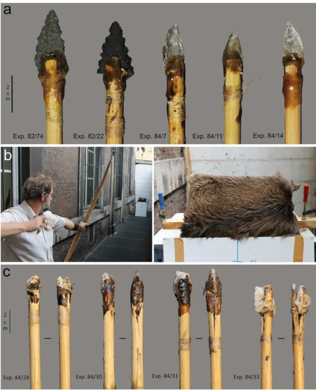
Twenty-three serrated points (9 in quartz crystal, 4 in quartz, 4 in flint, 6 in dolerite) were mounted in a split on the extremity of pine shafts (11/32 inch in diameter; average spin of 1.21 cm) with the aid of resin (70% natural pine resin, 30% beeswax) or resin combined with sinew
bindings (Fig 7;Table 9). Points were shot into an artificial target with a 47 pound (draw
weight) flat bow manufactured out of elm (30 inch draw distance) (Fig 7). Shots were taken at
a distance of 10 m from the target. The target consisted of ribs incorporated in a ballistic gel
(240–260 bloom; gelatine type A; 24h in cold chamber at 4˚C; cf. [52]) and was covered with a
remoistened animal hide (horse) fixed tightly around the gel. A double series of ribs was used to increase the chance of impact damage by contact against bone. The goal was not to produce an experimental set that would be representative in terms of fracture frequencies, but to sup-plement the existing projectile reference collection of the TraceoLab (nearly 500 points) with fracture points on samples of raw material and point morphology highly similar to the archae-ological points. Points were shot once unless no damage occurred at all, in which case they were re-used. No point was shot more than four times and the total number of shots was 33
(Table 9). Two out of 23 points missed the target and hit a soft stone wall (itong), while 4
points successfully hit the target, but bounced off and hit the soft stone wall.
Fractures occurred as a result of the contact with the hide as well as the contact with bone.
Given the robustness of the target, de-hafting occurred frequently (Fig 7). In general, the
projec-tiles in quartz proved very resistant to damage when used as a projectile. The damage that was
incurred consisted of small fractures or unifacial scars and crushing (Fig 8). The projectiles in
dolerite showed clear signs of damage, including a lot of abrasion of the edges. The edge-wear susceptibility of the edges was of course reduced by the bifacial nature of the pieces. It has been
observed experimentally (cf. [53]; TraceoLab experiments) that bifacial points are more
resis-tant to damage than unretouched or unifacially retouched points. Also this experiment showed that bifacial points suffered from relatively little damage in spite of the experimental setting that was intended to intensify damage formation by increasing the chances of contact with bone.
Results
Evidence of tool production, use and hafting was observed in the form of residues and wear traces. In spite of the age of the material, residues were very well-preserved, which concurs
with previous studies at Sibudu [54–56] and corresponds to the general pattern of high quality
preservation of organic material in South African cave and rock shelter sites. Interpretations are based on a combination of different residue types related to a single type of worked mate-rial (e.g., combination of collagen, animal tissue and tendons in the case of animal-related
use), which significantly strengthens the link of a residue with a tool’s use [57]. Residue
causal-ity is further confirmed through the combination with an independent wear analysis (cf. [58]).
For the present study, the analytical research revolved around three main questions: 1) what is the evidence for the use of pressure flaking to serrate the bifacial pieces? 2) what were the serrated points used for? 3) how were the serrated points used, and in particular, is there evidence of hafting?
Evidence for pressure flaking
To test the hypothesis that the serration was created by pressure, we examined different types of data corresponding to both the effect of the technique used and the direct contact between
Fig 7. Projectile experiments. a) hafted experimental projectiles before the experiment; b) experimental set-up including
target used on the right (The individual in this picture has given his written informed consent); c) hafted experimental
projectiles after the experiment showing fractured projectile tips, cut bindings, as well as points that inserted into the shaft upon impact.
Table 9. Experiment al data for the projectile experimen ts includ ing all ballistic informatio n. Ref Nr Raw material Pine shaft morphology Diameter of shaft Gross mass of shaft (g) Mass of stone point (g) Mass hafted tool (g) Type of fletching surface de frottement empennage Length of shaft (cm) Total L shaft + point (cm) Point of equilibrium of the finished tool (cm from the point tip) FOC of the
finished arrow (FOC
((L/2-Lgrav)/L) *100) Fixation Number of shots Contact material Penetration in target (cm) Result Exp. 82/ 22 dolerite cylindrical 11/32 32.89 2.27 35.45 3 x 5 inch parabolic 82.0 84.0 41.2 0.95 glue 1 skin+gel 0
point breakage; dehafted
Exp. 82/ 74 dolerite 28.38 3.89 32.61 82.0 84.6 37.2 6.03 glue 1 wall 0
point breakage; dehafted
Exp. 82/ 135 dolerite 30.27 6.03 36.91 82.0 83.5 36.9 5.81 glue 2 (1) skin+gel; (2) skin+gel+wood 2.0 de-hafted Exp. 82/ 250 dolerite 36.78 36.78 82.0 85.0 33.5 10.59 glue+sinew +glue 1 skin 0 de-hafted (shaft broke) Exp. 82/ 251 dolerite 37,00 37 82.0 87.0 39.0 5.17 glue+sinew +glue 2 (1) skin+gel; (2) skin+gel+bone (1) 9.5; (2) 5.5 + point
point breakage; dehafted
Exp. 82/ 252 dolerite 29.86 29.86 82.0 83.6 37.0 5.74 glue+sinew +glue 1 skin 0 de-hafted on impact Exp. 84/ 06 quartz crystal 26.78 0.68 27.77 82.0 83.6 41.0 0.96 glue 1 skin+gel 41.0 point breakage in haft Exp. 84/ 07 quartz crystal 28.28 2.3 31.03 82.0 84.2 40.0 2.49 glue 1 skin+gel 19.5 Exp. 84/ 08 quartz crystal 26.29 1.65 28.16 83.5 85.3 39.9 3.22 glue 2 (1) skin+gel +bone; (2) skin +gel (1) 45.5; (2) 21.8 point breakage in haft Exp. 84/ 10 quartz crystal 26.79 3.36 30.58 83.5 85.2 38.5 4.81 glue 1 skin+gel+bone 0 de-hafted Exp. 84/ 11 quartz crystal 28.27 1.01 29.54 83.5 85.5 42.1 0.76 glue 1 skin+wall 0
point breakage; dehafted
Exp. 84/ 14 quartz crystal 28.5 2.26 31 83.5 85.7 40.6 2.63 glue 1 skin+gel+bone +wall 0
point breakage; dehafted
Exp. 84/ 15 flint 33.46 2.91 33.12 83.5 86.5 41.5 2.02 glue 2 (1) skin+ gel; (2) wall 48.0
point breakage; dehafted
Exp. 84/ 24 flint 36.56 35.5 82.0 84.5 35.5 7.99 glue+sinew +glue 1 skin+gel+bone 10.5 point breakage in haft Exp. 84/ 25 flint 34.1 34.1 82.0 86.5 37.0 7.23 glue+sinew +glue 3 (1–2) skin+gel; (3) skin+gel +bone (1) 23.0; (2) 21.0; (3) 13.0 + point
point breakage; dehafted
Exp. 84/ 26 flint 33.59 33.59 82.0 84.0 37.0 5.95 glue+sinew +glue 2 (1) skin+gel; (2) skin+gel+bone (1) 13.5; (2) 9.0 point breakage in haft Exp. 84/ 27 quartz 30.49 30.49 82.0 86.5 40.0 3.76 glue+sinew +glue 1 skin+gel+bone 2
point breakage; dehafted
Exp. 84/ 28 quartz crystal 28.76 28.76 82.0 83.5 39.5 2.69 glue+sinew +glue 1 skin+wall 0 point breakage in haft Exp. 84/ 29 quartz crystal 35.46 35.46 82.0 83,0 40.0 1.81 glue+sinew +glue 1 skin+gel 9.0 + point dehafted Exp. 84/ 30 quartz crystal 28.85 28.85 82.0 85.5 42.0 0.88 glue+sinew +glue 1 skin+gel+bone 10.3 point breakage in haft Exp. 84/ 31 quartz 29.59 29.59 82.0 83.0 38.5 3.61 glue+sinew +glue 4 (1–3) skin+gel; (4) skin+gel +bone (1) 14.0; (2) 16.0; (3) 18.0; (4) 17.0 + distal tip of point point breakage in haft Exp. 84/ 32 quartz 32.52 32.52 82.0 82.0 34.8 7.56 glue+sinew +glue 1 skin 0 dehafted Exp. 84/ 33 quartz 30.45 30.45 82.0 86.0 40.3 3.14 glue+sinew +glue 1 skin+wall 0 point breakage in haft Penetrat ion depths in the target could only be measured for points that remain ed stuck in the target after the shot. When the point detached from the shaft inside the target, only the penetration of the shaft (and the remaini ng part of the point, if relevan t) could be measured. The (fractured off) point length should be added to this value (indica ted in the table as “+ point”). https://do i.org/10.1371/j ournal.pone .0175151.t009
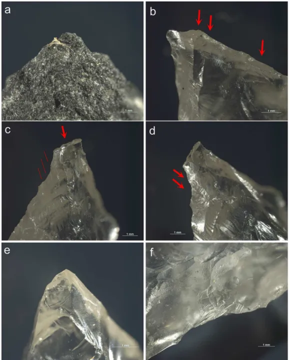
the compressor and the stone tools: 1) evidence on the bifacial pieces (the negative traces), 2) evidence on the shaping flakes (the positive traces), 3) wear and residue evidence from the manufacturing process (the remnant traces). We believe that only the combination of these different lines of evidence allows the demonstration that pressure technique was used or not. Fig 8. Examples of damage caused by impact as recorded on the experimental reference sample. a)
step-terminating bending fracture on the apex of Exp. 82/135 (dolerite; x26.5); b) lateral step-terminating scarring on the ventral apex of Exp. 84/10 (x30.5); c) step-terminating spin-off initiated from the apex fracture on the dorsal distal tip of Exp. 84/10 (x23.5) (also lateral scarring is visible); d) elongated bending initiated and terminating scars on the lateral edge of the dorsal distal tip of Exp. 84/10 (x23.5); e) superposing
step-terminating scars on the ventral distal tip of Exp. 84/7 (x40.5); f) superposing step-step-terminating scars on the right lateral edge of the dorsal distal tip of Exp. 84/7 (x26).
In addition, further support was obtained by examining the bone tool assemblage, by produc-ing a set of experimental replications and by comparproduc-ing with available published data on the
subject of pressure flaking (see [59]).
However, we have to acknowledge the following biases with regard to our study in compari-son to published data:
1. Most of the current literature about pressure flaking deals with raw materials such as flint
and silcrete (e.g., [5]). Differences in rock properties (influencing the way they fracture)
should not be overestimated in the sense that pressure can be applied to all sorts of raw
material [60]. However, the way in which technical scars are recorded can vary significantly
between raw materials and rock properties may blend the usual technical criteria used to establish the diagnosis. In sum, potential differences have to be expected with regard to the nature of the rocks that were shaped. In this regard, the experiments with quartz and doler-ite helped us to re-assess and “calibrate” our list of crdoler-iteria.
2. Secondly, most of the literature deals with pressure flaking and not formally with pressure notching. Pressure flaking aims at regularizing an edge and thinning the sections of the tool, while pressure notching aims at serrating an edge. Both procedures share very similar char-acteristics but there are also variations. In the case of pressure thinning, the compressor has to be placed on the very edge of the blank that would have been initially prepared by abrasion in order to strengthen the contact. The force applied has to be in an angle that is more or less parallel to the plane of the blank. As a consequence, the flake will often have a small bulb and will have an elongated and regular morphology with parallel edges. By contrast, in the case of pressure notching, the compressor has to be placed slightly inside the edge and the applied
force has to be at an angle more or less perpendicular to the plane of the blank [35,61]. This
angle will influence the depth of the notch and consecutively determine the morphologies of the serration flakes (thickness and breadth of the butt and overall morphology).
We also have to acknowledge that discrimination of the use of pressure may be difficult due
to similarities with soft hammer percussion (cf. [5]). However, given the difference in the type
of contact (percussion or pressure), both techniques display different stigmata from the prepa-ration. The use of soft hammer percussion is associated with a tangential percussion which requires an abrasion that is in theory wider and more intense than for pressure, as the exact location of the contact point is more uncertain and the initiating force is more dramatic. This contrasts with a localized and more regular progression in initiating the force with pressure technique. Furthermore, the resulting waste flakes between percussion and pressure vary accordingly, showing differences in the butt morphology, the presence/absence of a lip and a contact point, the characteristic of the bulbs (not extensive but pronounced for pressure versus
no bulb for soft tangential percussion) and hackles on the bulb (but see [62]).
The serrated pieces. Several lines of evidence support the use of pressure. Firstly, as based on previous studies of bifacial pieces, the size of the notches (width and depth) and their
spac-ing is an important parameter [16,36,63]. The regularity of notches (within a single piece)
indi-cates a clear control of the locations of the contact points as well as of the force that was
applied (Fig 9). As noted previously, the assemblage of Sibudu has notches with a mean width
of 3.2± 1.7 mm and a mean depth of 0.5 ± 0.3 mm. These measurements indicate that the tool
used to initiate the removal of the notches should have been of a relatively small size. The key relevant information, however, is the variability in the dimension of the notches. Interestingly, the standard deviation is lower when we consider measurements for individual pieces and sample sets. Indeed, 21 on a total of 25 pieces have notch width measurements with a standard deviation less than 1.7 mm, including 11 pieces with a standard deviation less than 1.1 mm.
Similarly, 17 from a total of 25 pieces have notch depth measurements with a standard devia-tion below 0.3 mm. Both observadevia-tions suggest that the serradevia-tion was more regular per piece than between pieces, which indicates a strong internal homogeneity and control of the notches per piece.
A second argument for the use of the pressure technique comes from the bifacial serration itself. Indeed, creating a notch by percussion requires the edge of the blank to be convex (or rectilinear) in order to ensure a good contact with the hammer. One advantage of the pressure technique is to be able to detach removals in areas that cannot be reached by percussion, such
as concave edges. On a few bifacially serrated pieces (Fig 9), we see that the serration is
sym-metrical on both faces, meaning that the fracture of the last notch was initiated within the con-cavity of the previous one.
Additional evidence relates to the negatives of the serrating removals themselves. These show small hackles and negative bulbs, which are indicative of a narrow contact point.
Fur-thermore, they exhibit parallel edges and a feathered termination [5,7].
Further support comes from the presence of minor abrasions on the edges of the points, on both finished and unfinished forms. Such minor abrasion is applied before pressure flaking to create an artificial placement of the compressor tip behind the edge. Similar abrasion occurred on some experimental points.
Finally, bone residues occurred in association with the negatives of the serration on 11 of
the 15 examined points, in particular on their distal and medial sections (Table 10). Good
examples were observed independent of raw material (e.g., distal edges of 551-hornfels and
1021-dolerite, medial edges of 1803-quartz and 875-hornfels) (Fig 10).
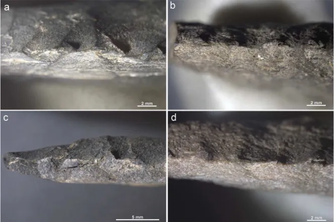
Fig 9. Details of the serration. a) point 535 (x12.4); b) point 546 (x12.4); c) point 1021 (x11.2); d) 1055 (x12.4)
Table 10. Summary of residues on the serrated pieces. Tool number Section Face Animal Plant Mineral Sedimentary particles (indet .) Micro-charcoal/ TA palynofacies Tissue (indet .) Stain Tissue Fibre Sinew/ Connective tissue Skin (ctm .) Hair Proteinaceous residue Blood Fat/ Lipid Bone Tissue Fibre Resin Starch Phytolith Vivianite Hematite Crystal Mg/ Mn 1170 Distal D R T U U RU R?U R R R RU U R?U RU U RU V U U U R?U R R U U U RU RU U U Medial D RT R R? R RT T T T U? U T R RU U RTU V R U? U U RTU Proximal D RTU R R R R R RTU RT R?T? U TU TU T R RU RTU V U U R RTU R RT?U TU U R? RU U RTU 1075.1 Distal D RTU T U? RU U R?T? T T RT? T U T R? R RTU U R V U U? U T R? U R? RTU U Medial D TU T TU? U T R R?T TU R T U R?T? U? RT U U? R?T? R RU RTU U V U U? R? U U R?U? U U? R? R RU RTU U Proximal -535 Distal D RT R R? R R R R R? RT V R R R R R? RT Medial D R R R? RT ? (lin) RT R V RT R? R T RT R T RT R T T RT RT R Proximal D R R V RT R * RT R * RT R 1803 Distal -Medial D RU RU R R U R? RU U RU R? RU RU RTU V RTU T? U R? R? T R TU T R U TU RU U RTU RU RTU Proximal D U RU R U R? U U T? U R RU RU RTU V U U R? R U R? U U U TU (CaCO 3) R RTU U RTU 1804 Distal D RT * R R R R R? * R RT R T RT R * RT V RT R R R R RT Medial D RT T R R R R? R RT T R * R T R * NaCl * R R RT V RT R R RT T RT Proximal -551 Distal D R R R R R R V RT R T T R? T RT RT R Medial D R * R R R? R * R R RT V R R? R? R T RT T T R RT RT RT R Proximal D R R R V R R R R R? RT R R 665 Distal D R R R RT R? R? RT RT V RT * RT R * T R * R * RT RT RT Medial D R R R T R?T T? T R? R RT V RT R R R RT R? T? NaCl? * RT Proximal -546 Distal -Medial D U U RU T U U U U? R?U U R? R RTU U RU V U RTU T U U TU U? U U R? RTU U RU Proximal -877 Distal -Medial D RT RU R R? U R? U? RU TU R?U? RU U T RU R RTU U RTU V RTU RT RU U U? RU TU U? U U RU RTU U RU Proximal D RT U U? U R U TU R U RTU R?U R?U U RU TU (CaC 2 O4 ) RTU U RTU V R U U? U RU T U TU RU U RTU RU U T RU TU (CaC 2 O4 ) RTU U RU (Continued )
Table 10. (Continued ) Tool number Section Face Animal Plant Mineral Sedimentary particles (indet .) Micro-charcoal/ TA palynofacies Tissue (indet .) Stain Tissue Fibre Sinew/ Connective tissue Skin (ctm .) Hair Proteinaceous residue Blood Fat/ Lipid Bone Tissue Fibre Resin Starch Phytolith Vivianite Hematite Crystal Mg/ Mn 1889 Distal D RT U RU R R? R? R? U? R RT RT R?U? R RU R V U U U? R RU Medial D U U R? U? R? R R RU V U U U? R U Proximal -1136 Distal D RTU U R R? U? R? U U U? R?TU TU U R? RTU T U RTU V RU RU R R? R R U U U U U R? RU U U Medial D U R?U R R? R U U R?U? U R? RU U RU V RU U R R? R R? U U RU? U R RU R U U Proximal D U U? R? U U R?U? U U R? U U RU V U U? R? R? U U R?U? U U R U U RU 875 Distal D RTU RU RU RT R R? T? RT U T U T RU? RTU U U V U U? RU R R RTU U TU U? RTU U RTU Medial D TU T?U RU R R RT T? RU? TU (CaC 2 O4 ) Mn * RTU U U V U U? RU T T R T T U? U U RU Proximal D U U RU? U U U U U? U U R TU V T U U R? U? U U R?U U R?U RTU U RU 632 Distal -Medial D RU U? U R R R? U U RT? R?U U T R U? RTU U RTU V RU RU? U R R? R R? U U R U U RU? RTU U U Proximal D R R U R R R? TU TU RT? U? U U TU RU? R RTU U U V U R? U U R?U? U U U RU? RTU U RTU 845 Distal D RT U RU T R R? R RTU R? U T U (CaCO3, CaC2O4) R TU T V RT U RU RT R R? R RTU U T U (CaCO3, CaC2O4) R TU T Medial D RT U TU U R R RTU T U? R T (CaCO3, CaC2O4) RT TU TU V RT U TU T U R RT U T T?U? T T T (CaC)3, CaC2O4) RT T U TU Proximal -1021 Distal D R T U R T R R R RT U U T T RTU TU RTU V R T U R T R R RT U U T T RTU TU RTU Medial D RTU T U R?T R R R T R?U U TU R T RTU R TU RTU R V RTU T U R R T R?U U TU R R (olivine) T (CaCO3) RTU TU RTU R Proximal D R R R R R R V R R R R R R R R (reflected light analysis of tool surface), T (transmitted light analysis of pipette samples ), U (transmit ted light analysis of ultra-sonic bath residue s, * (presence of residue confirmed with SEM–ED S), bold type (indica tes residues are very common to abundant ). https://do i.org/10.1371/j ournal.pone .0175151.t010
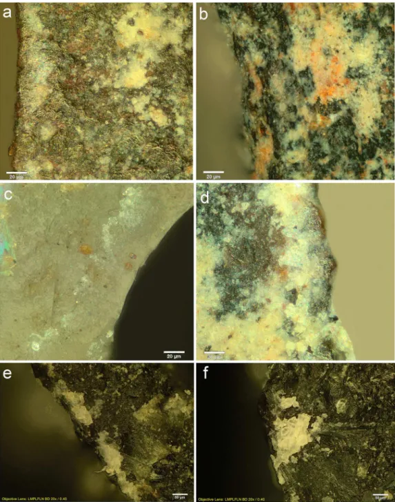
The shaping and serration flakes. In addition to the 25 bifacial serrated pieces, we also integrated the analysis of the flakes <30 mm from the sieved buckets within this study in order to sort the retouch/shaping flakes, as well as the purported serration flakes. We decided to focus only on the flakes made from quartz as it is one of the primary raw materials of the popu-lation of serrated pieces (n = 7). Also, the visibility of technical damage is more clearly visible Fig 10. Examples of residues related to pressure flaking with bone. Retouch residues on: a) the dorsal left
distal edge of 551 (x500, dark field); b) the dorsal left distal edge of 1021 (x500, bright field); c) the dorsal right medial-proximal edge of 1803 (x500, bright field); d) the ventral left medial edge of 875 (x500, dark field); e) and
f) examples of bone retouch using pressure flaking from comparative reference material (f after washing) (x200,
dark field).