ACTIVE MICROGRAVITY VIBRATION ISOLATION USING PVDF POLYMER PIEZOELECTRIC ACTUATORS
by
DAVID SCOTT STAMPLEMAN B.S., Massachusetts Institute of
(1986)
Technology
SUBMITTED IN PARTIAL FULFILLMENT OF THE REQUIREMENTS FOR THE DEGREE OF
MASTER OF SCIENCE
IN AERONAUTICS AND ASTRONAUTICS
at the
MASSACHUSETTS INSTITUTE OF TECHNOLOGY February 1991
© Massachusetts Institute of Technology,
Signature of Author
1991. All rights reserved
Department of /Aeronautics and Astronautics January 22, 1991
Certified by
Professor Andreas H. von Flotow Thesis Supervisor, Department of Aeronautics and Astronautics
Accepted by
ProVessor Harold Y. Wachman Chairman, Departmental Graduate Committee
MASSACHUSETTS ".'STI UTE OF TECHNOLOGY
ACTIVE MICROGRAVITY VIBRATION ISOLATION USING PVDF POLYMER PIEZOELECTIC ACTUATORS
by
DAVID SCOTT STAMPLEMAN
Submitted to the Department of Aeronautics and Astronautics on January 22, 1991
in partial fulfillment of the requirements for the Degree of Master of Science in Aeronautics and Astronautics
ABSTRACT
Scientists want to take advantage of the near zero gravity environment of space, because sensitive products manufactured on Earth are distorted by its gravitational force. Although in low earth orbit the magnitude of the distorting forces is not zero, it decreases dramatically to one millionth of Earth's surface gravity, a microgravity. The mounting structure for the processing facility must be able to isolate it from the additional spacecraft disturbances which dominate at frequencies above 0.01 Hz. Passive isolation is not sufficient because the likely minimum umbilical cord stiffness of 2 N/m prevents the system resonant frequency from getting this low. Active isolation is only needed between 0.01 and 5 Hz if an active soft mount approach is taken. The mount is made as soft as possible to take advantage of high frequency passive isolation and only has to be active in the above frequency range. The mount must be able to overpower the umbilical cord in order to negate the forces transmitted to the microgravity facility.
A laminated piezoelectric actuator mount has been developed for microgravity isolation. Laminated piezoelectic actuator theory is presented along with the technology developed to make the actuator a reality. The equations are specialized for laminated arc actuators. The pure mechanical dynamics were close to prediction while the arc piezoelectric response was shown to be predictable only to an approximate level. Nonlinear behavior was also observed due to the geometry of an expanding arc. Ways were found to design around these and other problems inherent to the laminated piezoelectric polymer actuator. The final mount used in the experiment consists of six semicircular laminated PVDF arcs each clamped at one end to the spacecraft and hinged at the other end to the payload. A microgravity environment sufficient enough to verify the properties of the PVDF laminated arc actuators was simulated using an air table and measured with
accelerometers; but it was not quiet enough to perform a control experiment that demonstrates absolute performance. The mount has an approximate stiffness of 10 N/m and can overpower itself and the umbilical cord for displacements of at least 2.5 mm. These are the minimum characteristics of a satisfactory microgravity mount. The system response was also fairly close to that predicted. Laminated polymer piezoelectric actuator technology has shown itself to be a serious option for performing microgravity isolation.
Thesis Supervisor: Dr. Andreas von Flotow
Acknowledgements
I would like to take this opportunity to thank all of those who helped make this project and my work towards my masters degree successful. This project would not have been the same without Andy's guidance and practical advice. I have certainly learned a great deal over the last couple of years. The dedicated days and nights at M.I.T. would not have been nearly as successful without the comradery and valuable help and advice of Bob, Farla, Simon, Kelvin, and everyone else at SERC. Don and Earl's patience and expertise in helping with the construction of the lab experiment were equally invaluable. Undergraduate laboratory assistants Carl and Dan also provided many hours of quality work which were instrumental in this project's success. But most of all, I would like to thank Anne Marie, Joe, and my parents for their unwavering support through some very difficult moments; without them, this would not have been possible.
David S. Stampleman January 22, 1991
Table of Contents
Abstract.. ... 2 Acknowledgem ents...4 Table of Contents... 5 List of Figures ... 8 List of Tables ... 11Chapter One: Introduction... Chapter Two: The Problem of Microgravity Vibration Isolation in Low Earth Orbit... ... 16
2.1 Overview ... 2.2 Isolation Requirements... 2.3 The Orbital Environment... 2.3.1 Gravity Gradient ... 2.3.2 Aerodynamic Forces... 2.3.3 Solar Pressure ... 2.3.4 Man-Made Disturbances ... 2.4 The Payload/Mount System... 2.4.1 Payload/Mount Requirements .... 2.4.2 A Single Degree of Freedom Model. 2.5 Vibration Isolation Hardware... 2.5.1 Piezoelectric Actuators... 2.6 Summ ary... 16 16 17 18 21 22 22 25 25 26 33 34 36 Chapter Three: The Piezoelectric Laminated Polymer Film Actuator. 3.1 Overview ... 3.2 Basic Concepts of the Piezoelectric Laminated Polymer Film Arc ... 3.3 Arc Equations... 3.3.1 M echanical... 3.3.2 Piezoelectric/Electrical... 3.4 Node Equations... ... 37 ... 37 37 40 41 46 47 ...
...
...
...
...
...
...
...
.
..
..
...
. o. . .. o. .e.. o. . . ... oe... ... • ... ...3.5 Multi-Axis Concepts ...
3.6 Actuator Boundary/Mounting Conditions ... 3.7 Circular Arc Length Actuators of Angles Other than
180 Degrees (n radians)...
3.8 Manufacturing Procedure... 3.9 Corrections Due to Glu Layer and Etching ...
3.10 Summary... ...
Chapter Four: Experimental Issues and Design ...
4.1 Overview ...
4.2 Three-Axis Laboratory Demonstration .... 4.2.1 The Outer Box (Space Station)... 4.2.2 The Inner Box (Payload)... 4.2.3 Payload Performance Sensors ... 4.2.4 Inner Box (Payload) Suspension ... 4.2.5 Umbilical Cord and Piezo Actuation. 4.2.6 Controller Properties ...
4.3 Three Degree of Freedom Model...
... 63 ... 63 ... 64 ... 66 ... 67 ... 69 ... 72 ... 74 ... 75
4.4 Predicted Dynamic Characteristics... 4.5 Sum m ary ... ... 83
... 84
Chapter Five: Experimental Results...86
5.1 Overview ... 86
5.2 PVDF Film Arc Properties Verification ... 86
5.3 Actuator Grouping/Mounting Configuration Experimentation ... 93
5.4 Three Degree of Freedom Experimental Results ... 96
5.5 Sum m ary...107
Chapter Six: Conclusions and Recommendations... 109
6.1 Conclusions...109
6.2 Future Work and Recommendations ... 111
References ... 114 ... 50 ... 53 ...57 ... 58 ... 61 ... 62 ... 63
Appendix A: Review of Available Passive and Active Hardware ... 119
A .1 Overview ... 119
A.2 Active Isolation... Mechanical Hard Mounts ... Magnetic Mounts... Piezoelectric Actuators... Other Actuation Methods... ... 122 ... 122 ... 123 ... 124 ... 124 Appendix B.1 B.2 B.3 B: Sensor Options ... Overview... Accelerometers ... Force Transducers... Appendix C: PVDF Piezoelectric Film Properties ... 131
Appendix D: Alternative Derivation of Arc Piezoelectric Properties ... 132
-7-A.2.1 A.2.2 A.2.3 A.2.4 .... 126 .... 126 .... 126 .... 127
List of Figures
2.1 Acceleration levels desirable for materials processing (a) and
crystal growth (b) ... 17 2.2 Spacecraft in the gravitational field of one inertially
nonspherical primary body...20
2.3 Centripetal force necessary to keep an attached payload
orbiting the Earth at LEO at the same rate as the platform... 20 2.4 Acceleration levels achievable on the Space Station... 21 2.5 Spacecraft originating disturbances ... 23 2.6 Vibration isolation requirements for a microgravity isolation
mount. a) Disturbance envelope, b) Acceleration level limit profile for DC microgravity isolation, and c) The disturbance rejection profile...24
2.7 The payload/basebody system modeled as a mass attached to a rigid wall by an active spring: a) actuator not modelled, b) actuator m odelled...27
2.8 Isolation performance of the mount: a) without any active enhancement, b) with active mount turned off, c)
required performance, and d) with active mount turned on ... 28 2.9 Control loop for acceleration feedback control... 29 2.10 Root locus of the single degree of freedom spring mass system .... 30 2.11 Loop transfer function of the single degree of freedom spring
mass system with different types of compensation: a) gain feedback of acceleration, b) lag compensation, and c) lag-lead/
lag compensation... 31 2.12 Closed loop transfer function with the lag-lead / lag compensator. . 33 2.13 SIRPNT polymer piezoelectric design concept ... 35
3.1 Induced strain in a piezoelectric plate due to an applied voltage .... 38 3.2 Bending of 2 layer laminated piezoelectric sheet due to an
applied voltage...38 3.3 Configuration of layer polarity and electrical connections for
the bending of a multimorph... 39 3.4 The PVDF laminated actuator: a) A laminated piezoelectric
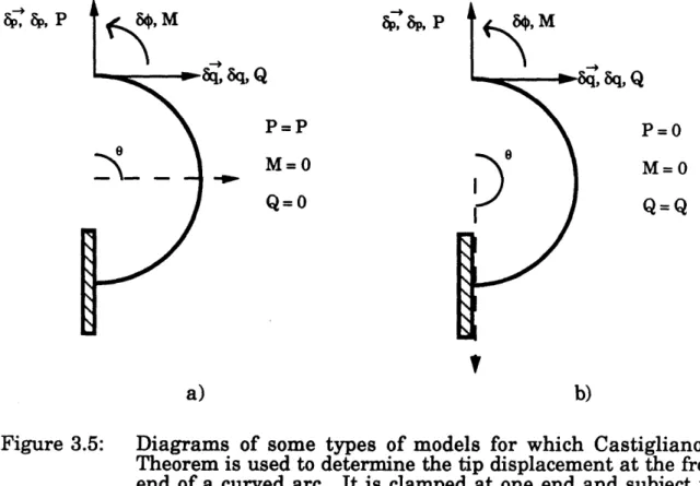
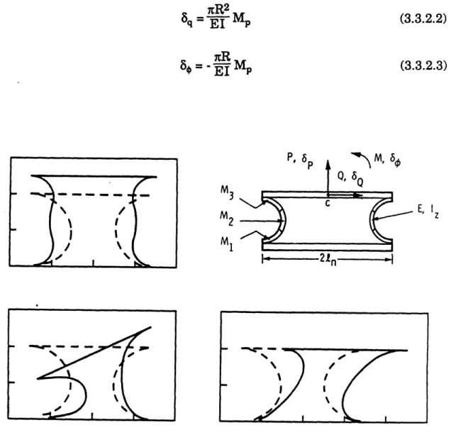
arc and b) a piezoelectric node... 40 3.5 Diagrams of some types of models for which Castigliano's
Theorem is used to determine the tip displacement at the free end of a curved arc. It is clamped at one end and subject to forces
at the free end. a) 9p direction (vertical) force and displacement. b) 4 direction (horizontal) force and p direction displacement ... 41 3.6 An actuator grouping called a node consisting of two
piezoelectric arcs back to back. The metallization on each arc is divided into three sections to allow pure side to side and
rotational motion as well as vertical...47
3.7 Solution to avoiding the undesirable effect of not giving enough space between the point of contact of the arc with the mounting assembly and the surface to which the mounting assembly is
attached: a) the undesirable effect, and b) the solution ... 50 3.8 Three degree of freedom, two node PVDF arc configuration to
control a box (square) payload ... .51 3.9 Four types of actuator mounting configurations using hinged
end conditions: a) clamped-hinged (single hinge), b) hinged-hinged (two hinge), c) clamped-double hinged-hinged type I (internal double hinge), and d) clamped-double hinged type II (external
double hinge)... 54 3.10 A node comprised of arcs mounted by hinges at each end with
the arcs given opposite commands... 56 3.11 Displacements of hinged circular arcs. Arcs with arc angles of
more than 180 degrees can move further... 57 3.12 Illustration showing how a slight mis-alignment of the layer
edges necessitates a 1 to 2 mm border on each PVDF layer with the metallization etched off...59
4.1 Three degree of freedom test set up...64
4.2 Accelerometer placement configuration on the inner box with the equations used for calculating the acceleration of the
payload relative to its geometric center of body... 67 4.3 Acceleration noise profile of a typical QA-1400 or QA-2000
accelerom eter...68
4.4 Inverted/non-inverted pendulum suspension system: a) single pendulum, b) complete system...69
4.5 Locus of the roots of the characteristic equation of the coupled pendulum system as the center of gravity is shifted from below the pivot to above it...71
4.6 Mounting configuration of a single hinge arc in the experim ental setup...74
4.7 Forces acting on the payload are dependent on both the
displacement of the payload and the spacecraft... 76 4.8 Analysis model of the six arc, three node, three DOF single
plane microgravity isolation experiment... 77
-9-5.1 Experimental set up for verifying the physical characteristics of a single PVDF arc. Measured quantities are also indicated... 87 5.2 The force-displacement relation predictions by the two methods
of arc property verification plotted with some experimental data: a) Vertical displacement, and b) Horizontal displacement... 91 5.3 The voltage-displacement relation predictions by the two
methods of arc property verification plotted with some
experimental data: a) Vertical displacement, and b) Horizontal displacem ent...92
5.4 Clamped end conditions for the semicircular arc result in large deviations from the assumed circular arc shape at relatively small displacement levels...94
5.5 The hinged end condition for a PVDF arc ... 95 5.6 Matrix of transmissibility transfer functions: Shaker head
motion to accelerometer motion ... 98 5.7 Matrix of transfer functions: Actuator group applied voltages
to accelerometer acceleration... 99 5.8 Matrix of transfer functions: Actuator group applied voltages
to accelerometer displacement...100 5.9 Typical measured coherence functions ... 101 5.10 Mode shapes of the inner box motion... 105
6.1 A future PVDF laminated actuator mount. Tapered beams
cantilevered to the space station are used instead of arcs ... 113
A. 1 Type of passive damping and isolation...119 A.2 Hubble Space Telescope vibration dampers and their locations
on the reaction wheels on the spacecraft ... 120 A.3 Generic gimbal mount... 123
B.1 Two spring - two mass -rigid wall model of a microgravity
facility with a soft force transducer. The PVDF mount is represented by the spring attached to the wall, the sensor by the spring between the two masses, the payload by the mass furthest away from the wall, and the intermediate box by the intermediate mass...128
D.1 Clamped-free laminated piezoelectric film beam with glue
layers ... 132
-10-List of Tables
3.1 Specifications of a clamped node using Sirlin's method ... 53 3.2 Specifications of a two arc node with hinged connections ... 58
4.1 Measured experiment dimensions and predicted mount
capabilities with glue layer corrections ... 85
5.1 Comparison of methods used to verify the arc properties ... 90 5.2 Summary of key characteristics of the three DOF piezoelectric
arc active m ount...106
C.1 Typical properties of piezo film...131
-11-Chapter 1
Introduction
1.1 Motivation/Objective
This research is borne out of a desire to improve the technology available to solve the disturbance rejection problems inherent in the deployment of payloads on large space-based platforms. Many platforms are being designed to perform a multitude of missions that have stringent requirements. 1,2,3 Unfortunately, the payloads on these platforms are subject to small but nonetheless significant environmental disturbances and more tangible disturbances caused by man and machine. Some scientists have expressed a desire to use instruments for astronomy missions which require pointing accuracies as small as a microarcsecond (pasec). Also needed are isolation facilities that limit the accelerations transmitted to a payload to less than a microgravity for crystal growth or other types of materials processing. A microgravity (pg) is an acceleration level that is a fraction (10-6) of that experienced on the surface of the earth
(one g). The space station in low earth orbit (LEO) is an obvious near term application upon which this type of research can be focused. The space
shuttle orbiter is another example. On a platform such as a space station, there are many payloads and many disturbance sources. The isolation of these payloads from any disturbance is examined as a crucial element for the success of their missions. The author's additional personal desire is to
develop and implement actual hardware in order to show its readiness and applicability for current and future use. Microgravity vibration isolation of a payload on the space station using piezoelectric polymer laminated film actuators is the fruition of this project.
One of the capabilities much publicized of the space station and other orbiting space platforms is the prospect of manufacturing products free from the distortion of Earth's surface gravity. When exposed to the near free-fall or zero-gravity environment of space, these forces are reduced dramatically. However, minute forces still exist. In LEO, small forces on the order of 10-6 of Earth's surface gravity are necessary to keep a
microgravity facility from drifting away from the platform to which it is attached or from hitting the walls of its containment area. The direction and magnitude of these forces and torques are either static or they cycle at once or twice the orbital rate of approximately 10-4 Hz. The limiting factors
are environmental forces and torques caused by gravitational, aerodynamic, solar and magnetic effects inherent to the orbital environment. They cannot be eliminated. However, many artificial, or man-made, disturbances that originate on the spacecraft do not necessarily have to be experienced by the microgravity facility. These disturbances need attenuation at frequencies above 0.01 Hz. If the disturbance is sinusoidal, this translates to a displacement of ± 2.5 mm. Ideally these disturbances could be filtered out by making the mount soft enough to act like a shock absorber. To get the corner frequency below 0.01 Hz, a stiffness of no greater that of 0.4 N/m is required for a microgravity facility of 100 kg. Not only is this very soft but it is softer than the 2 N/m supply line, or umbilical cord, stiffness likely to be necessary for the operation of the
facility. This umbilical cord stiffness still provides a fair amount of isolation but not quite enough. Active enhancement is necessary to achieve
the microgravity isolation goal. Solutions have already been formulated for this problem using magnetic mounts and air jets.4,5,6,7
Piezoelectricity is a material property such that when a material that possesses it is strained, electric charge is produced. There is a piezoelectric polarity direction to this property. When electrodes perpendicular to this direction are placed on either side of the material, the electric charge produced within the volume of piezoelectric material between the electrodes accumulates on those electrodes. This property is taken advantage of in many products such as sensors and phonograph needles.8 The converse is
also true: if electric charge is added to the electrodes encasing the piezoelectric material, strain is induced. It is this latter property which is exploited in the actuation of a piezoelectric material. There have been many applications using ceramic piezoelectric materials as actuators because of the high extensional modulus and forces that result.9,I0
Piezoelectric polymers are much softer than ceramics and the forces resulting from the piezoelectric strain are correspondingly lower. This tends to limit polymer piezoelectric materials to applications of lower force
has over ceramic material is that it is capable of larger strain magnitudes. The proposed or actual use of the active properties of piezoelectric polymers is not new but, due to the higher force capability of piezoceramic materials, the applications have been relatively scarce.8,11-16 Fortunately, the forces
affecting a body orbiting around Earth are quite small; and since the necessary stiffness of a microgravity mount is small, and a relatively large amplitude of motion is required, PVDF film finds itself in an environment suited to its capabilities.
This document will explain the above concept in more detail, discussing the basic physics of the problem, the proposed solution and experimental design, and the actual experimental results and conclusion. Chapter 2 outlines the environmental and man-made disturbances and how they affect the microgravity facility, also called the payload. With these dynamics, a representative single degree of freedom model is devised to explore the issues involved in controlling the system intended to isolate the facility from the vibrations of the spacecraft. Using this information it is then shown why this method was chosen over other capable methods. Chapter 3 discusses the PVDF laminated actuator in detail. The chapter is a basic toolbox for use in the design of the PVDF laminated arc. It presents a method of analyzing them and suggests other approaches that might be taken for further derivative actuators. Knowledge of the actuator manufacturing procedure and its corresponding considerations is also necessary for proper design and is correspondingly included. Due to the fact that the mounting conditions of the actuator within the system is crucial to its effectiveness, different mounting configurations are presented, making use of a novel hinged end condition that improves actuator performance.
The second half of this document describes the three degree of freedom experiment performed to verify the capabilities of the PVDF actuator and presents its results. Chapter 4 details all of the laboratory and arc mounting configuration hardware. The reasons for choosing a mount consisting of six laminated PVDF arcs clamped at one end and hinged at the other are discussed; and this is followed by an analysis of the final system as a whole. The choice of feedback sensor and payload suspension were major issues in the experimental design. Although the resulting solutions are relatively simple compared to other methods considered, they
were not readily apparent. The type of sensor used for the control feedback dictates the complexity of the system. Fortunately the simplest approach, an accelerometer, is possible. Typical units of the commericially available accelerometer are capable of satisfactory resolution levels; but this resolution tests the limits of the sensors and is better than the published specifications. Satisfactory performance is achievable but it is not guaranteed for the specific units in the experiment. The search for another type of sensor is outlined in Appendix B because of its influence in the design of a microgravity mount. Chapter 5 then discusses the experimental results for a single arc, an actuator grouping of two back-to-back arcs called a node, and the complete three DOF experiment. The conclusions of this research investigating the capability of a laminated polymer PVDF piezoelectric actuator are then outlined in Chapter 6.
Chapter 2
The Problem of Microgravity Vibration Isolation in Low Earth
Orbit
2.1 Overview
Scientists want to take advantage of the so called zero-g environment of space. Materials such as ball bearings and other precision products manufactured on earth are made in an unavoidable one-g environment. These products include high quality crystals grown for many applications. Gravitational forces distort these products during manufacture. Consequently these manufacturing processes can benefit from a zero-g environment. Near zero-g environments have been produced on Earth by letting items travel in free-fall but this only allows it to be a matter of seconds in duration. Unfortunately, space is not a zero-g environment either. Although the forces may be small, they are not negligible. Gravitational, aerodynamic, solar, and magnetic forces and torques are present. The respective payload and spacecraft (also called platform) missions determine which of these factors is dominant. This chapter will explain these forces and torques but concentrate on those which dominate the zero-g isolation problem on the space station. It is these forces which hold us from isolating to below 10-6 g's (1 microgravity or 1 pg) in LEO.
This chapter will also look at the basic single degree of freedom control problem for the isolation of a space based payload from any unwanted disturbances. It will cover the dynamics of such a mission and the requirements of the hardware involved. Also included are descriptions of approaches that have been attempted or proposed. All of this information will be geared toward determining how and to what degree the acceleration attenuation levels desired by the scientists and manufacturers hoping to use such a facility can be achieved.
2.2 Isolation Requirements
The vibration isolation of sensitive payloads is a significant problem with its own characteristics. The positioning of the payload is a relatively
minor concern in that the mount must simply prevent the payload from drifting out of its designated area. The specification that is of utmost importance to a space based microgravity facility is that of the maximum allowable acceleration.4,17 Figure 2.1 shows the levels of acceleration that are considered ideal from the payload performance standpoint.4 Manufacturing facilities requirements appear to get more stringent at lower frequencies while crystal growth is not as demanding. Consequently materials processing drives the low frequency requirements envelope while crystal growth does the same for the higher frequencies. If these requirements are those desired by the potential users of a microgravity facility, it is up to the engineer to determine what levels are practical in a actual implementation in LEO. These physical limitations are explained in the following sections.
10 -3 E 1 I 10 109 10-5 10-3 10-1 101 103 Frequency (Hz)
Figure 2.1: Acceleration levels desirable for materials processing (a) and crystal growth (b).
2.3 The Orbital Environment
Many environmental forces are imposed on the dynamics of an orbiting body. Gravity is the most obvious of these forces. It governs the orbital trajectories of these bodies. If a body or multi-body configuration is not inertially balanced, the existing gravity gradient will impose a torque upon it. Gravity gradient also imposes small tidal stresses within any finite body in orbit. The reaction of the structure with the Earth's magnetic field is also a consideration when the specific design of a certain system is
Key
- aEnvetoDe of eottette ,
output ivei V c
Si EURECA /
- c U.S. Spoce Station /
attempted. This is usually an order of magnitude below that of the gravity gradient torque, however, and should not dictate the choice of mounting system. A spacecraft orbiting Earth experiences aerodynamic drag forces due to Earth's atmosphere. There will also be solar radiation pressure when the spacecraft is not in the shadow of the Earth. These last two forces act on the projected area of the spacecraft. If the center of pressure is different from the center of gravity, the spacecraft will be subject to additional torque. Two co-orbiting bodies, a payload and its spacecraft for instance, may be affected differently.
The disturbances mentioned above cycle at once or twice the orbital rate of the satellite. The orbital rate is at its highest at low earth orbit (LEO) where it is approximately 10-4 Hz. The next few sections summarize the important aspects of these forces as they relate to the choice of mounting structure. A detailed description of these disturbances and how to quantify them is given in Reference 18. A similar description characterizing these disturbances and how they affect the attitude control system (ACS) of the
Space Station is given in Reference 19.
This section will also examine the man-made disturbances that appear in a spacecraft. These disturbance forces and torques can be caused by actual astronaut movement or originate from the operation of certain equipment or machines. There will be a brief overview of these man-made disturbances; those disturbances which are likely to be of most interest will be discussed in more detail. Once the disturbance environment has been characterized, a disturbance profile will be chosen and compared to a desired disturbance limit. This will result in an isolation performance specification for a microgravity facility
2.3.1 Gravity Gradient
The classical gravitational attractive force between two point masses is
F = Gmlm2/r2 (2.3.1.1)
where, G = gravitational constant = 6.67x10- 1 1
m1,m 2 = masses of the two bodies
This comes from Newton. For a distributed body orbiting a spherically symmetric primary, the force and torque exerted by gravity upon the body is calculated as an integral over the body;
= - Gm, Rd
(2.3.1.2)
B
and also
= G- XJ A d m (2.3.1.3)
B
R
where,
r
= the force vector acting on the orbiting body ml = the mass of the primary body (earth)1 = the radial vector from the center of the primary body to an infinitesimal mass element
R = magnitude of 1 c
dm = elemental mass of the orbiting body
= the torque vector acting on the orbiting body
After executing some vector algebra and ignoring some higher order terms, one realizes that the highest torques result from an inequality of the moments of inertia along the different body axes. This occurs when the body's principal axes are not aligned with the local vertical / local horizontal axes (defined by the satellite's motion about the primary body).20
1
= (02( R- I Y) (2.3.1.4)
where, g: = the magnitude of the torque vector
Co = the orbital velocity of the satellite (rad/s) IR Iy = the roll and yaw moments of inertia
For a visual aid to understand these variables see Figure 2.2.18 In the absence of other torques, gravity gradient torques can lead to slow pitch, roll, and yaw librations with periods comparable to or longer than the
orbital rate. This will lead to periodic centripetal and tangential accelerations on the order of o)2Lqmax, where L is the distance to the spacecraft center of gravity and qmax the amplitude of the libration. These cyclic inertial forces are smaller than the static gravity gradient forces discussed in the next paragraph.
(Spacecraft) X latitude of R
8 longitude of R
Y
Figure 2.2: Spacecraft in the gravitational field of one inertially nonspherical primary body.
0 2 4
Radial C.G.
6 8 10
Offset (meters)
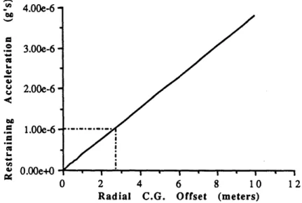
Figure 2.3: Centripetal force necessary to keep an orbiting the Earth at LEO at the same
attached payload rate as the platform.
Figure 2.3 shows the centripetal force necessary to keep an attached payload orbiting at the same orbital frequency as the basebody for a particular radial c.g. offset. This "tidal" acceleration is 0.5 milli-g (mg) per
4.00e-6
3.00e-6
2.00e-6
1 .00e-6
meter at LEO, thus at LEO a static nano-g environment is only possible when within a half of a centimeter of the c.g. of the orbiting body. Reference 19 contains figures showing ellipses that represent the gg levels achievable on the Space Station. The author's copy is not suitable for reproduction here but Figure 2.4 is an approximate version, redrawn on a computer, that illustrates the static acceleration levels achievable on the Space Station.
2
Figure 2.4: Acceleration levels achievable on the Space Station
2.3.2 Aerodynamic Forces
The basic aerodynamic force on an orbiting body as described by Hughes'8 is A S= (p aV RAp) VR (2.3.2.1) and I= epx × (2.3.2.2) A
where, VR = the unit vector of the local atmosphere
velocity vector A
VR = the magnitude of V RR
Pa = the local atmospheric density
Ap = the projected area of the satellite that the flow sees
P = the vector of the center of pressure offset from the center of mass (torque moment arm)
Aerodynamic forces may cycle at twice the orbital rate due to the bulge in the Earth's atmosphere at the equator. If the inclination of the orbit is large enough, the density of the atmosphere seen by the body will cycle twice per orbit. It should be noted that two objects in approximately the same orbit may decelerate at different rates and this difference should be taken into account when designing a mount that has to compensate for this effect. For the Space Station, the corresponding acceleration levels are about 0.25 gg directly from aerodynamic drag forces, and then another 0.1 pg from torques caused by the displacement of the aerodynamic center of pressure from the center of gravity.
2.3.3 Solar
Pressure
An estimate of the pressure exerted on the orbiting body is given by
f= psAp s (2.3.2.3)
where, pS = 4.5 x 10⁻⁶ N/m2 = the solar radiation
pressure
A
s = the vector from the sun to the orbiting body
The accuracy of this calculation depends on how well the material of the body, in this case a spacecraft, absorbs the solar radiation. The magnitude and, to a lesser extent, direction will change depending on how or if the photons rebound off of the body. For exact determination of these values see Reference 18. At LEO the solar radiation pressure is over powered by the aerodynamic and gravity gradient effects. The total environmental acceleration contribution from these forces and torques when applied to the Space Station is approximately 0.01 gg. However, as altitude increases, the atmospheric density decreases and gravitational forces become weaker. At geo-synchronous orbit (GEO) and beyond, solar radiation pressure becomes a major environmental disturbance if not the primary one.
2.3.4 Man-made Disturbances
There are also man-made disturbances in the orbital environment that must be attenuated to enable the microgravity facilities to achieve their
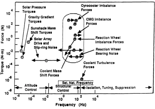
full potential. There have been various studies on the disturbance environment of an orbiting spacecraft. The types of disturbances and typical values for a generic artificial satellite are shown in Figure 2.5.21 Missing from this figure are astronaut induced disturbances such as wall push-offs and treadmill use. These peak above 10-2 Hz. (more typically at
around 1 Hz.). The induced acceleration levels can be as high as 10-2 g's. Some data has even been taken from orbiter missions, showing accelerations of many milli-g due to treadmill use.22,23 Mid deck accelerations due to astronaut treadmill usage were measured at approximately 5 mg in a frequency range of about 1 to 2 Hz. In any case, it is difficult to determine an accurate disturbance spectrum specification until the platform design is near completion. With this in mind, a sinusoidal disturbance envelope was deduced by Jones et al. and is shown here in Figure 2.6 a).4 This envelope was determined using European space station disturbance studies and correlated well with the previously mentioned disturbance studies.1 The man-made disturbance envelope
climbs above 1 gg at 0.01 Hz and marks the minimum frequency where isolation becomes necessary.
4 10 2 z 10 20
o
10 U. - 2 S10* do.4 210 o0 .6 10 1 .8 Ion -6 -4 -2 0 2 4 10 10 10 10 10 10 Frequency (Hz)Figure 2.5: Spacecraft originating disturbances 23
-Solar Pressure Cyrocooler Imbalance
Torqu Gi Tc 0* heel orces heel se - Coolant Mass Shift Forces
S Sat. Nat. Frequency
- A ttitu d e Sfid' uo'r . .. .. .... ... . .
4-An acceleration limit profile was derived from the previously stated requirements of the isolation facility users and modified according to what is possible in LEO. It too is taken from Jones et al.because of its direct applicability to the problem at hand and because of the desire to have a direct comparison with other methods (specifically, the method used by Jones et al.).4 This profile is shown in Figure 2.6 b) and when subtracted from that of the disturbance, results in a disturbance attenuation or vibration isolation profile shown in Figure 2.6 c).
101 10- 2
10 3
10.-4 10 -5 10-6
6
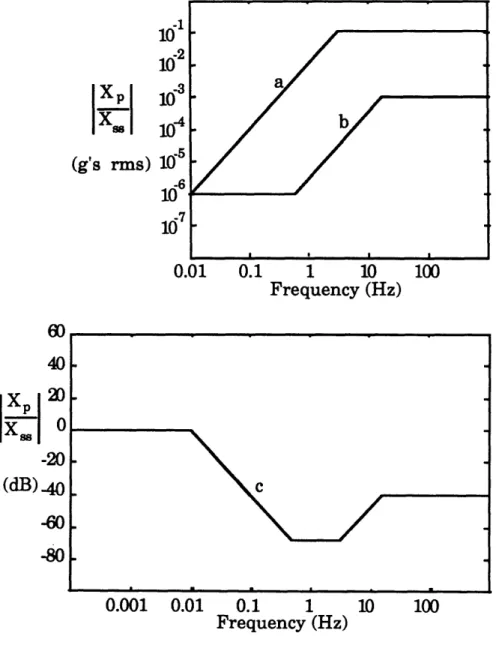
10) 0.01 0.1 1 10 100 Frequency (Hz) 0.001 0.01 0.1 1 10 100 Frequency (Hz)Figure 2.6: Vibration isolation requirements for a microgravity isolation mount. a) Disturbance envelope, b) Acceleration level limit profile for DC microgravity isolation, and c) The disturbance rejection profile.
IXP
( Ss (g's rms) 60 40 -20(dB) -40
-60 -802.4 The Payload/Mount System
The crucial mount requirement, the isolation specification (Figure 2.6 (c)) has been stated. The following section will expand upon any physical requirements of the mount that stem from this specification and those requirements that have other origins. With this in mind, a single degree of freedom model can be formulated for use as a general design tool.
2.4.1 Payload/Mount Requirements
Figure 2.6 is a sinusoidal specification from which physical meaning can be drawn. If x.. = Asincot represents the displacement of the basebody then its acceleration is xi = -Aco2sincot. Consequently, above 0.01 Hz., the mounting structure will be moving with the amplitude A which is 2.5 mm. The mount must be able to accommodate payload motion from an equilibrium position of ± 2.5 mm. The mount should also be able to isolate motions of greater amplitude since most disturbances are not sinusoidal in nature. Together with the stiffness of the mount, this displacement also yields the control force necessary to be applied to the payload in order to cancel out that which has been transmitted through the mount. The mount stiffness is a crucial factor in deciding what type of isolation scheme is necessary.
The mount stiffness is dictated by the functions it must perform. Apart from isolating the payload from the orbital disturbances power, data, and coolant flow must exist in order for the mission to be a success. These functions are the lifeline to the envisioned 100 kg payload and are labelled here as umbilical functions. The mount performs them somewhat like an umbilical cord, carrying power, data, and coolant to and from the payload. The characteristic that most affects the nature of the disturbance rejection problem is the stiffness required by this umbilical cord. The author is presently not aware of any extensive literature characterizing umbilical cords. This type of analysis has only been addressed when needed for a certain mission. The numbers used here have been drawn from the work of two microgravity isolation mount studies: Jones et al., 1987, and Gerhold and Rocha, 1987.4,7 As stated previously, the mount must transfer data,
power, and coolant between the payload and the basebody. Low stiffness data and power transfer can be achieved through wiring configurations involving coiling to achieve a soft spring. A common telephone cord helix
has an approximate stiffness of 10 N/m. Zero stiffness transfer can even be attained through non-contact methods. However, if the payload is unable to dissipate enough heat it must attach itself to the basebody cooling system. The umbilical must be able to accommodate the flow of coolant. The cost, mass, or space taken up by non-contact methods may also be prohibitive. Jones et al. derive a minimum stiffness of 2 N/m while Gerhold and Rocha design for that of 5 N/m. Beyond this apparent minimum stiffness of 2 - 5 N/m the dynamics of the umbilical cord are very uncertain. A microgravity isolation mount should be robust enough to take this uncertainty into account.
Beyond the basic isolation requirements, there are also certain characteristics that are desirable for a microgravity facility and its mount. Any piece of working space hardware should have graceful failure characteristics; it should be able to perform to a certain degree if something should partially or fully fail. There are always the ever-present concerns regarding the demands this isolation system puts on the platform as well. Space and mass are always expensive commodities in a space venture. Power usage and production costs are also a major concern. All of the above topics should be considered when deciding upon an isolation system.
2.4.2 A Single Degree of Freedom Model
When analyzing a multi-degree of freedom problem much insight can be gained by investigating a representative model that captures most or all of the major issues involved. This is no exception. A single degree of freedom model will be introduced which will guide the reader through a fair portion of the isolation method choice and ensuing design until the multidimensional factors become apparent. A multi-degree of freedom model for the three DOF lab experiment will be introduced at a later point to address the issues that may become apparent when designing a mount that will have to work in six degrees of freedom while in orbit. The system can be simplified and visualized as two masses (the payload and the platform) connected by a spring (the mount). Since the platform (approximately 200,000 kg) is extremely massive compared to the payload (100 kg), and the disturbance is specified in terms of the acceleration of the mounting interface with the basebody, it can be looked upon as a rigid wall undergoing imposed motion (see Figure 2.7 a)). We now have a simple
single degree of freedom model that can be compared to our isolation specification.
I.,
I I
basebody
mount
payload
I I
I I
I I
a) Actuator not modelled
m Payload mass Mount stiffness Payload displacment
I I
basebody mount pay
I I
I I
b) Actuator modelled load
x Basebody (space station) S disturbance displacement f Control force (from actuator)
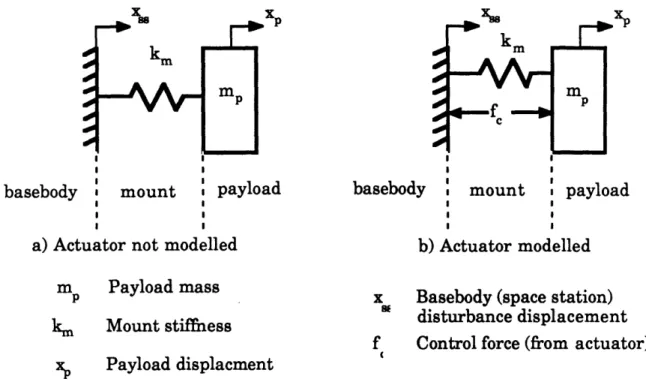
Figure 2.7: The payload/basebody system modeled as a mass attached to a rigid wall by an active spring: a) actuator not modeled b)
actuator modeled.
In summary, the system can be modeled as a mass, a spring, and a rigid wall. The mass is the 100 kg microgravity facility; the spring is the 2
-5 N/m umbilical cord/mount; and the rigid wall introduces the acceleration disturbance prescribed by Figure 2.6 a). The equation which describes the motion of this system is
mpXp + kux, = kux (2.4.2.1)
which when transformed into the Laplace domain is
(ms2+ ku)Xp = kuX.. (2.4.2.2)
and then the following transmissibility function from basebody displacement to payload displacement can be derived
-27-km
XP
X-Xp(s)
G(s
ku
Xss(s)
is
m= 2 +ku (2.4.2.3)This is also the acceleration transmissibility function because adding a multiplicative 82 term in both the numerator and the denominator is a multiplication by unity. The previously mentioned physical parameters of the system can then substituted into this equation and plotted on top of the isolation specification (Figure 2.8 a)). The nominal microgravity facility mass of 100 kg is used for mp as well as the minimum umbilical cord stiffness of 2 N/m. We can see that to meet the specification, further measures are needed in the range from 0.01 to approximately 1 Hz. If a passive system was to have the desired corner frequency of under 0.01 Hz, the mount would have to have a spring stiffness of under 0.4 N/m, which is extremely soft. A typical helical telephone cord has a stiffness of 10 to 20 N/m. The same resonant frequency can be achieved with a payload which has the mass of a garbage truck and is attached to the space station with this telephone cord. An actuation system that provides cancelling forces determined by a controller with feedback from sensors is needed only if the mount stiffness is greater than that necessary, 0.4 N/m, to keep the
60 40 20 -s- 0 xss -20 (dB) -40 -60 -80 Frequency (Hz)
Figure 2.8: Isolation performance of the mount: a) without any active enhancement, b) with active mount turned off, c) required performance, and d) with active mount turned on.
resonant frequency below 0.01 Hz.
The actuator is modeled as being in parallel to the umbilical cord or mount spring (see Figure 2.7 b)). The first two equations in the previous section then become
mpXp + kmxp = kmxss + fc (2.4.2.4)
(mS2 + km)Xp = kmXss + Fc (2.4.2.5)
where km is the composite mount stiffness of the umbilical cord stiffness, ku, and the actuator stiffness, ka. Since acceleration is the specified performance metric, a control force should in some way be based upon it. The Laplace domain transfer function, K(s), between the accelerometer and the control force can be introduced into the above equation by substituting in Fe(s) = -K(s)s2Xp(s), where s2Xp(s) the acceleration of the payload. The
equation is then rearranged so that a transfer function from Xss(s) to Xp(s) is produced. It is also shown in its block diagram form in Figure 2.9.
km
Xp(s)=s2[mp + K(s)]+kmXs(S) (2.4.2.6)
X
S1XP
Figure 2.9: Control loop for acceleration feedback control
The choice of compensator is made easily when one looks at the denominator of the above transfer function. Since the compensator only enters into this equation as an additive term in the s2 coefficient along with the mass of the payload, then if the compensator is real and positive, the effective mass of the system can be increased so that the system resonant
frequency is below 0.01 Hz (Figure 2.8 b)). This is output feedback with constant gain. The resonant frequency of the system becomes ýkm/(mp + K,), where K& is the gain of the compensator. As the gain of the compensator is increased, the resonant frequency of the system can be lowered. This can also be visualized by looking at the open loop root locus of the system (Figure 2.10 a)).
0.56 0.4 0.3 0. 2 0. 1 0 -OL 2 . -0.1 -0. 2 -0.3 -0..4 0.6 0.4 0.2 0 -0.2 -0.4 -RS -0. 6 -00 506 -0.04 -005 -0. -0. .01 0 OLl. 002 0.08 0.04 0.05 -1 -08 -0.6 -0.4 -0.2 0 0.2 0.4 0.6 0.8 1 elReal
a) Gain feedback of acceleration b) Lag compensation Figure 2.10: Root locus of the single degree of freedom spring mass
system.
This basic control concept is that of a semi-active soft mount. The high frequency isolation characteristics of a soft spring are exploited and active isolation is only used in the frequency range of interest. This approach of using actively enhanced passive microgravity isolation has already been taken on Earth with a commercially available isolation table called EVIS (Electronic Vibration Isolation System) produced by the Newport Corporation.2 4 The table surface sits on elastomeric supports and the whole system has passive resonant frequency of around 15 Hz. This corner frequency is effectively lowered to approximately 1 Hz using the proprietary sensing and isolation hardware that is at these supports. It is claimed that this system keeps vertical and horizontal accelerations of the table to as low as 3 gg rms, limited by servo noise.
For the purposes of the space based microgravity isolation problem, the frequency range of active enhancement can be seen in Figure 2.8 b). Isolation is necessary at frequencies as low as 0.01 Hz and possibly as high
--as 10 Hz depending on the composite stiffness of the mount. The sensors must achieve their desired resolutions within this frequency range. The topic of sensor choice will be discussed in a later section. However, it should be reiterated here that the acceleration of the payload should be measured with a resolution of a fraction of a gg in the crucial frequency range for gg isolation to be successful.
From the diagrams it should be apparent that additional damping may be needed to keep the system stable and prevent the amplification of the acceleration disturbance at the new resonant frequency of the system. If
104 10- 10 101 10 0 10 1y 0 Frequency (H4
a) Gain feedback
10 4 104 10 s 10'1 100 101 10 2 4 10 4 10s 101 100 101 10s Frequency (Hz) Frequency (Hz)
b) Lag compensation c) Lag-lead / lag compensation Figure 2.11: Loop transfer function of the single degree of freedom spring
mass system with different types of compensation: a) gain feedback of acceleration, b) lag compensation, and c) lag-lead / lag compensation.
one looks at the root locus diagram one can see that the addition of a real pole in the feedback loop will add damping (Figure 2.10 b)). At frequencies above the uncompensated resonance, it will satisfy the loop transfer function straight line bode plot guideline that the loop transfer function should crossover the 0 dB line (unity gain) with a slope of + 1 dB/dB in order to keep the phase margin above 45 degrees (Figure 2.11 b)). In this single DOF model the loop transfer function is K(s)G(s)/km. If additional damping is desired and the low frequency crossover is to be conditioned by the same single pole compensator, the frequency of this pole must be at least three orders of magnitude lower. This may not be necessary because the first pole seems to have adequate damping. In either case, the compensator is now no longer a constant gain compensator and leads to a much higher loop gain in the control bandwidth. Another choice of compensator is more likely since it may be difficult to maintain the necessary controller gain characteristics and at the same time control undesirable roll-off characteristics. If a lag/lead compensator is chosen to condition the low frequency crossover and provide the necessary damping, high frequency lag compensation can provide a stable high frequency roll-off (Figure 2.11 c)). This compensator also represents a practical implementation of a constant gain controller. Filters either side of the critical control bandwidth attenuate any undesirable signals that could affect performance. The transfer function of this compensator expressed in the Laplace domain is
(s + b)
K(s) = Kc+ a)(s + c) (2.4.2.7)
and the resulting closed loop transfer function, plotted in Figure 2.12, is
H(s) = kms2 + km(a + c)s + kmac (2.4.2.8)
H(s) = (2.4.2.8)
mps4 + [mp(a + c) + Ke]s3 + (mpac + Kcb)s2 + km
where a < b < jkm/mp < c.
It is also prudent to note that in order for the system to be properly modeled, the uncertainty in the dynamics of the umbilical cord must be
accounted for. In order for this to be achieved in the active mount dynamics, these uncertainties can be buried or overwhelmed by an active mount that is stiffer than the umbilical cord itself. An approximate factor of three relating the mount stiffness to umbilical cord stiffness was determined as sufficient by Jones et al.4 For a mount with an effective spring stiffness of 7.1 N/m it was experimentally determined that an umbilical cord of 2 to 3 N/m, was acceptable. Since the umbilical cord may be as stiff as 5 N/m, a total mount stiffness of 15 N/m is desirable. To allow for error margin from design to actual stiffness and because it is an order of magnitude above the minimum stiffness of 2 N/m, 20 N/m was chosen as the target mount stiffness.
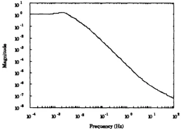
I 10* 100 10.1
10-3
0-104 10 10-7 in4 10 -4 10 10 .2 101 10 o 10 102 Frequency (Hz)
Figure 2.12: Closed loop transfer function with the lag-lead / lag compensator.
2.5 Vibration Isolation Hardware
There are many ways of achieving disturbance attenuation. Various terrestrial methods have been proposed, built, and, in a much smaller number, even applied to space based applications. The two main categories are passive and active. The merits of each type are discussed in Appendix A and the need to use active isolation is confirmed. Piezoelectric actuators are described here in the text and the reasons for choosing polymer piezoelectric material follow.
2.5.1 Piezoelectric Actuators
There are two types of piezoelectric actuators: ceramics and polymers. Both work under the same principle: a physically induced strain produces an electric charge and vice versa. The range of their actuation is constrained by their strain limits. The ceramic is stiff and brittle and thus a hard-mount. The polymer is soft enough to produce a soft spring structure. They have two very different applications.
The ceramic can produce large forces but only at small strain levels. There is a trade-off between actuator size and displacement. Displacements both angular and linear can be controlled to fine increments. When configured in stacks, an object can be positioned accurately over small ranges. This actuator becomes another vernier stage on top of a coarse actuator.2 5
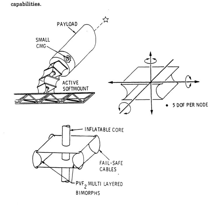
The polymer can provide smaller forces but allow relatively large displacements with small strain when used in a bimorph format. The bimorph format is where two pieces of piezoelectric sheets are attached, one on top of the other. One contracts while the other expands causing the combined actuator to bend much like a bimetallic thermostat. If configured in shelled nodal fashion as conceived at JPL, known as the Softmounted Inertially Reacting PoiNTing System - SIRPNT, it can act as a soft spring for vibration isolation and provide low bandwidth coarse pointing actuation.14-16 Please refer to Chapter 3, where the PVDF laminated actuator is discussed in detail, to get a more precise description of the principles involved. The high bandwidth fine pointing in this concept is provided by a small CMG located on the payload (Figure 2.13). Force capability of the polymer mount studied has been calculated at 0.44 N axial and 0.74 N lateral with a torque of 0.23 Nm. Deflections of 0.75 m axial, 1.2 m lateral and angles of 87 degrees have also been predicted for sub micro-radian control on a 3 meter long mount. This can also act as an umbilical cord to the orbiting payload as long as the supply lines to the payload do not overwhelm the stiffness of the soft spring mount. The stiffness of the SIRPNT piezoelectric polymer mount is approximately equal to that determined previously as the minimum necessary for soft mounting a 4000 kg payload.
The piezoelectric polymer approach is a method of vibration isolation that seems to be more than capable of fulfilling the requirements of the
microgravity vibration isolation problem. It also offers the possibility of doing so with extra desired features. The PVDF actuator can potentially allow for greater displacements than current magnetic mounts and has the added benefit that if the control system fails, there still a high degree of isolation provided by the soft PVDF arc springs. Piezoelectric polymer actuator technology is at a relatively undeveloped stage and is certainly worth more detailed study and an attempted terrestrial demonstration of its capabilities.
L)
ODE : CORE -SAFE LES r vr2 IVMULII L YEEUT BIMORPHS2.6 Summary
This chapter has outlined the physical requirements and limitations of a 100 kg. space based LEO microgravity vibration isolation facility. It also defines the general approach taken toward the design of a workable demonstration. The mount must isolate the payload according to a prescribed basebody acceleration disturbance spectrum shown in Figure 2.6. This isolation specification requires that the mount accommodate a payload travel of at least ± 2.5 mm relative to the basebody. Since the umbilical cord functions of the mount dictate a minimum stiffness for the mount too great for purely passive isolation, 2 - 5 N/m, active control is necessary. A typical regulator approach is taken to the control design and the compensator is essentially that of constant gain feedback of acceleration with a few additions to take into account potential undesirable behavior of the system outside its control bandwidth of 0.01 to 1 Hz.. It must also be taken into account that the umbilical cord part of the mount has uncertain dynamics and, in order for the control approach to work, its uncertainties must be buried by the dynamics of the remainder of the mount, the actuator. This results in a target composite mount stiffness of around 20 N/m. Piezoelectric polymer laminated arc actuators were chosen for development for several reasons: their theoretical ability to perform the aforementioned mission, the possibility of providing a greater range of motion than magnetic mount options, and their ability to provide a fair amount of passive isolation even in the event of a control system failure. There is also the need to perform a physical demonstration of these capabilities as an alternative to magnetic mount technology which has already essentially been proven capable for this the mission (although not yet flown).
Chapter 3
The Piezoelectric Laminated Polymer Film Actuator
ai
Overview
This chapter will cover the basics of a piezoelectric laminated polymer film arc actuator, from theory to manufacture. The equations describing the dynamics of a piezoelectric arc are derived as well as those for an actuator configuration known as a node. A node consists of two arcs which are placed back-to-back between the two surfaces to be isolated. Various types of arc end mounting conditions and multiple arc
configuration options are discussed. The chapter then finishes with a description of the manufacturing procedure for a laminated PVDF film arc. Included in that section are some issues which effect the mount design. This chapter is a basic toolbox for designing a PVDF laminated arc mount.
3.2 Basic Concepts of the Piezoelectric Laminated Polymer Film Arc
A piezoelectric material is one which produces an electric charge when mechanically strained or produces mechanical strain when an electric field is applied across its electrodes.s The raw material is
comprised of small portions that are electrically polarized in different directions. When a large enough electric field is applied across the material, the polarities are forced to line up. After this polarization, when a voltage less than the depoling voltage is applied across the electrodes in the poling direction, an electric field results (E=V/t) and the material will strain. If the material is a thin plate (see Figure 3.1) and the polarization is in the thickness, 3, direction, the major dimension changes will be in the plane of the plate, the 1 or 2 directions. The piezoelectric constant, d31 or d32
(the first subscript refers to the direction of polarization and the second to the axis of the resulting strain) relates electric field to induced strain. In
the case of PVDF, some properties of which are listed in Appendix C, the d31 is an order of magnitude greater than the d32. This means that when a
voltage is applied through the thickness of the plate most of the noticeable strain will take place in the 1 direction.
2 --- N
00
1
,
:
30 A/0'0 1 00 00 ------- ---- --- 1Sindicates
direction of electrical polarization Figure 3.1:Figure 3.2:
Induced strain in a piezoelectric plate due to an applied voltage
Bending of 2 layer laminated piezoelectric sheet due to an applied voltage.
If two plates or sheets are affixed parallel to each other so that they strain in opposite directions when a voltage is applied, the corresponding unit will experience a bending moment and bend much like the way a bimetallic strip bends in response to thermal strains (see Figure 3.2). If the unit is a cantilevered beam with an applied voltage, the bending strain and moment produce a tip displacement.
3d31L2
S 4hL
v (3.2.2)Mp is the piezoelectric bending moment, b is the width of the laminate (2 direction), hL is the layer thickness, E is the Young's Modulus (2 x 10⁹ N/m2), the piezoelectric constant, d3 1, is 23 x 10-12 strain per V/m, V is the
applied voltage, L is the length of the beam and 8x is the tip displacement. If more than one pair of layers are glued together, a multimorph has been assembled. If they are configured so that all the layers on one side of
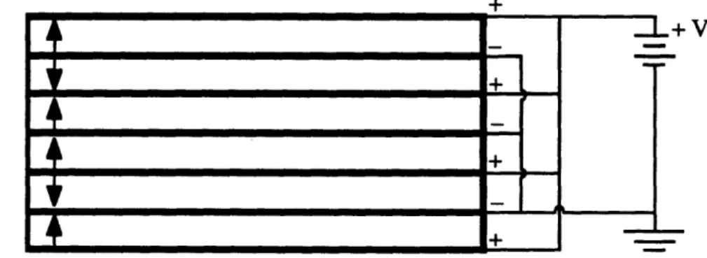
the neutral axis expand while the others contract, it too will bend (see Figure 3.3). A multimorph is useful because there is a limit to the strength of the electric field that can be applied across a piezoelectric material without it depoling. Consequently, the same electric field can be achieved by applying a smaller voltage across a large number of thinner layers. The resulting moment is
Mp = EbhLnB2d3lV (3.2.3)
where nB is the number of pairs of PVDF layers in the laminate.
4
Figure 3.3: Configuration of layer polarity
the bending of a multimorph and electrical connections for
When a multimorph is laid up on a mold so that its equilibrium shape is that of an arc, the electrically induced moment will change the radius of curvature (see Figure 3.4 a)). Thus when a voltage is applied to a
+
I.-semicircular piezoelectric laminated arc, the direction of its tip displacement is now approximately in line with the chord drawn between the arc ends. The semicircular arc also acts like a spring when mechanically compressed in this direction. This actuator now resembles an active spring. When two arcs are placed together as shown in Figure 3.4 b), the side to side motion caused by each arc folding or unfolding can be eliminated because the arcs are constrained to move together. If both arcs expand at the same time, the node will either move freely (producing a displacement) or provide a force when the movement is opposed. This is a version of the node developed by Sirlin and Laskin.15 The dimensions or
forces of the node can be commanded so that the isolation specifications are met and the only force between the payload and the basebody is that of the stationkeeping bias force.
1 cm.
umbilical
.. . -cord
Figure 3.4: The PVDF laminated actuator: a) A laminated piezoelectric arc and b) a piezoelectric node.
3.3 Arc Equations
The method of derivation of the piezoelectric actuator equations in the following sections is that suggested by Sirlin and Laskin.15 The first section
derives the mechanical stiffness of a PVDF film arc and the second derives the equations necessary to determine the actuation capabilities of the piezoelectric film arc. These two sections set up the basic equations necessary to analyze any configuration of semicircular piezoelectric arcs between the payload and the platform. The method used to analyze this type of arc is also directly applicable to actuators of different arc angle or shape. This is not the only way of deriving equations for this use. Another method,