Aero-Assisted Orbital Transfer Vehicles Utilizing
Atmosphere Ingestion
by
THOMAS JOHN MCGUIRE B.S. Aerospace Engineering Pennsylvania State University, 1999
Submitted to the Department of Aeronautics and Astronautics in partial fulfillment of the requirements for the degree of
MASTER OF SCIENCE at the
MASSACHUSETTS INSTITUTE OF TECHNOLOGY June 2001
@ Thomas J. MGuire, 2001. All Rights Reserved.
The author hereby grants to MIT permission to reproduce and to distribute publicly paper and electronic copies of this thesis
document in whole or in part
A uthor ... , ... Department of Aeronautics and Astronautics
n- / June 8, 2001
Certified by
Certified by
.... ... ... ...
Raymond Sedwick Research Scientist in Department of Aeronautics and Astronautics Thesis Supervisor
... ... . . . ... David W. Miller Associate Professor of Aeronautics and Astronautics I irector of the MIT Space Systgms)
poratory
Accepted by ...MASSACHUSETTS INSTITUTE OF TECHNOLOGY
SEP 11 2001
... Wallace E. Vander Velde Professor of Aeronautics and Astronautics Chair, Committee on Graduate Students
Aero-Assisted Orbital Transfer Vehicles Utilizing Atmosphere Ingestion
by:Thomas J. MGuire
Submitted to the Department of Aeronautics and Astronautics on June 8, 2001 in Partial Fulfillment of the Requirements for the Degree of Master of Science in Aeronautics and Astronautics.
Abstract
The atmosphere present in low Earth orbits can be used to provide working fluid to an electric propulsion system. As the craft plows through low Earth orbit (-175 - 225 km), incident gases are collected, ionized and routed through a high power electromagnetic thruster. A spacecraft utilizing this concept can generate thrust without expending on-board propellant. The performance of the system is explored in this thesis. An example mission of interest, orbital transfer of communications satellites from low Earth orbit (LEO) to geostationary Earth orbit (GEO) is presented and compared to the state-of-the-art techniques and a proposed solar thermal orbital transfer vehicle from the Boeing company. Performance increases possible with this system include lower cost per kilogram to the higher orbits, smaller and more cost effective launch vehicles for a given payload, and threefold increases in GEO capability of current launch vehicles.
In support of this concept, a large intake 'scoop' is required. Of the various options available, a solid hypersonic intake appears to be the simplest near-term option. The drag characteristics and low-density, high speed-ratio flow (speeds much greater than thermal speed) behavior around a solid-walled scoop is explored via a kinetic approach. A particle-in-cell method is used to model particle motion in a density and velocity field. The effects of surface interactions and collisions between neutral particles are treated with a Monte Carlo model. The general flowfield behavior is presented via density maps and velocity plots. The general scaling of the system drag, drag coefficient, and capture ratio are presented with variations in the cone angle of the scoop, intake radius, and assumed variables. The fine structure of the flow field is resolved within the limits of available computing power, showing a 'fuzzy' shock wave and weak bowshock effect. The last contributions of the model are drag and mass-capture values for a proposed reusable orbital vehicle.
Using the mission study and the scoop model, a high-level conceptual design of a reusable orbital transfer vehicle is presented. The proposed vehicle features a modestly-sized inflatable intake, 100 kW nuclear power source, and a spacecraft bus capable of years of operation. The mission consists of ferrying payloads from low Earth orbit to primarily geostationary orbits. The cycle time for conventional payloads is 4-5 months, allowing for many missions per year. The estimated revenue has the potential to be lucrative if development and operation costs are manageable.
Thesis Supervisor: Raymond Sedwick
Acknowledgments
I'd like to thank the American people for funding my graduate education.
To my advisor, for supporting my creativity.
To the DOD, for caring enough to believe in the future. To MIT, for finally accepting me.
To my friends, for distracting me, thus making this go faster. To Boston, for a change of scenery.
To our ancestors, for freedom. To God, for choice.
Life, opportunity, happiness, discovery, for all these reasons and more,
Table of Contents
Abstract... 2 Acknowledgements ... ... -- -- - ... 3 Table of Contents...-.-... 4 List of Figures... ... 6 List of Tables... ... ...8 Chapter 1: 1.1 1.2 1.3 1.4 Introdu ction ...-....---.---- ----.--- .--- 9State of the art spacecraft propulsion ... 9
A dvanced electric propulsion ... ... 12
Propellantless propulsion ... 17
Aero-assisted Orbital Transfer Vehicle, AAOTV...22
The Concept...22
Sizing the scoop ... 24
Heat transfer concerns ...- -... ... 24
Comparison to electric propulsion ... 25
Mission applicability ... ... 26
M ission architecture cartoon ... 28
Overview...28
Chapter 2: Mission Studies ... 29
2.1 Method of analysis ... 29
Param etric analysis and optimization...29
2.2 Orbit raising model ... 36
Derivation of cut-off time... .- ... 36
Variation of design atmospheric density and altitude...40
Variation of battery capacity...42
Variation of burn duration...45
2.3 Idealized orbital transfer vehicle study...46
Ideal single-use mission ... 46
Ideal reusable missions ... 49
2.4 Remarks and motivation for scoop work ... 51
Chapter 3: 3.1 3.2 3.3 Scoop Options ... 53 Introduction ...--.... 53 Electromagnetic scoops...53
Shock structure based scoops... . ... 55
Chapter 4: Scoop Modeling...57
4.1 Introduction ... ... 57
4.2 Flow regime ... ... 57
4.3 Hypersonic continuum model ... ... ... 62
Free-m olecular flow ... 65
Transition regime... ... 68
A lgorithm ... 72
Im plem entation ... 75
Validation of number of particles per cell...82
Validation of grid size...84
Flat plate flow validation test case...87
Perform ance...92
General behavior results ... 92
Parametric relations...94
Chapter 5: Orbital Transfer Vehicle Design Studies...104
5.1 Introduction ... 104
5.2 Near-term reusable conventional payload system...104
5.3 Scoop design and sizing...106
5.4 Scoop controllability and attitude control system sizing...109
5.5 R everse thrust ... 112
5.6 Results... 114
5.7 Technical issues and potential future work ... 115
Chapter 6: Summary... 117
6.1 C hapter sum m aries ... 117
6.2 Conclusion... 119
Appendix: Matlab Code for Flow Model...121
List of Figures
Chapter 1, Introduction:Fig. 1.1, Bussard's electrostatically deflected intake ... 18
Fig. 1.2, AAOTV configuration ... 23
Fig. 1.3, Mission profile of a reusable Aero-assisted Orbital Transfer Vehicle, A A O T V ... 28
Chapter 2, Mission studies: Fig. 2.1, System D iagram ... 30
Fig. 2.2, Optimal radius vs. power for different drag coefficients ... 33
Fig. 2.3, Maximum force vs. power over different drag coefficients...34
Fig. 2.4, Optimal exhaust velocity for different drag coefficients ... 35
Fig. 2.5, Apogee progress for 100 kW systems optimized at different altitudes ... 37
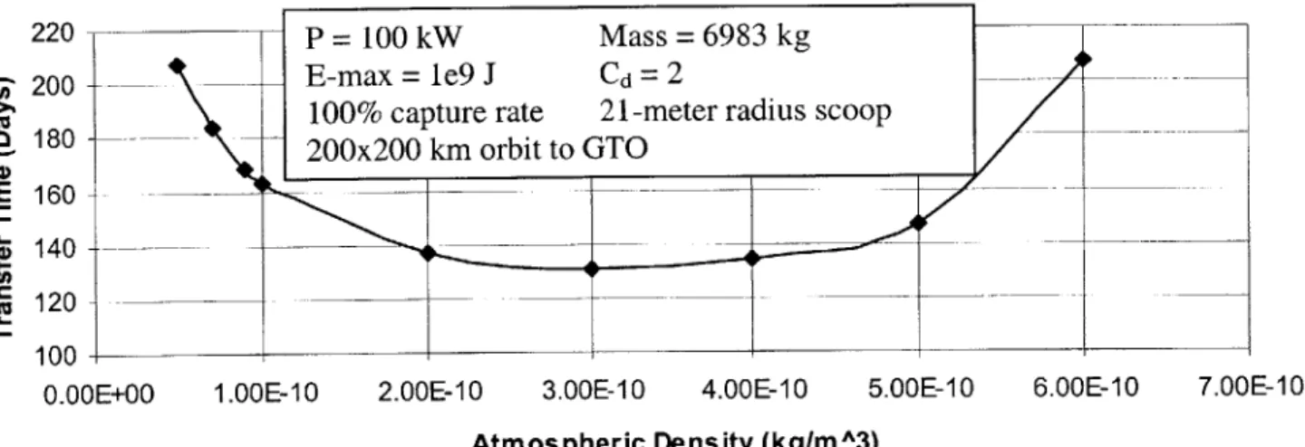
Fig. 2.6, Scoop radius and transfer time vs. density with optimally sized scoops at each density... 40
Fig. 2.7, Transfer time vs. density with fixed dimension scoop...41
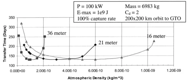
Fig. 2.8, Transfer time vs. density with various fixed dimension scoops ... 42
Fig. 2.9, Transfer time versus energy storage capacity...44
Fig. 2.10, Apogee Radius vs. Time for limited capacity energy storage, 1.5e9 J...44
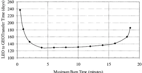
Fig. 2.11, LEO to GTO transfer time versus maximum engine burn time...45
Fig. 2.12, Altitude of perigee versus time during orbit circularization to GEO, 35,870 km ... 47
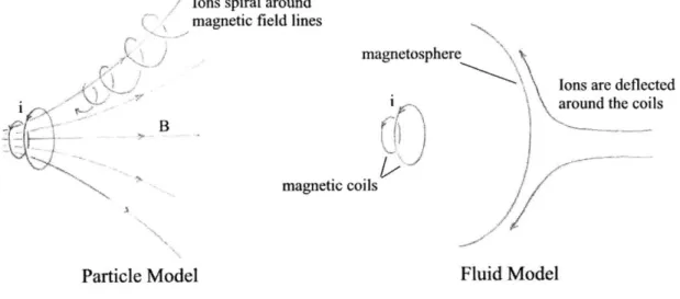
Chapter 3, Scoop options: Fig. 3.1, Particle vs. fluid models describing flow around solenoids ... 54
Fig. 3.2, Gridded ion engine concept, laser ionization shown in left box...55
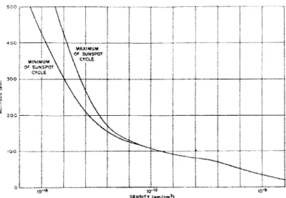
Chapter 4, Scoop modeling: Fig. 4.1, Average daytime atmospheric densities at the extremes of the sunspot 31 cycle3 ... . 58
Fig. 4.2, Fractional composition of the atmosphere (0, N, 02, and N2) as a function of altitude at the extremes of the sunspot cycle3 1... . . . . 59
Fig. 4.3, Mean molecular mass as a function of altitude at the extremes of the 31 sunspot cycle3 ... 59
Fig. 4.4, Difference between diffuse and specular reflection...60
Fig. 4.5, Shock wave structure for low-density flows... 63
Fig. 4.6, Collisionless specular reflection in a cone-shaped intake ... 66
Fig. 4.7, Parabolic intake for free-molecular flows ... 67
Fig. 4.8, Possible collisionless particle paths for a cone-shaped intake...67
Fig. 4.9, Diagram of hard-sphere collision model...70
Fig. 4.10, Flowchart of DSMC-PIC algorithm...73
Fig. 4.11, Computational space (control volume)... 76
Fig. 4.12, Throat-imposed time step limitation...81
Fig. 4.13, Drag coefficient and percentage error versus average number of particles per cell ... 83
Fig. 4.14, Drag Coefficient and percentage error versus grid size in meters...85
Fig. 4.15, Density contour and collision density contours for a coarse and fine grid, 3 meters and 1 meter square. ... 86
Fig. 4.16, Density contours around a spherical spacecraft normalized to incoming gas density, modified from Al'pert3 7... . . . ... . . . 87
Fig. 4.17, Particles impacting a flat plate at an angle of attack... . . . ... . . 88
Fig. 4.18, Numerical results for a flat plate with and without collisions...89
Fig. 4.19, Density contour maps for flat plate validation case ... 91
Fig. 4.20, Drag time history for flat plate validation case...91
Fig. 4.21, General scoop behavior...93
Fig. 4.22, Oblique shocks extending into flow... 94
Fig. 4.23, Computational space for the parametric study...94
Fig. 4.24, Capture percentage versus angle...96
Fig. 4.25, Drag coefficients versus angles...96
Fig. 4.26, Capture percentage versus compression ratio...97
Fig. 4.27, Drag coefficient versus compression ratio...98
Fig. 4.28, Power law fits for drag coefficient, Cd, and capture percentage, % ... 99
Fig. 4.29, Density map for T = 300 K scoop...101
Fig. 4.30, Velocity magnitude contour map for T = 300 K scoop...101
Fig. 4.31, Time history of computation of T = 300 K scoop...102
Chapter 5, Orbital Transfer Vehicle Design Studies: Fig. 5.1, Orbit raising model for percentage capture...105
Fig. 5.2, Scoop sizing geom etry...106
Fig. 5.3, Scoop structural support...107
Fig. 5.4, Strut w all elem ent stresses...108
List of Tables
Chapter 2, Mission studies:Table 2.1, Performance metrics at optimum scoop area ... 34
Table 2.2, Energy storage systems and considerations ... 43
Table 2.3, Ideal single-use mission mass budget ... 48
Table 2.4, Time budget for two reusable missions ... 50
Chapter 4, Scoop modeling: Table 4.1, Variation of particles per cell tests...83
Table 4.2, Results for the variation of grid size tests ... 85
Table 4.3, 2-D drag coefficients for a flat plate at different densities (collisionality)... 90
Table 4.4, 2-D drag coefficients for a flat plate ... 92
Table 4.5, Parametric study raw results ... 95
Chapter 5, Orbital Transfer Vehicle Design Studies: Table 5.1, Realistic, near-term reusable AAOTV mission performance ... 114
Chapter 1
Introduction
1.1 State-of-the-art spacecraft propulsion
The value of all the world's commercial satellites each year for the next four years will be
greater than 10 billion dollars2. That value is spread over about 125 satellites each year, and half
of these satellites are launched to Geostationary Earth Orbit (GEO). The launch cost of GEO
satellites is a large percentage of the capital outlay of satellite programs. The launchers are
expensive, and inefficient propulsion schemes have something to do with this. This thesis
explores an improved method of propulsion that will allow smaller, less-expensive launch
vehicles to do the job of the current behemoths. The motivation of this study is the huge market
of about 60 satellites traveling to GEO each year for the conceivable future. A better system
could potentially be very profitable and lower the costs associated with space launches in
general.
Most GEO satellites are relatively massive and primarily used for communications
(known as ComSats). The mass of these birds ranges from 1,000 to 4,500 kg, while the most
common sizes are about 1,500 and 3,500 kg. Typically, these are high power systems (5-10
kW), due to the power needed to communicate over the large distance from the Earth's surface to
these satellites are launched into an inclined geostationary transfer orbit (GTO) and use a solid rocket motor to achieve their final orbit. This is a high delta-V maneuver (about 1,600 meters per second) and the fuel needed is a large fraction of the total spacecraft mass (40%). Thus, an average satellite is worth 100's of millions of dollars, but almost half of its mass (all of which you pay for) is used just getting to orbit.
The launchers that are used for GEO ComSats are expensive. The most common way to get a satellite to GEO is to buy a flight to GTO on an Atlas, Ariane, Proton, Zenit or Delta rocket1. The least expensive of these is Boeing's Delta 3, which can launch 3,800 kg to GTO for about $53 million per launch. The Ariane series can launch multiple satellites, but cost per satellite is still on a par with other systems. There are other similar options, such as China's Long March line, which has seemed to recover from a string of failures, and Boeing's Sea Launch, which can launch 4500 kg to GTO from a converted ocean oil-drilling platform. But the costs for these launches are still high, $50 million for a Long March CZ-2E launching 3,370 kg to GTO and $90 million for a Sea Launch of 4,536 kg to GTO. The one relatively inexpensive option is the Russian Soyuz U, which can launch 7,000 kg to low earth orbit (LEO) for $20 million. If on-board chemical propulsion is used to achieve GEO, the Soyuz could compete for the smaller class of commercial satellite launches. An important fact to note is that a given launch system can launch quite a bit more mass to LEO as compared to GTO. GTO is a higher energy orbit and the launch vehicle has to give a GTO payload more 'kick', which means the payload has to be smaller compared to a payload headed for LEO.
There is a good reason to send payloads directly into GTO instead of first sending them to LEO. If we know that our final destination is GTO, and we are using chemical propulsion for the whole trip, then it can be shown that is more efficient to launch directly to GTO4. The key
assumption, however, is that chemical propulsion is used for all the delta-V. Chemical propulsion is pretty much required for the initial launch off Earth's surface, since it is the only option available today with a high enough power output (explosive nuclear launch was ruled out long ago and Iraq's supergun didn't make it through the gulf war). Once orbit is achieved, however, efficient electric propulsion engines can be used to conduct maneuvers. Keep in mind, the efficiency of space propulsion is classified by specific impulse, Ip, which is the duration in seconds that 1 kilogram of propellant can generate 1 kilogram-force of thrust. The electric propulsion schemes range in Is, from that of chemical propulsion (50-500 seconds) up to the tens of thousands of seconds for ion engines. The amount of fuel needed to perform an impulsive maneuver is given by the rocket equation:
AV
MP=M
g(1)1-e'P
m, = m0 1-e
where mo is the total mass of the spacecraft and g is the Earth's surface gravitational acceleration, about 9.8 m/s2. While the benefit of electric propulsion is reduced propellant load, the main price of using electric propulsion is the mass of the power system, which can greatly
offset the mass savings.
If we can ultimately trade chemical fuel for a power system, and come out ahead, we are one step closer to cheaper space access. So how do you answer the question, "did I come out ahead?" The answer, of course, depends on whom you ask and what their priorities are. For this study, the key metrics that are assumed to be important to users in general are final payload mass, total cost, reusability, and the time needed to field an asset. Gradually, advanced electric propulsion systems are being implemented in commercial satellite systems, but what are the
1.2 Advanced electric propulsion
In the interest of reducing propellant loads, many varieties of electric and/or magnetic thrusters have been developed. By looking at the systems that have progressed to the flight stage, I hope to show some of the limitations of these systems and provide motivation for eliminating fuel loads altogether. This introduction to electric thrusters will also serve to
introduce some of the engine system issues for the proposed AAOTV.
Perhaps the first electric propulsion concept to jump off the drawing board and into space was the resistojet. The basic concept is to heat a gas flow by passing it over a hot filament, sort of like an electric stove burner. By attaching a heater to the exhaust of a standard monomethyl hydrazine (MMH) monopropellant engine, the Isp can be increased from around 220 seconds to about 300 seconds. The MR-501B Electrothermal Hydrazine Thruster5 from the Primex Aerospace Company is such a thruster and is used on the Iridium constellation of satellites. It has an Isp between 294-303 seconds and operates on about 500 Watts. The improvement in propellant efficiency led to the adoption of this technology as the standard method to conduct North-South Stationkeeping (NSSK) on GEO Comsats for about 10-15 years, before being replaced by arcjets and ion engines about 5 years ago. The NSSK task demands about 50 meters per second of delta-V per year3, which adds up for a satellite designed to last 15+ years. Aside from some workable problems with fuel lines clogging, the only reason resistojets aren't in favor is that there are systems with higher performance now (and correspondingly lower fuel loads)4.
Arcjets are currently being used on numerous Lockheed satellites for GEO stationkeeping tasks7. An arcjet operates at higher Isp's by heating the exhaust gas with an electric arc. The Primex Aerospace Company has developed a series of hydrazine arcjets with an Isp ranging from 500 to about 600 seconds6. In fact, the first commercial satellite to use arcjets was AT&T's
Telstar 401. The increase in Isp allowed the spacecraft designers to cut fuel loads in half compared to resistojets and chemical monopropellants. The performance of arcjet systems could be increased further by reducing the molecular weight of the propellant, for example ammonia arcjets could attain an Isp of 800-900 seconds. If long-term space storage of cryogenic propellants is achieved, hydrogen arcjets could push an arcjet's Isp to 1000-1500 seconds. While this technology is still relatively simple to implement (it is compact and has a small power-processing system), the power requirements are much greater than resistojets. For example, the thrusters on Telstar 401 operate on 1.8 kW of power. For normal electric propulsion systems, the power scales directly with the Is, for a given thrust.
One very nice thing about arcjets is that the power requirements are modest in comparison to the capability of modem satellites. The main reason that arcjets aren't the answer to all our propulsive needs are that their Isp isn't high enough. If our goal is to reduce propellant loads to very small percentages of the spacecraft mass, we'll have to do better.
Hall Thrusters have been used extensively on Russian satellites for stationkeeping tasks. A Hall Thruster is a compact electrostatic ion accelerator. It has considerably better performance
in terms of Isp due to the acceleration mechanism. Instead of heat transfer, it relies on electromagnetic interactions to transfer kinetic energy directly to the exhaust beam. They can operate on a variety of power levels, from as low as 100 W to 20 kW9. For example, the BHT-HD-1000 nominally operates at 940 Watts at an Ip of 1870 seconds with 53.5% efficiency. The ISP capability of the Hall Thruster can go as high as 3,000 seconds, which means that the propellant loads can be a much, much smaller fraction of our spacecraft. With the stated Isp and available power levels, one can easily calculate the thrust of an electric thruster.
F =27P (2)
So the thrust for the aforementioned BHT-HD-1000 is only 55 mN. While we have increased Isp, we now find the dual-specters of low thrust and heavy power systems. The other very promising electric concept, ion engines, also suffer from these characteristics.
Hughes Electronics has developed kaufman-type gridded ion engines for station keeping on GEO satellites and primary propulsion for deep space missions. They can operate at very high Isp, but cannot operate efficiently below a few thousand seconds. A Xenon ion engine on NASA's Deep Space One mission (DS-1) will log over 20 months of continuous thrusting over its lifetime and a delta-V increment of about 4.5 krn/s. This is an excellent example of high-Isp propulsion enabling a mission with stringent delta-V requirements. Assuming chemical propulsion with an Is, of 450 seconds, the propellant mass would be 379 kg, or 64% of the total spacecraft mass (DS-1 full starting mass was 592 kg). Instead of this large propellant load that would be associated with chemical propulsion for this mission, only 81.5 kg of Xenon was used since the engine operates at an Isp of 3,100 seconds 0. This mass reduction lets you build much smaller spacecraft to hold the same amount of equipment.
The other main example is the XIPS engine, which was developed by Hughes Electronics Corporation, now a part of the Boeing Company. These engines are used for all station-keeping and spacecraft momentum control on their 702 bus. They operate on 4.5 kW at an Is, of 3,800 seconds. With XIPS, Boeing has reduced its propellant load by a factor of ten for these missions. These maneuvers represent a modest delta-v requirement, but it adds up to about 750 m/s over a
3
lifetime of 15+ years3
The XIPS on the 702 spacecraft can also be used to augment orbit-raising of the satellite. To do this, Boeing first launches the spacecraft into a supersynchronous elliptical orbit (24-hour
period) using traditional chemical propulsion. The XIPS engines then slowly change the eccentricity of the orbit, transforming into a circular geostationary orbit. This process takes about 6 months, and the reason is the low thrust nature of the propulsion system given the available power' 3. The benefit of waiting those 6 months is the increased payload mass. One
nice property of this method is the spacecraft remains in view of one ground station through the whole process, which greatly reduces operating costs compared to the multiple stations required for a electric-only spiral transfer orbit.
While the XIPS have been shown to be very beneficial for the Hughes systems, they have an important drawback. The time required to perform the orbit-raising mission is an important consideration. The six months that are needed to raise a larger, more capable satellite to its final orbit must be weighed against six months of lost profits for a smaller system. The limiting factor in bringing the transfer time down is the power available for propulsion. It isn't necessarily straightforward to increase the power level and thrust of the electric thruster systems. The power system has a considerable weight associated with it, which may only be needed for the primary propulsion component of the mission. Does it make sense to have an extra 10 kW of power for
the raising mission sitting idle over the 15+ year lifetime of the satellite?
This brings up the possibility of using electric propulsion to propel a 'space tug'. Consider a high power satellite with a very efficient electric propulsion system moving satellites around from orbit to orbit. Potentially, the space tug could take over the job of orbit raising for every GEO satellite. This would allow GEO satellites to only carry the power resources needed for its particular payload, while fuel loads would be minimized due to efficient ion propulsion. The GEO satellites would no longer need to be launched into a high energy, geotransfer orbit,
So what are the problems with this picture? First of all, the biggest power system on any spacecraft will be the International Space Station, which will feature a football field sized set of solar arrays producing about 100 kW. Even a modest space tug would need about this level of power. If done with photovoltaics, a large array would be needed. Solar dynamic power is a more compact option, but still requires a large, deployable reflector. Space nuclear reactors have been developed that produce 100 kW, but their use has been stymied by funding and political backlash against all things nuclear.
Another key issue is not a surprise; that issue is propellant. While high specific impulse electric propulsion allows propellant loads to be greatly reduced, one still needs propellant. A
'standard' space tug task of LEO to GEO orbit transfer is a very high delta-V mission. Not only does the craft have to expend about 5 km/s on the way 'up' to GEO, it has to spend that amount on the way back down to LEO. Now multiply that total by the number of missions to be conducted over the lifetime of the tug, say 5-10 years. Suddenly, the only way this can be accomplished in a reasonable timeframe, say a year for each transfer, is to have ridiculously small payload fractions. One answer to this dilemma is for the space tug to refuel after each mission. The space tug could refuel at an orbiting 'gas station', or each payload could carry its share of propellant on-board and transfer it to the space tug. Propellant transfer has yet to be done in space. Although Progress spacecraft have routinely docked with space station Mir for orbit-raising, the mutual propulsion is done by the Progress, not by transferring propellant from
one tank to another.
These are merely technically challenges, not deal breakers. Perhaps a refillable high-power orbital transfer vehicle is a future possibility, but what if we could do the job without worrying about propellant? Gone would be the problems associated with delta-V limiting our
mass fraction, and gone would be the nasty problem of propellant transfer. Numerous ideas have been forwarded to accomplish just this end, as we will see.
1.3 Propellantless propulsion
The quest for a dream of a massive human presence among the stars has motivated countless scientific and creative minds to dream up spacecraft that can use the interstellar medium for propellant among the stars. Indeed, one need not look all the way to the stars to realize the benefits of propellantless propulsion. The possibility of eliminating on-board propellant stores would lead to highly reusable near-earth and interplanetary transportation systems due to lower overall masses and practically unlimited operational life.
The Bussard Ramjet is the classic example of a spacecraft operating on only the 'stuff' in space. The idea is named for Dr. Robert Bussard who published a technical paper on the subject in 196014. It has been analyzed, revised, tweaked and re-analyzed over the last forty years. The basic concept consists of a large scoop to collect ambient matter, a fusion reactor of some kind, an exit nozzle, and a payload. Two major problems that have been identified with the concept are the lack of a good intake and the lack of a feasible fusion reactor.
Given that most of the interstellar matter is atomic hydrogen, a fusion reactor would most likely need to operate using a proton-proton reaction. The problem is that its reaction cross-section is very small. This makes the reactor inherently large, and for useful missions we are talking about reactors kilometers wide15. There are possible solutions that entail more complex techniques, such as using a proton burning catalytic cycle. The Carbon Nitrogen Oxygen (CNO) Bi-cycle would use trace amounts of those heavy elements to drive the size of the reactor down to 10's of meters for a 1000-ton ship accelerating at one gravity5. These types of reactors are far
beyond our current capability, but they manage to keep the Interstellar Ramjet Concept alive and within the realm of possibilities.
The second big problem is the scoop. Several methods have been proposed to collect particles over an area several hundred kilometers in diameter. One way is to build a very powerful solenoid so that charged particles will follow the magnetic field lines into the center of the intake. A. Martin has shown that while this might be feasible at relativistic speeds, the size of a magnetic intake would be on the order of 107 km at low velocities and thus not very
16
plausible
There are, of course, other ideas such as a large array of electrostatic deflection rings, which was proposed by Bussard in his original paper, (Figure 1.1). This technique would use radial electric fields to electrostatically deflect incoming particles far ahead of the vehicle, redirecting them just enough so that are collected by the reactor. Some of the problems with this include the plasma effects of the converging ions and the question of how to maintain charge neutrality. Deflection Field Ion Paths Exhaust Engine Direction of Motion Side Front
Akin to the electrostatic concept are methods where large charged bodies are used to project electric fields far ahead of the spacecraft". Other possibilities include using a very large gridded ion engine with separated grids that support a voltage gradient and laser ionization of incoming particles. While these concepts show promise in theory, we are still a long way off from performing a ramjet mission due to the complexity and size of the scoops and the lack of a workable fusion reactor.
Solar sailing is a concept that not only promises propellantless propulsion, but is feasible with modem technology and materials. The basic idea behind solar sailing is to use the momentum of light from the sun or ground based lasers to push on a large reflective sail. The force produced by the light is fairly small, so the sails must be large and lightweight. Likewise, the accelerations that result are on the order of electric propulsion systems, but could conceivably provide enough thrust to push vessels about the inner solar system with reasonable flight times (on the order of months, not years). They also present some unique options for the orbits. For instance, a solar sail could direct its force vector opposite to that of the local gravitational force vector, which would allow it to maintain a distance from the sun without orbiting. By similar thinking, it could perform other non-Keplarian orbits and could even provide enough delta-V to maneuver into a retrograde solar orbit.
Not only is this technology feasible, but a private company plans to launch the first solar sail mission using state-of-the-art materials8. The spacecraft would be a square sail with inflatable deployment booms and its payload would be the remains of deceased people. While this might be seen as a novelty mission, it will go far as a technology demonstrator. NASA has plans to eventually send a solar sail-based probe very far out of the solar system, a mission that would be very difficult and expensive to do with chemical propulsion.
The potential of solar sailing is limited by the capabilities of the material technology, difficulties in manufacturing and deployment of the gossamer structures, and the shear size of a sail needed to push payloads that would be useful for say, the colonization of Mars. Another limitation is that the effectiveness of a sail will drop as the spacecraft travels further from the sun, since the light diminishes in intensity. Eventually, solar sails may routinely be used to ferry goods between destinations in the inner solar system, but for now, the technology is not yet there.
An idea that operates similarly to the solar sail is a magnetic sail, or Magsail. Just as a solar sail reacts against light pressure, a large superconducting ring could develop a magnetic field that would react with the magnetic field carried by the ionic particle stream from the sun, better known as the 'solar wind'. The drag force can be used to generate a force in any direction except for towards the sun, much like a sailboat sailing into the wind.
Numerous papers have explored this, and it seems sensible if certain technological hurdles can be overcome19. The system is still very large, and a major concern would be the deployability of a superconducting ring with a diameter on the order of tens of kilometers. It would also require a reasonably large power supply to power up the magnetic field, not to mention the cryogenic cooling requirements of the ring. Still, superconducting cables are being developed for terrestrial power transmission2, and deployable structures will surely develop in the coming years. Potentially, Magsails could perform the same mission as solar sails, probably moving cargo around the inner solar system.
Mini-Magnetospheric Plasma Propulsion, M2P2, is a technique that operates very similarly to the Magsail, except that there aren't any rings present to support the magnetic field. Rather, the researchers working on the M2P2 project at the University of Washington envision a
cloud of plasma that carries a magnetic field2 1. The magnetized plasma would interact with the solar wind or Earth's field in a similar way to Andrews' and Zubrin's Magsail concept. The plasma is coupled to the spacecraft and transmits thrust to the vehicle. The key improvement is the elimination of the huge superconducting ring, but plasma physics is not straightforward and the scaling laws may not allow very large devices to be built. At least here, the problems aren't of scale, but of complex and undiscovered physics. Stay tuned, it might actually work as
advertised.
Electrodynamic tethers are another promising technology. By using long conductive wires, one can interact with a planet's ionosphere and magnetic field to generate forces or power. The concept was conceived by Grossi and Colombo circa 1980 and has reached the experimental phase in the US and Europe. Two shuttle missions and one free-flyer mission have been conducted and the results show promise. NASA is currently developing a mission (ProSEDS) in order to explore the technology further. This is basically how a thruster would work. A very long bare wire collects electrons from the surrounding ionosphere, a supplied potential drives them along the wire, forming a current, and that current produces a Lorentz force with the local magnetic field of Earth. The system can be reversed and the Lorentz force would then drive the electrons allowing the system to draw power from the wire. Prime missions for tethers include moving satellites around earth orbit and drag reduction of the space station.
Some of the major problems with tethers were highlighted by the flight experiments. These include deployability, instability and control issues, and unexplained physics. For instance, while one of the shuttle experiments was deploying, it arced and the wire broke due to a probable manufacturing flaw. Before it broke, the wire actually collected more current than was predicted by the models. The instabilities come into play when considering the vibration
characteristics of the system. Models predict that some of the modes are coupled to the secular disturbances of the earth, producing large, undesirable deflections of the wire, which itself can be kilometers long.
Tethers are still probably the best near-term way to get propellant-free propulsion around Earth and eventually the Sun and Jupiter, which both have large magnetic fields. While tethers show promise, they also face an uncertain future due to mostly their large size.
And that brings us to the central caveat with the methods of propellentless propulsion presented. While some of them might work, they are generally very large systems. The largest space structure we have yet built will be the International Space Station. Building something out of the ordinary is inherently risky, and there has to be a pay-off large enough to offset that risk. The AAOTV vehicle I propose here will be fairly compact, with a largest dimension of about 50 meters. The relatively small size of this concept gives it the potential to be a viable propellentless propulsion technology in the near term. The rest of the thesis discusses the system
analysis and physics of the system in an effort to evaluate its merit, good or bad.
1.4 Aero-assisted Orbital Transfer Vehicle, AAOTV The Concept
The main idea behind this study is the possibility that an orbiting spacecraft could operate a ramjet propulsion system in the thin upper atmosphere. The propulsion system is analogous to an atmospheric ramjet you would find on a hypersonic aircraft. An inlet would serve to compress the incoming gas flow and direct it into the 'combustion chamber'. However, instead of burning fuel in the combustion chamber of the spacecraft, the incoming gas is heated electrically or accelerated electromagnetically. The result is fast exhaust gases and the system
generates net thrust. The electrical energy is supplied by an on-board power supply, which could be solar or nuclear.
The spacecraft doesn't store the propellant it collects, but routes it directly into the thrusters. Since the engines can only fire when supplied with propellant, the engine can only operate when close enough to Earth (or other planetary body with an atmosphere). But what happens if and when the orbit isn't close enough, say with an altitude greater then about 225 km? The energy produced by the power sources can be stored when the engine isn't being fired, and that energy can be tapped when the engines are 'on'. The storage of electrical energy allows very high power to be delivered to the engine. So as long as the target missions spend at least some time at LEO altitudes, propellant is free for this system. That means refueling techniques are no longer needed and the spacecraft can operate indefinitely with respect to expendables.
A simple configuration is shown below in Figure 1.2:
Payload
Spacecraft Bus
Solar Array or Nuclear Radiator
Deployable Scoop
Sizing the scoop
The atmosphere is very thin at 200 km altitude, with a mean density of about 2.4e-10 kg/m3. If this region does indeed have low density, won't the proposed intake have to be ridiculously large in order to get enough mass flow for an engine? Luckily the answer is no, since orbital velocity is at least 7,500 meters/second (Mach 21+ at sea level) and even a little gas counts. At these altitudes, the atmospheric drag force is appreciable enough to cause satellites to rapidly de-orbit, so the local atmosphere is still thick enough to be important. By calculating the area needed to supply the mass flow to an electric engine from:
F = rhvou, = pvinAvou, -> A = F (3)
vout pvin
where 'p' is the atmospheric density, 'vin,' is the orbital velocity of an intake, 'F' is the force produced by the engine, and 'vou' is the exhaust velocity of the engine. For example, for
vout = 30,000 m/s, F = 50 Newtons, p = 2.4e-10 kg/m3, and vin = 8000 m/s, a square intake would
only have to be 26 meters a side. This is simplified model, but it shows that the size of the needed scoop for this type of system can be relatively small.
Heat transfer concerns
Suppose for a moment that the scoop is a solid structure. What will keep this huge structure from burning up in the atmosphere? One can answer this question by performing an energy balance on the scoop. The energy added to the scoop from atmospheric heating would be at most the total kinetic energy of the gas that hits the scoop. The energy of the impacting gas is mostly due to the relative orbital motion, which we know. It can be calculated as follows:
KE - pAvi IM 1 = 1 (4)
Power, = particle flux - - MA ---MMv2 =-- pAv(
where MM is the molecular mass of the ambient gas. The greatest velocity at which this system can pass through the atmosphere is about 11,000 m/s, known as the escape velocity. It is the perigee velocity of a parabolic orbit that has a perigee in low earth orbit and an apogee at infinity, operationally, the edge of Earth's sphere of gravitational influence (SOI). As the distance from Earth increases, eventually the sun's gravity force becomes larger than Earth's; this is roughly the distance to the SOI. The power input for this worst-case scenario is then about 200 W/m2 . The energy radiated by the scoop surface can be equated to the incoming energy from atmospheric heating.
Power = Aeo-T4 = Power7 (5)
where o is the Stefan-Boltzmann constant, 5.67e-8 W/m 2/K . Thus by assuming 'E', the
surface emissivity, the equilibrium temperature can be found. For aluminized Teflon, E is given as 0.8, which yields an equilibrium temperature of 45.8 K, very low indeed! In fact, the energy
23
input from direct sunlight is about 1,358 W/m in spaces, which is much greater than the aerodynamic heating.
Comparison to electric propulsion
Since this system is electrically powered, it will share some of the disadvantages of purely electrical systems. For instance, if the system is used to do orbital transfer, it will still take at least a few months with near-term power sources (<300 kW). An important goal of the mission studies in this report is to find out how to keep the transfer times short. The prime difference and advantage of the AAOTV is the unlimited propellant supply. A purely electrical system would require frequent refueling in order to perform many missions, but the AAOTV can
operate its whole lifecycle without being refueled. The bus would have to be reliable enough to last the lifetime of the mission without suffering fatal failures of any critical systems or gradual degradation due to long-term space exposure. This isn't unrealistic given the lifetimes of some ComSats, 10+ years.
Mission applicability
More than a few missions could benefit from using the thin atmosphere for propulsion. Perhaps the first one that comes to mind is canceling the drag on satellites due to the atmosphere. The drag reduction mission is only important for satellites with a portion of their orbit below about 500 km due to the high atmospheric density there. LEO satellites carry a significant propellant load dedicated to boosting the orbit. The main problem is the complexity of the scoop system on a relatively small, cheap LEO satellite. Other problems include the interference of an intake scoop with communications and observation payloads. The major orbiting space station, ISS, requires a significant fuel load to maintain its orbit. If that propellant load was eliminated, so would be the cost of the re-supply missions that carry the propellant. However, these space stations are massive, so a scoop would have to be pretty big, with a sizable, dedicated power source in order to boost the orbit. First-order calculations don't say that these missions wouldn't work, but the pay-off is small in comparison to the orbital transfer missions.
An orbital transfer mission consists of picking up cargo and moving it to a different orbit. The three identified here consist of picking up cargo in LEO and moving it to GTO, a lunar transfer orbit and a Martian pre-transfer orbit. In each of these, the AAOTV and payload must complete many orbits, each one raising the apogee a little bit. The most radical of these is the Mars transfer, in which the payload is carried to a transfer orbit with an apogee close to the
Earth's sphere of influence. Once released, the payload would fire on-board engines at the orbit perigee in order to obtain a trajectory leading to Mars. The AAOTV could give the Martian payload that initial 'kick' of delta-V, which would increase the amount of payload that could be carried to Mars on a given launch system. The disheartening argument against this mission is principally with the massive siza of potential Martian cargo. A heavy payload would need a long time to achieve the pre-transfer orbit with today's power systems. Also, manned missions put a premium on travel time, and time spent lingering around Earth should be avoided. This mission might be feasible for unmanned cargo if high power nuclear reactors are developed.
Well what happens, if we want to go to the moon? Since the AAOTV wouldn't have to leave the Earth's gravity well, it could potentially ferry stuff to moon, drop it off and come back for more. It doesn't seem like such a good idea for material returning from the moon, since it
would have to be accelerated to the AAOTV's speed to dock with it. That acceleration is almost the same needed to return to Earth in the first place. The same arguments against AAOTV
manned Martian travel also apply to the Lunar manned missions. So, while heavy payloads will require long transfer times, the AAOTV could provide propellentless transportation to the moon for cargo.
Since the international community has shown little interest in supporting large scale Mars and Lunar missions, this thesis focuses on something the world does seem to be very interested in, launching geostationary communication satellites. As depicted in the following cartoon, the AAOTV picks up the payload in LEO, and through perigee burns, extends the apogee of the mutual orbit of the payload and AAOTV all the way to GEO altitude. The AAOTV then releases the payload where it would fire an apogee kick engine to achieve its final, circular orbit. The AAOTV would then lower its apogee until it returns to LEO, where it could pick up another
satellite.
Launch payload into LEO
SEarth
Release payload at apogee of GTO
2)
Dock with AAOTV in LEO
KEarth 5) Payload accelerates to GEO Decelerate at perigee Lower apogee 3) Raise apogee -Accelerate at perigee 6) Payload in final orbit
AAOTV returned to LEO
Fig. 1.3, Mission profile of a reusable Aero-assisted Orbital Transfer Vehicle, AAOTV Overview
The remaining pages delve into the details of analyzing such a system. The success of the system will depend on how quickly it can move satellites from orbit to orbit and if it can do it at significant cost savings over conventional methods. The first third of the work characterizes the performance in terms of transfer times, comparative increase in payload capacity, and cost effectiveness for a generic 'scoop'. The second third explores the physics of a specific type of scoop via numerical analysis. In the last section, the solid-walled conical scoop knowledge is combined with the mission studies in order to present a workable concept and elucidate any challenges the system poses.
1)
Chapter 2
Mission Studies
2.1 Method of analysisParametric analysis and optimization
The analysis of this concept consists of formulating expressions for the thrust created by the engines in terms of all the operating parameters and then propagating the spacecraft's position and velocity through a sufficient transfer time. In order to accommodate different drag models for the intake component of drag, the thrust equations are derived generally, with drag left in as an independent parameter.
The electrical energy stored over one orbit is given by multiplying the steady power supplied by the time spent charging. The charging time is the period of the orbit minus the engine burn time.
Electrical Energym,, = (Period - At) * P (6)
The power delivered during the burn is given by,
Electrical Energystored
At (7)
at high power (MW's) for short bursts (1-5 minutes), generating high accelerations with state-of-the-art spacecraft power levels (-20 kW). This effect becomes very pronounced in highly elliptical orbits where the time to store energy is large in comparison to the burn time, resulting in power multiplication factors as high as 300.
In order to develop expressions for the performance of the system, the intake and engine are separated as follows,
Engine Intake Scoop
Exhaust
Fig. 2.1, System Diagram
From the above model, the drag on the scoop is defined by the gas momentum lost as it passes from station 'in' to '2':
D = rh(uin -u2) (8)
The power added to the beam can be equated to the difference in kinetic energy between the gas entering the engine and the exhaust gas. The mass flow is assumed to be constant and an engine efficiency, ri, is introduced.
P - (u2, -u2)
2r/ot (9)
Substituting (8) into (9), the expression for power becomes:
t 2 2 2D _D2
Put ,u2tin i n h2)
The exhaust velocity produced by the system is given by rearranging terms.
27P71 2 2D u D2
u = u. -- -u +
out In min mi 2
Note that the exhaust equation simplifies to the traditional rocket propulsion expression when intake velocity and drag are both set to zero.
A one-dimensional momentum equation gives a functional relationship between the net force on the system in terms of mass flow, drag, intake velocity, and exhaust velocity:
F = rh(uo - uin) - D (12) The force produced is given by,
F =,iI27P +u2 2Du D2
in rh mn t2 (13)
The most important measure of performance for the system is the velocity change produced by an engine firing.
F
Av =- At
where 'm' is the total spacecraft mass and the net force, F, is assumed to be constant over the entire engine bum duration, At. In order to perform a mission in the least number of orbits possible, the delta-V per orbit (per firing) should be driven as high as possible. It is useful then to examine the relationship between delta-V and the parameters of the system. First, total mass should be low and thrust should be as large as possible. The thrust depends on three parameters that are variable: bum time, mass flow, and energy delivered.
Ultimately, Equation (14) suggests that burn time should be maximized for maximum delta-V. Now, power scales as the inverse of time (7), and force scales as the square root of
power or the inverse square root of time (13). Plugging (13) into (14), delta-V varies as the square root of burn time. For low-earth orbits, ones in which most of the orbit has the desired atmospheric density, the charging time is reduced by increasing bum time. Also, if a perigee burn is desired (required for a LEO-GEO transfer), the bum time should be limited. 'Perigee burn' simply means we are trying to approximate an impulsive maneuver at perigee, so as not to raise the perigee of the orbit out of the usable portion of the atmosphere. For elliptical orbits, the time spent at low altitude in each orbit falls to the range of minutes. The system only collects mass in real-time (no storage), so the engine should discharge its energy within this tight window. The maximum discharge rate of the energy storage system then constrains the burn time. So the end all is that you want to fire the engine as long as you have atmosphere to ingest.
Similarly, how does the power level affect the performance? Keeping all else equal, the thrust and delta-V roughly scale as the square root of the power supplied. It is not an exact scaling due to the inclusion of drag terms in (13).
The mass flow is the most intriguing parameter. To increase mass flow, the intake area of the scoop would have to be increased or the perigee lowered to an altitude where the atmosphere is more dense. Increasing the mass flow will tend to reduce the exhaust velocity and increase thrust for a given power level. But the increased mass flow rate will then increase the drag on the scoop. The dependence of drag on area and density depends on the physics of the scoop. Different approaches to 'scooping' a low-density, hypersonic, rarefied gas flow will undoubtedly have different drag characteristics and scaling. Since technology for compressing the upper atmosphere is not well developed, interesting trends can be found when using a conventional, velocity-squared relation for drag.
D = pv2AC (15)
In the previous equation, the drag coefficient, Cd, is assumed to be invariant with regards to scale for this first-order analysis.
For the simple ballistic drag model above, an expression for optimal intake area can be found by maximizing the thrust (and subsequently delta-V) as given in (16) and (17). This is accomplished by taking the partial derivative of thrust with respect to area, keeping power constant, and setting equal to zero.
.5F 2RP 2 2D D 2 7rP 1 2
-puin -+ uin u + uin + pAuin 2 -- pv Cd =0 (16)
5A m t in mh 2 277P 2 2D D 2
-- puinA - +uin - -u + 2
Solving for the optimal area,
A (17)
pu 2Cd 1+
Fig. 2.3 shows the square root relation between optimal scoop radius and power, taken at a representative orbital velocity of 8 km/s and a local atmospheric density of 2e-10 kg/m3. One can see for a given power, the optimum radius is increased as the drag coefficient is reduced. The optimal area then scales linearly with power.
100
-~ . . ...
2 3 4 5 6 7 8 9 10
Power Supplied During Engine Bum (MW)
Fig. 2.2, Optimal radius vs. rower for different drag coefficients
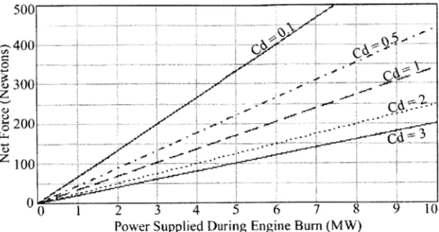
(17) into (13), the force equation. The result is shown below in Fig. 2.4. For a given drag characteristic, the optimal force varies linearly with respect to power.
500 ... ... .... ... 300 ... .-10 0 1 2 3 4 5 6 7 8 9 1
Power Supplied During Engine Burn (MW)
Fig. 2.3, Maximum force vs. power over different drag coefficients
This linear behavior shows that if the area is kept at the optimum, a system has a characteristic power specific force and area specific power for any drag characteristic, which is shown in Table 2.1. The power described here is the power the engine consumes. Also, the optimized force is positive for the whole range of powers and drag coefficients. The worst-case drag coefficient for any scoop should be around 4, which corresponds to total particle reflection. This analysis should be taken with the knowledge that the optimal area may change over a given mission, as orbital velocity, density, and available power vary.
Table 2.1, Performance metrics at optimum scoop area, uin = 8000 m/s, p = 2 x 10 '0kg/m3, T) = 0.8 Drag Coefficients, Cd Metrics: 3 2 1.5 1 0.5 0.1 Power per unit Force 49.5 40 34.8 29.1 22.5 15.0 (kW/N) Power per unit Area 1550 1024 772 528 288 85.7 (W/m 2)
produced for a given scoop area. Higher drag scoop schemes would be smaller and higher power devices.
An interesting parallel can be drawn to the modem electrical propulsion concept of optimum specific impulse for a given mission. By substituting the expression for optimum area, (17), into the exhaust velocity equation, (11), remembering mass flow is dependent on area, and simplifying, an expression for the optimum exhaust velocity is found.
1t + d(18)
Since the optimal area scales linearly with power, the ratio of exhaust velocity to intake velocity is dependent only on the drag coefficient of the scoop.
The ratio of optimum exhaust velocity to the intake velocity is plotted against drag coefficient below. 5 4 2 0 0.5 1 1.5 2 2.5 3 3.5 4 Drag Coefficient, Cd
Fig. 2.4, Optimal exhaust velocity for different drag coefficients
At very low drag coefficients, the value is slightly greater than one, since there isn't much drag to counter-act. At higher drag coefficients, the optimal exhaust velocity is higher, in order to make-up for drag. A practical limitation is that if the power is low enough, the exhaust velocity would be lower than existing ion or MPD engine capabilities. For example, at LEO orbital velocity of 7,500 m/s, and Cd = 0.5, the optimum exhaust velocity is 15,000 m/s. This issue could be resolved through engine development and/or having the system operate at
sub-optimal areas and/or exhaust velocities.
In order to take into account the variations in power, burn time, and density that would occur in a real mission, an orbit-raising model was constructed. The purpose of the model is to define the transfer time for a given mission and observe how the individual parameters affect performance.
2.2 Orbit raising model
The model uses an orbit-by-orbit approach. From an initial orbit, the orbital elements are used to calculate the orbital period. The amount of time used to store energy in a given orbit is found by subtracting from the orbital period the time in which a full orbit is under a certain cut-off altitude. This altitude represents the edge of the atmosphere in which the spacecraft engine operates. The density is taken as a constant for the burn, so this altitude should be limited to a corresponding density that is within some percentage of the design atmospheric density and altitude. For this case, +50% density was chosen, corresponding to 230-km cut-off altitude. For those orbits within the atmosphere, a maximum burn time is specified which would estimate an impulsive bum instead of the reality of a thrust arc. A more accurate model would be to vary the density and hence the mass-flow at the different altitudes and corresponding velocities. The adverse effects produced by this sub-optimal burning could possibly be compensated for by adjusting the power level supplied to the engine. So then, to first order, the burn time is the time spent under the cut-off altitude. This time is calculated for each orbit as follows.
First, the semi-major axis of the orbit is calculated,
Second, the radius of apogee is found,
Ra = 2a - R, (20)
where v, is the orbit velocity at perigee and R, is the orbit radius at perigee. Third, the eccentricity is calculated,
R- Rp =
a -R (21)
Ra + R,
Fourth, the true anomaly at the cut-off altitude, Rc, is found,
v =cosI a(1-e) 1 (22)
eRC e
Fifth, the eccentric anomaly for the cut-off point on the orbit can be found,
=cos1 e+cosvC (23)
1+e -cosv,
The mean anomaly at the cut-off point is then given by,
(24)
MC = EC - e -sin E
Lastly, the time spent on each orbit below the cut-off altitude is given by,
t = 2M 3 (25)
C~
=2M
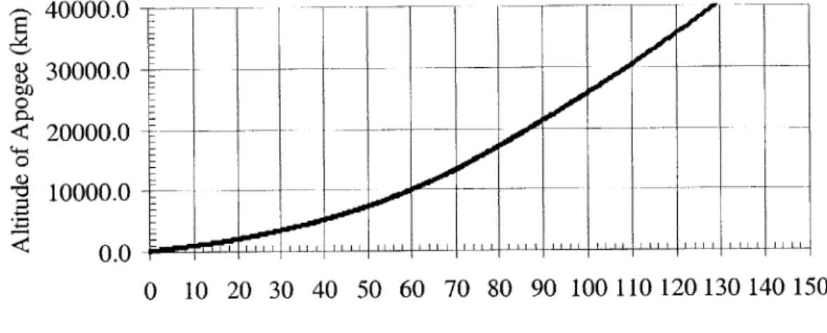
-For each orbit, the delta-V for a given vehicle is then calculated and used to increment the perigee velocity for the next orbit. The process thus steps up the apogee of consecutive orbits with time. 50000 40000 30000 20000 o 10000 0 0 10 20 30 40 50 60 Time (days)
GEO Optimal, radius = 78 m - - - - LEO Optimal, radius = 56 m
Fig. 2.5, Apogee progress for 100 kW systems with thrust optimized at different altitudes
CEOgo LEO