By
Wing Yan Alison Leung
B.Sc. Civil Engineering Queen's University, 2000
SUBMITTED TO THE DEPARTMENT OF CIVIL AND ENVIRONMENTAL ENGINEERING IN PARTIAL FULLFILLMENT OF THE REQUIREMENTS FOR
THE DEGREE OF MASTER OF ENGINEERING
IN CIVIL AND ENVIRONMENTAL ENGINEERING AT THE
MASSACHUSETTS INSTITUTE OF TECHNOLOGY JUNE 2001
@ 2001 Wing Yan Alison Leung. All rights reserved.
BARKER
MASSACHUSETTS INSTITUTE OF TECHNOLOGY
JUN 2
2001
LIBRARIES
The author hereby grants MIT permission to reproduce and to distribute publicly paper and electronic copies of this thesis document in whole or in part.
Signature of Author: ...
J
C ertified B y: ...
Accepted By: ...
epartment'df-Civil and Fqironmental Engineering May 19, 2001
.... .... . .. ... ... -- . r ... Jerome J. Connor Professor of Civil and Environmental Engineering Thesis Supervisor
.. ...
KI Oral Buyukozturk
rman, Department Committee on Graduate Studies
*go-By
Wing Yan Alison Leung
SUBMITTED TO THE DEPARTMENT OF CIVIL AND ENVIRONMENTAL ENGINEERING ON MAY 11, 2001 IN PARTIAL FULLFILLMENT OF THE REQUIREMENTS FOR THE DEGREE OF MASTER OF ENGINEERING IN CIVIL
AND ENVIRONMENTAL ENGINEERING
ABSTRACT
Wind effects on tall buildings has gained substantial attention over the years. As building materials become stronger but lighter, and understanding of the behaviour of structures advances, strength is no longer a concern in the design of tall buildings. This has
prompted an extensive improvement in structural system such as the frame structures, the tubular structures, and the outrigger structures. Besides, the high technology dampers are gaining acceptance and have been adopted in various structures. The application of passive control, hybrid control, and active control on civil engineering structures all
sounds promising.
Thank you Dad, Mom, and Sis for your unconditional care and love. Thank you for standing by me all day long and all year round. And thank you for encouraging me and supporting me to pursue my goals.
Special thanks to Professor Connor for his guidance and Ms. Grebner for her valuable comments on my thesis. Without your help this thesis would not be made possible.
TABLE OF CONTENTS TABLE OF FIGURES INTRODUCTION 1. OVERVIEW OF WIND 1.1. Behaviour of Wind 1.1.1. Types of wind
1.1.2. Extreme Wind Conditions 1.2. Characteristics of wind
1.3. Wind loadings in general
1.4. Application of wind loadings in building codes 1.4.1. Basic Building Code
1.4.2. Uniform Building Code
1.4.3. National Building Code of Canada 2. THE EFFECT AND ANALYSIS OF WIND 2.1. Effects
2.1.1. Human response to building motions 2.1.2. Sound effects
2.1.3. Lateral Deflection 2.2. Responses of Structures
2.2.1. Along Wind Response 2.2.2. Cross-wind Response
2.2.2.1. Vortex Shedding Phenomenon 2.3. Analysis Methodologies
2.3.1. Static Approach 2.3.2. Dynamic Approach
2.3.2.1. Induction of P-Delta Effect
2.3.3. Analysis Simplification and Assumptions 2.4. Types of Failure
3. GENERAL DESIGN APPROACH 3.1. Considerations 7 8 9 9 10 10 11 13 13 14 14 15 17 17 18 18 19 19 19 20 22 23 24 24 25 26 27 28 28
3.3. Preliminary Design 31
3.4. Final Design 32
3.5. Wind Tunnel 33
3.6. Design Procedures 34
4. CONTROL 34
4.1. Types of Tall Building Structures 35
4.1.1. Braced Frame 36
4.1.2. Moment Resisting Frame 39
4.1.3. Frame Truss Interacting System 41
4.1.4. Shear walls 42
4.1.5. Tubular system 43
4.1.5.1. Frame tube system 43
4.1.5.2. Truss Tube 44
4.1.5.3. Bundled Tube 46
4.1.6. Outrigger structures 47
4.1.7. Hybrid Systems 49
4.2. Passive control 50
4.2.1. Tuned Mass Damper 50
4.2.1.1. Translational tuned mass damper 51
4.2.1.2. Pendulum tuned mass damper 52
4.2.2. Water tank/Artificial Lakes damper 53
4.2.3. Friction damping 54
4.2.4. Visco-elastic material damping 55
4.3. Active Device 56
4.4. Hybrid Device 58
4.4.1. Hybrid Mass Damper 58
4.5. Semi Active Control 59
4.5.1. Variable Orifice Dampers 60
4.5.2. Controllable Tuned Liquid Dampers 62
4.5.3. Electro-Rheological & Magneto-Rheological Fluids Damper System 62
4.6. Mass Control 65
4.7. Aerodynamic shapes for the buildings 66
4.8. No control 68
5. CONCLUSION 70
REFERENCE 71
TABLE OF FIGURES
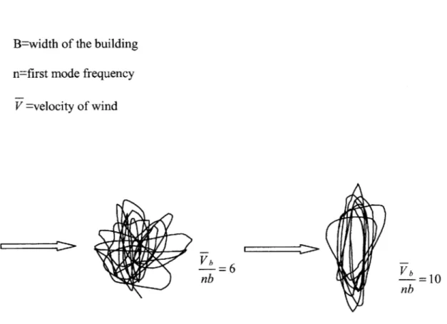
Figure 1 Displacement traces at the top of an aeroelastic model of a square tower...21
Figure 2 D esign procedure... 34
Figure 3 Concentric braced frame forms ... 37
Figure 4 Eccentric braced frame forms ... 37
Figure 5 Braced Frame Parking Structure [2]...39
Figure 6 Deformation of a moment Resisting Frame ... 40
Figure 7 Center to center connection of forms with moment connections...40
Figure 8 Deflection and shear resistance of frame-truss interacting system [2] ... 41
Figure 9 Comparison of deformation with and without shear wall system...42
Figure 10 Framed tube structure... 43
Figure 11 Bank of China Tower ... 45
Figure 12 Sears T ow er... 47
Figure 13 B ond Building ... 48
Figure 14 Location of tuned mass damper ... 51
Figure 15 Translational Tuned Mass Damper for Chiba Port Tower [1]...52
Figure 16 Crystal Building - Modified Pendulum Tuned Mass Damper [8]... 53
Figure 17 Multi-Step Tuned Mass Damper [8] ... 53
Figure 18 Friction dam per ... 54
Figure 19 Visco-Elastic Damper [11]...55
Figure 20 Locations of Viscous Dampers [11]...55
Figure 21 Active Tuned Mass Damper in Motion [8]...56
Figure 22 A ctive D am pers... 57
Figure 23 Kyobashi Seiwa Building [7]...57
Figure 24 V-Shaped HMD [7]...59
Figure 25 Variable Orifice Damper [7] ... 60
Figure 26 SHD cross section [5]...61
Figure 27 Location of SHD [5]...61
Figure 28 M R dam per [7]... 63
Figure 29 M R M aterial ... 63
Figure 30 MR fluid after being magnetized ... 64
Figure 31 Aerodynamic Modifications to Square Building Shape [3]...66
INTRODUCTION
Why tall buildings? Why wind design?
As distinctive landmarks, tall commercial buildings are frequently developed in city centers as prestige symbols for corporate organizations. Rapid growth of population and consequent pressure on limited space have considerably influenced city residential development. As well, in some areas the high cost of land and the importance of preserving land for various purposes have led to the need for tall buildings. In some cities, such as Hong Kong and Rio de Janeiro, topographical restrictions has made tall buildings the only feasible solution to satisfy the demand for housing.
Because of the height of tall buildings, it is generally more susceptible to lateral forces from wind. Most often, wind effects are the controlling factors in structural design rather than strength concerns. This causes wind effects to be a major element in determining the building shape and structure of a building, and especially in area where earthquakes are rare. Besides, daring structures constructed with lightweight but high strength
building materials have created an undeniable need to obtain a better understanding of the wind effects than that described in the codes.
1. OVERVIEW OF WIND
Wind is air in motion. It is usually used to describe the natural horizontal motion of the atmosphere, whereas motion in a vertical or near vertical direction is called a current. There are various types of wind and their natures are largely unpredictable.
1.1. Behaviour of Wind
The air moving along its path is reluctant to rise when it encounters a tall building. Whenever possible, it will prefer to flow around the building rather than over it. The predominant reason for this action is that the wind tends to follow the path of least resistance, in other words, a path that requires minimum expenditure of energy. In
general, it requires less energy for the wind to flow around the building at the same level than for it to rise, as rising requires potential energy in addition to the required kinetic energy. Also, if the wind has to go up or down, additional energy has to be expended to compress the column of air above or below it. Hence, wind tends to flow at the same level. However, during high winds when the air stream is blocked by the broad side of a tall, flat building, it has a tendency to drift in a vertical direction rather than to go around the building at the same level especially towards the top of the building. As the
circuitous path around the building causes the air particles in the center of the flow to loose more energy in total, because the additional required kinetic energy is greater than the additional potential energy. On the other hand, the wind along the sides of the flow will still tend to flow around the building. Thus the wind is driven in two directions. Some of the wind will be deflected upward, but most of it will spiral to the ground creating a standing vortex or a minitornado at the sidewalk level. [4]
1.1.1. Types of wind
Winds are categorized by their occurrence and fluctuation around the year into three types:
i. prevailing wind
ii. seasonal wind, and
iii. local wind
Prevailing winds are air masses moving from different latitudes toward the low-pressure equatorial belt. Seasonal wind is formed due to the movement of air over the land to
oceans for winter and vice versa for summer. It is the movement of air from cold region to warm region. Local wind is caused by the daily changes in temperature and pressure over land and water bodies; and suggested by its name, the effects is local. [4]
1.1.2. Extreme Wind Conditions
Hurricanes, thunderstorms, typhoons, and tornadoes, are winds which cause direct economic damages exceeding several billion dollars in any given year.
Thunderstorms often occur in temperate summer weather. It is accompanied by long hot periods together with torrential rain, with average wind speeds of 20-70 mph.
Hurricanes are severe atmospheric turbulences that originate in the tropical regions of the Atlantic Ocean or Carribbean Sea. The maximum basic wind velocity for any area of the
United States specified by code is 120 mph. This is similar to the storms, called typhoon, occurring in northwestern Pacific.
Tornadoes develop within severe thunderstorms and sometimes hurricanes. It consists of a rotating column of air which usually goes together with a funnel-shaped dense cloud having a vortex of several hundred feet, typically 200 to 800 ft in diameter and at speeds up to 300 mph. Tornadoes are the most destructive of all wind forces, usually destroying everything along its path. A typical tornado travels 20-30 mph. Due to the extremely low pressure at the center of a tornado, as the storm passes over a building, the pressure inside the structure is far greater than that outside, "causing the building to literally explode" [4]. Currently, standard buildings are not designed to withstand a direct hit from tornado. However, for those critical building, such as defense installations and nuclear facilities, sufficient information is necessary to implement tornado-resistance deign. [4]
1.2. Characteristics of wind
Wind is largely variable. It may be influenced by nearby buildings and by the landscape substantially. In general, factors identifying the characteristics of wind are:
a) wind direction b) gradient wind speed
c) maximum wind speed , and d) turbulence intensity.
Wind velocity varies with height. This is because viscosity increases towards the earth's surface and thus reduces the air velocity adjacent to the ground to almost zero. The slowing down is less at each layer and eventually becomes negligibly small as height increases. The height at which the velocity ceases to increase is called the gradient height, and the corresponding velocity is called the gradient velocity. [4]
At a height of approximately 1200 ft from the ground, the wind speed is practically unaltered by surface friction and its movement is simply dependent on the prevailing seasonal or local wind effects. In engineering practice, wind profile in the atmospheric boundary layer is well represented by the power law expression of the form [4]:
V,
=Vg(Z / Zg)awhere VJ= the mean wind speed at height Z above the ground
Vg =gradient wind speed, assumed constant above the boundary layer Z =height above the ground
Zg=depth of boundary layer, varies with terrain roughness
a =power law coefficient, varies with terrain roughness, ranges from 0.14 for open area to 0.5 for build-up urban areas.
Besides velocity, other parameters such as forces, pressure, and suction also increase with the building's height. Particularly, the wind pressures increase as the square of the
velocity of wind. Thus the wind effects on a tall building is compounded as its height increases.
Turbulence is defined as any movement of air at speeds greater than 2 to 3 mph. The turbulent nature of wind causes particles of air to move in all directions. Furthermore, the superposition of turbulence or gustiness of wind on the mean wind speed produces deviations in the wind speed above and below the mean.
1.3. Wind loadings in general
Wind loadings are random in nature, it is difficult to measure from past events, and even more difficult to predict with confidence. The major wind loadings acting on a structure are along wind and cross wind, which also induces torsional vibrations. Of those loadings, along wind represents one of the most well known subjects in the field of wind engineering because of the relative simplicity of the excitation.
Wind loading on tall building acts over a building surface with greater intensity at greater heights as explained earlier. This creates a larger moment arm about the base on a tall building than on a low-rise building. Wind loading on high rises can be the dominant factor in structural arrangement and design.
1.4. Application of wind loadings in building codes
Codes and standards are revised periodically to adhere to the state of the art. Building codes vary from state to state, and in general about 85 percent of the states and local governments have adopted or patterned their regulations on the provisions given mainly in three model codes. These are the Basic Building Code, Standard Building Code, and
the Uniform Building Code. Due to the considerable differences exist among the provisions given in the model codes, only the principal feature is discussed, that is the determination of wind load. Furthermore, the National Building Code of Canada is also
included in the discussion for the general knowledge.
1.4.1. Basic Building Code
The Basic Building Code provides a table of effective velocity pressures at different heights for various 50-year wind speeds. The velocity is determined based on locations, suction values, and height to width ratio.
The Standard Building Code also provides a formula in obtaining a wind load for a 100-year wind. [6]
(~/7
P = 0.0025V2 for H >30 ft 30)
where P =basic wind load pressure in psf
V =100-year recurrence of fastest-mile wind velocity
H = height above grade at which pressure is being computed.
1.4.2. Uniform Building Code
For nonslender buildings up to 400 ft in height, the UBC adopts the minimum 50 year (return period) wind as the design wind speed. Two types of exposures are considered in the code and the design wind pressure applicable is [6]
where p-design wind pressure
Ce=coefficient for the combined effect of height, exposure, and gusting Cq=coefficient for locally higher pressures for wall and roof elements. q,-wind stagnation pressure
I= importance factor
For buildings taller than 400ft and slender structures sensitive to dynamic effects, UBC refers to the American National Standard Institute.
In limit state design, the adequacy of the building and its members is checked against factored loads in order to satisfy the various safety and serviceability limit states. The UBC requires that the strength must be able to resist the actions resulting from the combination of the individually factored dead and live loads. [6]
1.4.3. National Building Code of Canada
The National building Code of Canada is perhaps the most comprehensive code to address the wind loading on tall buildings with consideration given to building dimensions, shape, stiffness, damping ratios, site topography, climatology, boundary layer, meteorology, bluff body aerodynamics, and probability theory. The code provides three different approaches for determining wind loads on buildings:
1. simple procedure
2. experimental procedure, and 3. detailed procedure
Simple procedure is appropriate for determining the structural and wind loads for most of the low- and medium-rise buildings and also for cladding design of low-, medium-, and high-rise buildings. This approach is similar to other code approaches in which the dynamic action of wind is dealt with by simulating it with equivalent static loads defined independently of the dynamic properties of wind. [6]
P = qCCgCp
where q = reference wind pressure or suction, where q = cv2 Ce= exposure factor
Cg= gust factor, ratio of the expected peak loading effect to the mean loading effect
Cp= external pressure coefficient averaged over the area of the surface considered
The experimental method for wind load analysis is to use the results of special wind tunnel or other experimental procedures in the case where the building is likely to be susceptible to wind-induced vibrations.
Detailed procedure consists of a series of calculations intended for a more accurate determination of the gust factor Cg, the exposure factor Ce, and the pressure coefficient
Cp. The end product of the calculations generates a static design pressure which is anticipated to produce the same peak effect as the actual turbulent wind, with suitable
considerations for the building properties such as height, width, natural frequency of vibration and damping. [6]
2. The Effect and Analysis of Wind
In engineering practice, "wind effect" is understood to denote the effect of buildings and other structures through the intermediary of these objects, that is, on man. [4] When a
structure is flexible, its oscillations may interact with the aerodynamic forces to produce various kinds of instability, such as vortex-capture resonance, galloping oscillations,
divergence, and flutter.
In general, the analysis approaches are divided into static analyses and dynamic analyses. In general, static investigation is sufficient unless the effect of wind is anticipated to be atypical or unique.
2.1. Effects
It is generally agreed that acceleration is the predominant parameter in determining human response to vibration, but other factors such as period, amplitude, body orientation, visual and acoustic cues, and even past experience can also be influential. Though these effects may not be crucial in affecting the structural integrity of the building, they are undesirable and must be minimized for the comfort of the occupants.
2.1.1. Human response to building motions
Human response to building vibration is influenced by many factors, such as the movement of suspended objects, and the noise due to turbulent wind. If the building twist, objects at a distance viewed by the occupants may appear to move slightly, this causes effects on human ranges from mild discomfort to severe nausea.
Direct wind effects on people sometimes affect the choice of building site. Residential districts should not be located in areas with major strong winds which cause discomfort to pedestrians by raising dust or generating noise. Motions that have psychological or physiological effects on the occupants may result in an otherwise acceptable structure becoming an undesirable building, this may produce difficulties in renting the floor space.
2.1.2. Sound effects
An air flow penetrating through narrow slits in the structure cladding or through different vents, trellises, and other structural components is able to be accompanied by sound which, though constituting no danger to the structure, causes discomfort to the building occupants. Low-frequency sound is produced by the vibration of structural components, whereas high frequency sound is produced by vibrations of the air mass. Remediation measures such as additional enhancement of stiffness or damping, installation of sheet-metal fairings and various cowls may be applied if needed.
2.1.3. Lateral Deflection
The second consideration is to limit the lateral deflection to a level that will ensure that architectural finishes and partitions are not damaged. Although less severe than the
collapse of the main structure, the floor-to-floor deflection, typically referred to as the interstory drift, nevertheless has to be limited because of the cost of replacing the
deformed windows frames and of the hazard to pedestrians of falling glasses.
2.2. Responses of Structures
The total response of the structure is the motions superimposed on each other. The response is generally dominated by either along wind response, cross wind response, or combination of them. This may result in a random and sometimes elliptic, motion of the top of the building.
2.2.1. Along Wind Response
Along-wind response of most structures is due almost entirely to the action of the longitudinal velocity component of the incident wind. In other words, it is the direct effect caused by the wind hitting the building.
Along wind response is divided into background and resonant response components. The background is caused by and relatively low frequencies of wind and the response is random. It is considered as quasi-static response due to its relative gentle nature. It is the narrow-band resonant response component which generates the majority of the along-wind acceleration at the top of a building. It is referred to as narrow band because
resonant occurs at a specific range of frequency close to the natural frequency of the building. Under resonant condition, the structure can no longer be described as static.
2.2.2. Cross-wind Response
Cross wind response of tall buildings is primarily the fluctuation of the structure caused by the effect of wind. It is due predominantly to vortex shedding which will be discussed in the next section. The motions induced is affected by wake excitation, building
geometry and density, structural damping, and interference from upstream buildings. As suggested, the most accurate method of determining the cross-wind structural response has been from tests on an aeroelastic model in a wind tunnel.
Cross wind vibration becomes dominant as wind speed increases. Besides, cross-wind accelerations are likely to exceed along-wind accelerations if the building is slender about both axes, such that the geometric ratio
VW5
/ H is less than one-third, where D is the along-wind plan dimension. [4]Since cross wind response is most likely to be the dominant effect, care should be taken when choosing appropriate coefficients for calculating wind loads given in design codes. As well, when designing for the bracing, it is necessary so to ensure dynamic effects
caused by it are accounted for.
The crosswind response mechanism is so complex that an exact analytical method taking into account the variables of turbulence, building shape, structure stiffness, damping, and
density has not been introduced into structural engineering practice. In cases where the crosswind response may become the controlling factor in the design, one of the best ways to ensure the accuracy of the design is perform wind tunnel investigation. However, it has to be recognized that even very expensive model tests cannot simultaneously determine the exact Reynolds number, Struhal number, the fluctuating lift, the aerodynamic damping and so on. Nonetheless, these tests do provide an understanding of the
behaviour of the designed building and help to justified the assumption or prediction used in the analysis. [4]
Typical along-wind and cross-wind response traces and spectra are shown in figure 1.
B-width of the building n-first mode frequency
V Velocity of wind
Vb -6V
nb =10
nb
2.2.2.1. Vortex Shedding Phenomenon
Wind blowing past a body can be considered to be diverted in three mutually
perpendicular direction, giving rise to moment and forces in these three directions. The forces corresponding to the vertical axis are of little significance.
Consider a cylindrically shaped building subjected to a smooth wind flow. The originally parallel stream lines are displaced on either side of the cylinder, and this results in spiral vortices being shed periodically, from the sides of the cylinder into the downstream flow of wind which is called the wake. [4]
At low wind speed (50-60 mph), the vortices are shed symmetrically in pairs one from each side. These vortices are attached to the cylinder and they increase the drag force on the cylinder. When the vortices are shed or as they break away from the surface of the
cylinder, an impulse is applied to the cylinder in the transverse direction. [4]
At low wind speeds, since the shedding occurs at the same instant on either side of the cylinder, there is no tendency for the cylinder to vibrated in the transverse direction. The structure is basically subjected to along-wind oscillations parallel to the wind direction. At higher speeds, the vortices are shed alternately first from one and then from the other side of the cylinder. When this occurs, there is an impulse in the along wind direction and an impulse in the transverse direction simultaneously. Since the transverse impulses are applied alternately to one side after the other, the frequency of the transverse impulse is precisely half that of the along-wind impulse. [4]
When the wind speed is at the level causing the shedding frequency becomes
approximately the same as the natural frequency of the building, a resonance condition is formed. After the structure has begun to resonate, further increase in wind speed by a few percent will not alter the shedding frequency, because the shedding is dominated by the natural frequency of the structure. The vortex shedding frequency is locked in with the natural frequency. When wind speed increases above that causing the lock-in
phenomenon, the vortex shedding is again controlled by the speed of the wind. The structure vibrates with the resonant frequency only in the lock-in range, and for wind speeds either below or above this range, the vortex shedding will not be critical. [4]
Simple formula for calculating the frequency of the transverse pulsating forces caused by vortex shedding:
VxS
D
f
=frequency of vortex shedding in Hertz V =mean wind speed at the top of the buildingS =a dimensionless parameter called the Strouhal number for the shape, this number varies irregularly with the wind velocity.
D =the diameter of the building
2.3. Analysis Methodologies
Various approaches are pursued for the analysis of the wind effects on tall buildings depending on the condition of the applied loading. Primarily two approaches are taken, static and dynamic.
2.3.1. Static Approach
In static approach, it is assumed that the wind loadings are applied gradually such that they can be represented by static loads. These "static forces", such as gravitational or thermal effects, or the long period component of wind, may initiate gradual effects such as deflection on the building and moment at the bottom of the building. Though motion could be produced by these loadings, the possible dynamic effects are usually minimal and are taken into account through the consideration of the maximum magnitude of the criteria, such as acceleration, period, and so on.
2.3.2. Dynamic Approach
A dynamic analysis is required only when the building is relatively flexible or because of its shape, structural arrangement, mass distribution, foundation, or use is particularly sensitive to wind. A tall, slender, and flexible structure could have a significant dynamic response to wind because of buffeting. This dynamic amplification of the response depends the correlation of the gust frequency and the natural frequency of the structure and also on the relative size of the gust to the building size.
Wind loads associated with gustiness or turbulence changed rapidly and abruptly,
creating effects much larger than if the same loads were applied gradually. Therefore, the dynamic response of these types of wind loads are required to be studied for the a
comprehensive design. The intensity of the effect of a wind load depends on how fast it varies and also on the response of the structure. Therefore, whether the wind will cause a dynamic effect will depend on the structure as well.
The effect of wind is designated to be dynamic if the wind gust reaches its maximum value and vanishes in a time much shorter than the period of the building. However, the gusts may be considered as static loads if the wind load is exerted and vanishes in a time much longer than the period for the building. [6]
Although winds are both dynamic and transient in character, it has been shown that for design purposes they may commonly be replaced by equivalent static loads, which are chosen to represent their probable maximum magnitudes. The equivalent static loads for wind effects are based on a statistical knowledge of the likely occurrence and magnitude of wind velocities and pressures.
The principal structural characteristics that affect the decision to make a dynamic design analysis are the natural frequencies of the first few normal modes of vibration and the effective size of the building. In the case where a structure is small, the whole building will be loaded by gusts so that the full range of frequencies from the boundary layer turbulence to the building-generated turbulence have to be encountered. On the other hand, when the building is relatively large or tall, the smaller gusts will not act
simultaneously on all parts, and will tend to offset the effect of each other, so that only the lower frequencies are significant. [6]
2.3.2.1. Induction of P-Delta Effect
P- Delta effect is a second order effects of gravity loading magnifying the transverse displacements caused by horizontal loading or vertical misalignments in the structure.
Vertical eccentricity of the gravity loading causes an increase in the transverse
displacements and an amplification in the member moments. In an extreme case, this P-Delta effect may be sufficient to initiate collapse of the building. However, the P-P-Delta effects are generally small and may be neglected. Sometimes they may be of moderate magnitudes, in which case they can be accommodated by small increases in the sizes of the members. [4]
2.3.3. Analysis Simplification and Assumptions
Due to the complication in the analysis of wind effects on tall buildings, simplifications are adopted to reduce the complexity of the problem. It is assumed that high rise structures vibrate in a range of amplitudes in which they behaves like linear systems. Foundations may be represented by a mass with rotation spring, if perfect clamping of a building in its foundations is not possible.
Mathematical models of structures can be simplified by:
1. idealizing the full-scale structure as a system of discrete masses connected by massless springs.
o
Discrete Floor Mass, number depending on the actual structure.2. idealizing the full-scale structure as a vertical cantilever beam of constant or varying section, or partly constant and partly varying cross-section
3. idealizing the full scale structure by a shell elements or trusses, depending on its characteristics. However, this type of analysis most often relates to
expensive calculations. [4]
Assuming the structure as a one dimension model most often helps to simplify the situation. Since most structures are circular or have centrally symmetric cross-section,
transverse bending of the building are concentrated in the center of the cross-section. Consequently, bending in one plane does not affect that in a plane normal to it and does not produce simultaneous torsional vibration. These simplifications may be applied to the analysis of the behaviour of a building under wind effects in general.
2.4. Types of Failure
In general, the failure caused by wind effects are 1. Latent failure - gradual growth of deformations
3. Total failure - collapse of the structure or damage is so extensive as to prevent the structure from performing satisfactorily.
Failure of type 2 is most common in tiled roofs, chimneys, roofing, sheeting and cladding elements. They can be caused by the dynamic effects which is produced by the pressure fluctuations due to the air flowing around sharp edges and corners. This effect may occur even at lower wind speeds. Besides, the structure may also fail due to the cyclic stresses such as fatigue failure at joint and shafts. [6]
The cause of type 3 failure is generally the loss of aerodynamic stability. Either the structure collapsed or buckling of the slender walls occur. The accumulation of these effects results in such a substantial deflection of the building that it eventually fails by the formation of a plastic hinge. [6]
3. General Design Approach
Design details vary with different types of structures, because different structures behave differently under the action of wind. However, the general criteria and strategies are similar for tall building structures and will be discussed below.
3.1. Considerations
In general, the three key factors controlling the design of all structures are strength, rigidity, and stability. Besides these, in designing tall buildings to withstand wind forces, the following are also factors that must be considered.
a. Fatigue in structural members and connections due to cyclic wind loads b. Excessive lateral deflection that causes cracking of partitions and external
cladding, misalignment of mechanical systems and doors, and possible permanent deformations
c. Frequency and amplitude of sway that causes discomfort to the occupants. d. Possible buffeting that may increase the magnitudes of wind velocities on
neighbouring buildings. e. Effects on pedestrians
f. Acoustical disturbances [4]
Also, the exciting forces on a structure due to wind actions have random amplitudes and spread over a wide range of frequencies. In general, the response of the structure is dominated by the action of its resonant response which is close to the natural frequencies of the structure. The primary exciting energy generally happens at frequencies much lower than the fundamental structural frequency, and the amount of energy decreases with increasing frequency. Consequently, for design purposes, usually only the response in the fundamental modes are considered; the contribution from higher modes is rarely significant.
3.2. Strategies
The strategies of the design depends on the type of structures as mentioned above. Typically, strength is not a major concern in tall building structures because
serviceability will dominate. Rigidity is most often the strategy to deal with serviceability problem because of its relative simplicity and effectiveness.
If the structure is stiff, the first few natural frequencies will be relatively high, and there will be insignificant amount of energy in the atmospheric turbulence to excite resonance.
The structure will thus have the tendency to vibrate with the wind forces without
substantial amplification or attenuation. The dynamic deflections will not be significant and the main design parameter to be considered is the maximum loading to which the structure will be subjected during its lifetime. Such a structure is termed static, and it may be analyzed under the action of equivalent static wind forces.
However, if a structure is flexible, the first few natural frequencies will be relatively low. At frequencies below the first natural frequency, the structure will tend to follow closely the vibrating actions of the forces. The dynamic response will be amplified at
frequencies above the first natural frequency; consequently the dynamic deflections may be appreciably greater than the static values. The lateral deflection of the structure then becomes an important design parameter, and the structure is classified as dynamic. In such structures, the dynamic stresses and the induced accelerations may be vital and must be considered with regard to the comfort of the occupants of the building.
There are several ways to satisfy these requirements. The first and the simplest of all is to increase the size of the members beyond and above the strength requirements.
uneconomical to increase the sizes. The second and more elegant approach is to change the form of the structure into something more rigid and stable to confine the deformation and increase stability. These structures will be discussed in the following sections. One of the most promising alternatives is to add external damping devices to the structures, and these will also be discussed in the following structure.
3.3. Preliminary Design
The two fundamental limit state design are:
1. Ultimate limit states. It corresponds to the loads at failure, including instability, and this probability must be made very small.
2. Serviceability limit states. It involves the criteria governing the service life of the building and has a higher probability of occurrence.
Preliminary estimation of member sizes are based on the estimated live loads and dead loads. Estimation of loading is based on codes of practice, and most codes tend to base their estimation on empirical results. Dead loads are estimated from the designed
member sizes and the densities of the materials, whereas, live loads are according to the occupancy or use of the space. The ultimate bending and shear strength of the columns should be designed to be greater than that of the girder, so that yielding to bending in the girders precedes yield in the columns. This is crucial because failure of the column is more likely to lead to the failure of the structure as a whole.
Cross-section areas of the column are based on the accumulated loadings from their associated tributary areas. The total load is reduced to account for the probability that not all floors will be subjected simultaneously to their maximum live loading. In general, if the deflection is excessive, or some of the members are inadequate, adjustments are made to the member sizes or the structural arrangement; and if certain members attract
excessive loads, the engineer may reduce their stiffness to redistribute the load to less heavily stressed components.
By and large, the experience gained in large numbers of wind tunnel tests on models for prototype designs, the considerable research effort, and the advances in both
experimental and analytical wind engineering techniques, have allowed the simplification of the analysis method through the use of Design Codes.
3.4. Final Design
A rigorous final analysis, using more refined analytical model, will then be made to provide a final check on deflections and member strengths. This usually includes the
second-order effects, P-Delta effects, of gravity loads on the lateral deflections and member forces. A dynamic analysis may also be required if, as a result of wind loading,
there is any possibility of excessive deflections due to oscillation or if comfort criteria are being exceeded.
If knowledge of the mass, stiffness, and damping properties of the structure is available, a time-history response of a structure due to any applied forcing function can be achieved
by an integration of the dynamic equation of motion. However, such a detailed history involving rigorous analysis is not essential since only the peak responses such as moments, deflections, and accelerations are required for design purposes
Problems may arise due to the coupling between translational and rotational motions when their frequencies are close. If this is the case, it may be possible to uncouple the
two frequencies by a change in the design configuration that would alter the way in which the bending and torsional resistances are accounted for in the structure.
3.5. Wind Tunnel
Although wind tunnel model testing has gained wide acceptance, it is important to note that the action of wind in many situations is adequately covered in existing codes. It is therefore necessary to identify situations where wind tunnel tests are required in order to achieve reliable structural performance. The advantage of wind tunnel model is that studies generally indicate lower wind loads than that prescribed in the codes. This often leads to more cost-effective designs. It is essential to include those buildings which have an unusual sensitivity to the action of wind and fall outside the existing experience. For example, buildings with unusual aerofoil shapes and which are susceptible to torsion may need to be wind-tunnel-tested even height is not a major design consideration.
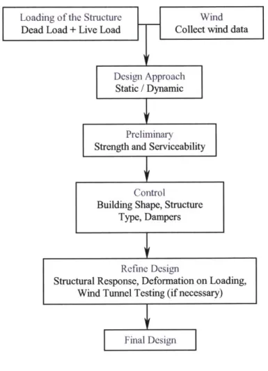
3.6. Design Procedures
The steps of the design procedures are discussed in the above section. Pulling together all the steps are the design procedure generally being taken and it is summarized in the following chart.
SLoading of the Structure
Wind Dead Load + Live Load ~~Collect wind data
Design Approach Static / Dynamic
Preliminary Strength and Serviceability
Control
Building Shape, Structure Type, Dampers
Refine Design
Structural Response, Deformation on Loading, Wind Tunnel Testing (if necessary)
Final Design
Figure 2 Design procedure
4. Control
Unlike the classical dynamic effects, for example, those of machines, the wind effects are known to possess no fixed frequency. Consequently, effective measures to control
wind-induced vibration are usually more difficult to accomplish in buildings than in machineries.
There are several simpler ways to reduce the effect of structural vibrations. A direct approach is to stiffen the structure by changing its mass, for example, by concreting in some of the elements. Another approach is to reduce the deflection of a building is through various structure types such as frame structures, tubular structures, and outrigger structures.
Now a day, as buildings reach for maximum possible heights, they become more flexible. Advances of base isolation also require the building to be softer. Increasing stiffness of a building is no longer the perfect solution to the deflection of buildings. This leads to remarkable developments in dampers. Dampers of various complexities will be
discussed further below.
The discussion of control strategies in the flowing will begin with the various types of structures as they are the most common practice. It is then followed by the highest potential control approach - dampers. Lastly, methods with less complexity such as
altering mass and aerodynamic shape will be discussed.
4.1. Types of Tall Building Structures
Tall building structures are generally divided into several categories such as frame structures, shear wall structures, tubular structures, outrigger structures, and the hybrid
structures. Each type of structure has its own advantages, and appropriate employment will lead to a structurally sound and aesthetically pleasing structure.
4.1.1. Braced Frame
Braced frames are cantilevered vertical trusses which resist lateral loads primarily through the axial stiffness of the frame members. For slender truss systems, axial shortening and elongation of the column members accounts for 80-90% of the overall system deformation [2]. Braced frames are known for their high ratio of stiffness to quantity of material, and are very effective for multistory buildings in the low- to mid height range. One advantage of bracing is that the horizontal loading does not contribute significantly to the girder forces, consequently, the size of the girders can remain constant over the height of the structure providing cost-cutting measure in design and
construction.
There are two main types of braced frames, concentric braced frames and eccentric braced frames. Concentric braced frames have high stiffness but low ductility, as all members intersect at a point such that the member forces are axial. In areas of low seismic activity, where high ductility is not essential, it is the most common way to achieve lateral load resistance. It takes the form of an X, Pratt, diagonal, K, or V. The X bracings possess higher lateral stiffness-to-weight ratios in comparison to K or V
bracings. However, the X bracings assume a portion of the column load in proportion to their stiffness. This creates additional forces in both diagonal and horizontal members of X-bracing systems, and it is needed to be addressed in the design. [2]
K Bracing Pratt Diagonal
Bracing Bracing
Figure 3 Concentric braced frame forms
X Bracing Knee
Bracing
V Bracing
Eccentric braced frames lower the stiffness-to-weight ratio it utilizes axis offsets to allow flexure and shear into the frame. To accommodate door and other openings, eccentric braced frames are commonly used. The shear and flexural action caused by the axis offset in the link beam improves ductility. Even higher ductility can be achieved through the elastic shear or bending action of the link beam, making it a desirable lateral systems in areas of high seismic activity. [2]
Braced frames are most commonly made from structural steel because of the ease of construction. Various shape such as double angles, channels, tees, tubes, or wide-flange may be used to make the diagonal frames, depending on the diagonal force, length, required stiffness, and clearances. Besides performance, the shape of the diagonal is
often chosen based on connection considerations. In addition, increasing the stiffness and strength of the chord members in proportion to the work done by those members is also efficient in minimizing sway. [6]
Vertical trusses are often located in the elevator and service core areas of high-rise buildings, where frame diagonals may be enclosed within permanent walls. Braced frames can be joined to form closed section cells, which act together effectively in resisting torsional forces. These cells are bundled for additional stiffness, as well as for systematic means of removing the cells at the upper levels of a tower where lateral forces are reduced. [2]
When slenderness ratio of a core truss increases, the overall overturning effect also increases leading to an increase in axial deformation and uplift forces of chord columns. Though truss chord members may readily be designed to resist tension forces, net
foundation uplift forces are nevertheless undesirable. One strategy is to spread the chords as far as possible to divert gravity load to these chords to reduce the net tensile force. [6]
Although bracing has been used typically in story-height bay width units, a recent development for very tall buildings has been to incorporate it in larger scale, multistory
multibay arrangements. This provides higher integral behaviour of the column-girder system in resisting both gravity and horizontal loading, thus creating highly efficient structural forms for very tall buildings. [6]
Figure 5 Braced Frame Parking Structure 121
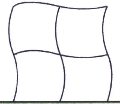
4.1.2. Moment Resisting Frame
A moment resisting frame consists of horizontal and vertical members rigidly connected together in a plane manner. Lateral load is resisted primarily based on the flexural stiffness of the member. The lateral deformation of the frame is due partly to the frame wracking, which is called shear sway, and partly to column shortening. Moment resisting frames have advantages in high-rise construction because of their flexibility in
architectural planning. A moment resisting frame may be placed in or around the core, on the exterior, or through out the interior of the building with minimal constraint on the planning unit.
Figure 6 Deformation of a moment Resisting Frame
For acceptable deflection control under lateral loads, the size of the members in a moment resisting frame is often controlled by stiffness rather than strength; and the lateral deflection is affected by both the column and beam stiffness. For sway control, moment resisting frame members increase in size and stiffness from top to bottom in proportion to the lateral shear.
Moment resisting frames are generally efficient for buildings around 20-30 stories in height. Member proportions and material costs become unreasonable for buildings higher than that. Due to the high cost of field assembly of moment connections, recent advances in moment resisting frames construction has been to produce the cross-shaped connections in shop and connect the center of the beams/columns together in field.
Connection between
pre-0 fabricated connections
* Moment Connection
4.1.3. Frame Truss Interacting System
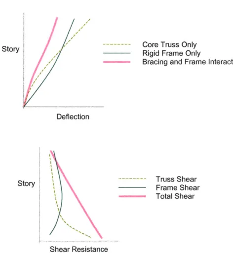
Frame truss interacting system is the combinations of shear trusses and moment resisting frames. This produces enhanced lateral stiffness. The truss is restrained by the frame at the upper part of the building, whereas at the lower part, the truss restrains the frame. As shown in figure 8, a truss system has less deflection and higher shear resistance than the frame system in lower stories, and vice versa. In general, core trusses are combined with moment frames located on the building perimeter. Optimum efficiency is obtained when gravity-designed columns are used as truss chords without increasing them for wind forces.
Story Core Truss OnlyRigid Frame Only
Bracing and Frame Interaction
Deflection
Story Truss Shear
Frame Shear Total Shear
Shear Resistance
4.1.4. Shear walls
Shear walls have been the most widely adopted structural systems in the past for
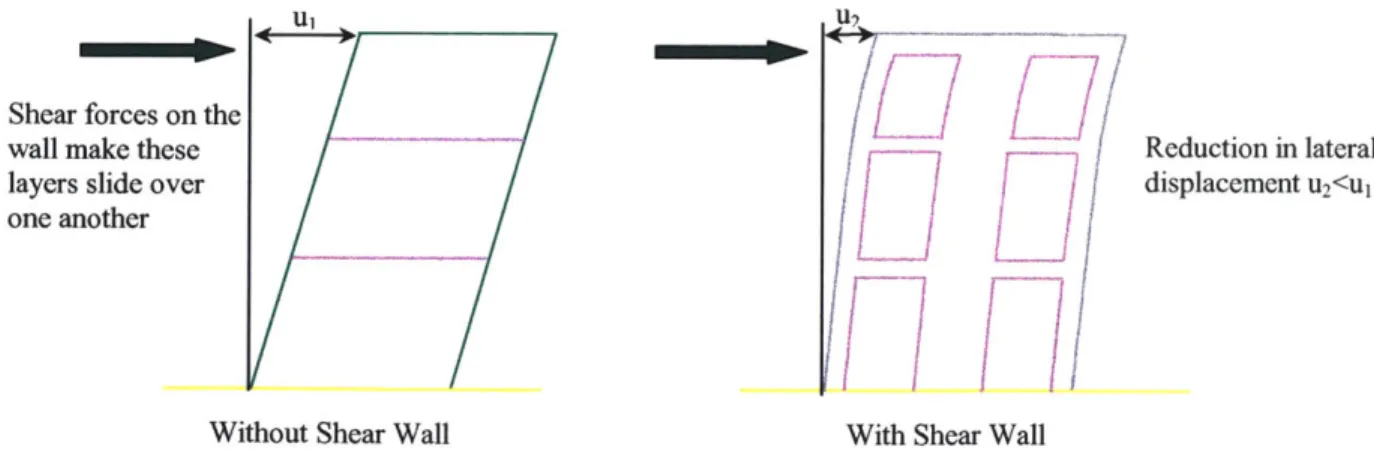
stabilizing building structures against horizontal forces caused by wind. With the advent of reinforced concrete, even the tallest building structures are efficiently controlled by shear wall systems. Most shear wall systems used for tall office buildings group shear walls around service cores, elevator shafts, and stairwells to form a stiff box structure. Multiple shear walls throughout a tall building may be coupled to provide additional frame action and to increase the overall building stiffness. By adding a coupling shear wall at a single level, reverse curvature is induced in the core above the coupling shear wall, and this significantly reduces lateral deflection. As the increase in mass is minimal, there will be an increase in the building's natural frequency. This can be a desirable effect, in particular with respect to achieving an acceptable wind-induced acceleration response to ensure occupant comfort. Central core boxes can also be coupled through stiff beams or trusses, at discrete levels, to external shear walls or columns to achieve a more distinct effect than that noted.
Shear forces on the
wall make these Reduction in lateral
layers slide over displacement u2<u1
one another
Without Shear Wall With Shear Wall
4.1.5. Tubular system
In order to satisfy architectural challenges, such as the elimination of interior walls to increase room for rent in office buildings, and structural performance, various types of tubular structure are developed. A discussion of the several most common systems follows here.
4.1.5.1. Frame tube system
Frame tube system is a logical extension of the moment resisting frame. It is generally composes one of closely spaced exterior columns and deep spandrel beams rigidly connected together. The entire assemblage continuous along each fagade and around the building corners to form a tube. Depending on the height and dimensions of the building, exterior column spacings should be on the order of 1.5m (4.5 ft) to 4.5m (13.5 ft) from center to center. The resulting arrangement approximates a tube cantilever. The closely spaced and deep exterior members often eliminate partially or totally the need for
intermediate vertical mullion elements of the curtain wall. However, the column spacing must be evaluated to balance between the needs for higher cantilever efficiency through closer spacings and increased fabrication costs. Besides, limited variety of fagade geometries, and the desire for open views may make a framed-tube structural solution undesirable. [2]
The more the structure is similar to a fully rigid box, cantilevered at the base, the more efficient the system will be. For the case of a solid-wall tube, the distribution of axial forces would be expected to be uniform over the windward and leeward walls and linear over the sidewalls. As the tubular walls are punched, creating the beam-column frame,
shear frame deformations are initiated due to shear and flexure in the tubular members as well as rotations of the member joints. This reduces the effective stiffness of the system as a cantilever. The extent to which the actual load distribution in the tube columns
deviates from the ideal is termed the "shear lag effect". To describe this behaviour, the forces in the columns toward the middle of the flange frames lag behind those nearer the corner and are thus less than fully utilized. Limiting the shear lag effect is essential for optimal development of the tubular system. A reasonable objective is to obtain at least 75% efficiency such that the cantilever component dominate the overall system
deflection under wind load. [2]
4.1.5.2. Truss Tube
For very tall buildings, the closely spaced beam and column members have an
undesirable impact on the faqade architecture. The only solution to control shear lag and improve the system efficiency is by making relatively small perforations in the tubular walls. The particular is heightened at the base of the building, where architectural planning typically demands open access to the building interior from the surrounding.
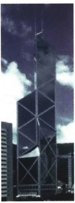
The trussed tube system represents a classic form of structure uniquely suitable for the qualities and characteristics of structural steel. The ideal tubular system is one which interconnects all exterior columns to form a rigid box, at the same time is able to resist lateral shears by axial forces in its members rather than through flexure. This is achieved by the application of a minimum number of diagonals on each faqade and making the diagonals intersect at the same point at the corner column. The system is tubular in that the diagonals not only form a truss in the plane but also interact with the trusses on the perpendicular faces to control the tubular behaviour.
A significant advantage of the trussed tube system is that relatively broad column spacings can be used in contrast to framed tube systems. The result is large clear spaces for windows, a particular characteristic of steel buildings.
To extend the concept of a trussed tubular system to reinforced concrete construction, a diagonal pattern of window perforations is filled in between adjacent columns and girders. This result in a reduction in shear lag for the system under wind loads. As for the steel framed trussed tube, an additional benefit associated with the system is that the fagade diagonalization serves to equalize the gravity loads in the exterior columns.
4.1.5.3. Bundled Tube
For buildings with varying profiles and buildings involving significant vertical fagade offsets, serious inefficiencies arise from the discontinuity of the tubular frame to fit the shape. However, the system can be readily modified into a variety of non-rectangular, closed plan forms, including circular, hexagonal, triangular, and other polygonal shapes. The most efficient shape is the square, whereas the triangular tube has the least inherent efficiency. The high torsional stiffness characteristic of the exterior tubular system has advantages in constructing unsymmetrical shapes. Researchers have indicated that if the tube size is made smaller in relation to its height a higher aspect ratio is obtained. This leads to the bundled tube concept in which the overall tubular shape is structured into small cells by the inclusion of interior tubular lines. The overall structure has the cantilever efficiency computed as the ratio of the actual top deflection to the top deflection of a full cantilever without shear lag. [2]
The bundled tube concept allows for wider column spacings in the tubular walls than would be possible with only the exterior framed tube form. It is this spacing which makes it possible to place interior frame lines without seriously involving interior space planning. This innovative structural concept achieves an efficient, simple to erect structure utilizing a perimeter tube whose behaviour closely approximates a pure cantilever. [2]
Figure 12 Sears Tower
4.1.6. Outrigger structures
Outriggers serve to reduce the overturning moment in the core by transferring the reduced moment to columns along the perimeter by a tension-compression couple. The effective moment increases as the distance between the core and the columns increases. In addition to reducing the size of the core, the presence of the outriggers also serves to reduce the critical connection where the core is linked to the beam. It has the advantage of reducing base core overturning moments and the potential core uplift forces
Modem high-rise buildings usually incorporate central elevator cores along with generous column-free floor space between the core and the exterior support columns. This uncouples the interior core with the exterior column and reduces the overall resistance of the structure to the overturning forces. Reinforced concrete shear wall or steel braced cores have been effectively utilized as the sole lateral load resisting system. These systems are very effective in resisting the forces and associated deformations due to shear cracking since their resistance varies approximately with the buildings height. However, the resistance that core systems alone provide to reduce the overturning
component of deflection decreases approximately with the cube of the height. These core systems become progressively more inefficient as the height of the building increases. The incorporation of outriggers in such system will couple these two components and enhance the system's ability to resist overturning forces dramatically. [2]
The benefits of outriggers are numerous. Outrigger systems may be formed in any combination of steel, concrete, or composite construction. Core overturning moments and their associated induced deformation can be reduced through the reverse moment applied to the core at each outrigger intersection. This moment is created by the force couple in the exterior columns connecting to the outriggers. Significant reduction and complete elimination of uplift and net tension forces throughout the columns and foundation
system are possible. The exterior column spacing is not driven by structural considerations and can easily conformed to various aesthetic and functional considerations. [2]
Exterior frame can consist of "simple" beam and column framing without the need for rigid-frame-type connections, resulting in reduction of construction costs. For
rectangular buildings, outriggers can couple the core with the long faces or the more critical direction of the building. In core-alone and tubular systems, these columns which carry significant gravity load are either not incorporated or underutilized. The system is flexible and is particularly applicable to cases where there are limits on the structural size of the beam and columns by architecture.
4.1.7. Hybrid Systems
The advent of economical, easy-to-use, high capacity computer hardware and software, has made mixed structural system more realistic and simpler. This allows the designer to incorporate the benefit of different structural system and accommodate the need of the
4.2. Passive control
Passive control systems have been widely used for reducing wind effects on tall buildings because of the relative simplicity and low cost. Advantages and effectiveness have been ascertained through numerous successful application. Directional mass dampers, along the wind direction and cross the wind direction, are widely used as well as visco-elastic dampers.
There has been considerable amount of research done on how to best design the mass dampers for use in passive damping of tall and flexible structures under excitation forces such as wind and earthquake. It is well know that a passive mass damper system is most effective when the frequency of the mass damper is tuned to the frequency of the
structure.
Various typical dampers are discussed in the follow sections.
4.2.1. Tuned Mass Damper
Tuned Mass Damper, TMD, is a passive control system composed of a mass which oscillates at the same period as the building does and an additional damper that connects two relatively moving points when the building oscillates. It absorbs the vibrations automatically without the need of an electrical control system. TMDs are very effective in suppressing the oscillation of a building caused by high winds.
To~p fkk of building
WindJR4 L
Figure 14 Location of tuned mass damper
The frequency of the damper is tuned to a particular structural frequency so that when that frequency is excited, the damper will resonate 90* out of phase with the structural motion. Energy is dissipated by the damper inertia force acting on the structure. Various cases including an undamped TMD attached to an undamped Multi-Degree of Freedom (MDOF) system, a damped TMD attached to an undamped MDOF system, and a damped TMD attached to a damped MDOF system are employed in practice. [1]
With an addition of about 2% of the primary mass, one obtains an effective damping ratio of 10%. The negative aspect is the large relative motion of the damper mass; it may be as large as 10 times the displacement of the primary mass. The means to accommodate this motion in an actual structure is an important design consideration. [1]
4.2.1.1. Translational tuned mass damper
The way how translational tuned mass damper works is suggested by its name. The damper translates horizontally with respect to the floor and produces an "out-of-phase"
force to the floor, which transfers the force into the structural frame. Bi-directional translational dampers are configured with springs/dampers in 2 orthogonal directions and provide the capability for controlling structural motion both along and crosswind
direction.
Figure 15 Translational Tuned Mass Damper for Chiba Port Tower [1
4.2.1.2. Pendulum tuned mass damper
Pendulum tuned mass damper solves the bearing problems by connecting the supporting the mass with cables. This allows the system to behave as a pendulum. Movement of the floor excites the pendulum and the relative motion of the pendulum produces a horizontal force which oppose the floor motion.
This TMD utilizes a crystal ice heat storage tank installed for air conditioning on the roof as a mass for controlling building movement. Small size TMD with a large capacity could be realized.
Figure 16 Crystal Building - Modified Pendulum Tuned Mass Damper [81
The fundamental advantage of this TMD is the ability to reduce the required floor space due to "stacking"
The mass is located at the center of a multi-stage frame (3). The stages are connected to each other by ropes (2), which provide a natural period control adjustment (4). Only the outermost frame is fixed to the building floor. The controlled driving device, located at the bottom of the system, is comprised of AC servo motors (5), ball screws (6), X-Y beams (7) and a universal joint (8) connecting the driving device to the mass (1).
Figure 17 Multi-Step Tuned Mass Damper [81
4.2.2. Water tank/Artificial Lakes damper
In a tower building in Australia, the mass of the damper is provided by a large tank of water. The natural frequencies of the free surface waves in the tank were theoretically derived and the results were applied to a model. Their behaviour is similar to a tuned