Publisher’s version / Version de l'éditeur:
Vous avez des questions? Nous pouvons vous aider. Pour communiquer directement avec un auteur, consultez la première page de la revue dans laquelle son article a été publié afin de trouver ses coordonnées. Si vous n’arrivez pas à les repérer, communiquez avec nous à [email protected].
Questions? Contact the NRC Publications Archive team at
[email protected]. If you wish to email the authors directly, please see the first page of the publication for their contact information.
https://publications-cnrc.canada.ca/fra/droits
L’accès à ce site Web et l’utilisation de son contenu sont assujettis aux conditions présentées dans le site
LISEZ CES CONDITIONS ATTENTIVEMENT AVANT D’UTILISER CE SITE WEB.
First AO4ELT conference - Adaptive Optics for Extremely Large Telescopes, pp.
1-6, 2010-02-24
READ THESE TERMS AND CONDITIONS CAREFULLY BEFORE USING THIS WEBSITE.
https://nrc-publications.canada.ca/eng/copyright
NRC Publications Archive Record / Notice des Archives des publications du CNRC :
https://nrc-publications.canada.ca/eng/view/object/?id=eaa5ef23-6011-409b-ac39-cb46f0ff8f3f
https://publications-cnrc.canada.ca/fra/voir/objet/?id=eaa5ef23-6011-409b-ac39-cb46f0ff8f3f
NRC Publications Archive
Archives des publications du CNRC
This publication could be one of several versions: author’s original, accepted manuscript or the publisher’s version. / La version de cette publication peut être l’une des suivantes : la version prépublication de l’auteur, la version acceptée du manuscrit ou la version de l’éditeur.
For the publisher’s version, please access the DOI link below./ Pour consulter la version de l’éditeur, utilisez le lien DOI ci-dessous.
https://doi.org/10.1051/ao4elt/201005012
Access and use of this website and the material on it are subject to the Terms and Conditions set forth at
The TMT/NFIRAOS LGS wavefront sensing demonstration bench
Conan, R.; Lardière, O.; Herriot, G.; Bradley, C.; Jackson, K.
The TMT/NFIRAOS LGS wavefront sensing demonstration
bench
R.Conan1,a, O. Lardi`ere1, G. Herriot2, C. Bradley1, and K. Jackson1 1 Adaptive Optics Laboratory, University of Victoria
2 NRC-Herzberg Institute of Astrophysics, Victoria, Canada
Abstract. LGS wavefront sensing on ELTs is challenging. The tip-tilt indetermination, the cone effect, the star elongation, the sodium profiles fluctuations are the main problems plaguing LGS wavefront sensors. The AO Laboratory at the University of Victoria has build a LGS wavefront sensing test bed scaled for the TMT, reproducing the sodium variations and the whole NFIRAOS wavefront sensing scheme. The details of the bench design are given and the implementation of the wavefront sensing algorithm is presented. This one includes a matched filter, zoom optics control, DM command and truth wavefront sensors management.
1 Introduction
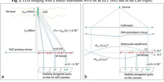
Both next largest optical telescopes, the TMT and the E–ELT, will equipped their AO systems with Laser Guide Stars (LGS). When seen through a SH–WFS conjugated to the primary mirror of an ELT, the spot elongation away from the LGS launch axis is large enough to resolve the fluctuations in the Na layer profiles.
Fig. 1 (a) shows the imaging process of a LGS with a Shack–Hartmann WFS. The thickness of the Na layer induces a LGS spanning the whole layer. The lenslets of the SH–WFS on the side of the telescope primary mirror are imaging the LGS sideways producing an elongated spot. The elongated spot intensity is proportional to the Na density profile in the Na layer. The Na profile is varying with time hence affecting the centroid of the elongated spot of an non–optical error. The temporal controller of a closed–loop AO system will perceive this error as an optical error attempting to correct for it with the DM adding new optical aberration in the science path.
New centroiding schemes have been derived to overcome the LGS induced aberrations problem. Most of these algorithms have been tested with end–to–end simulation. In this paper, an optical test bed is presented which reproduces the features of a LGS guide star as seen from a SH–WFS at an ELT.
2 The Bench
The Adaptive Optics Laboratory of the University of Victoria has built an optical test bench[6] ded-icated to LGS wavefront sensing. This bench is tailored to NFIRAOS[5], the TMT[2] AO facility. It has the following features:
– spot elongation of 4” (8 pixels)
– dynamic zoom to focus on mean Na layer altitude – sodium density variations (spatial & temporal) – dithering of the spots for the matched filter – able to generate some atmospheric turbulence – combine both LGS and NGS WFSs
Fig. 2 is a picture of the bench layout with the two WFSs, the DM and the two sources. The LGS WFS has 29×29 lenslets with 15×15 pixels for each. The NGS WFS has 12×12 lenslets with 8×8
a e-mail: [email protected]
AO for ELT
Fig. 1. LGS imaging with a Shack–Hartmann WFS on an ELT (left) and in the Lab (right).
Fig. 2. The UVic AO Lab LGS wavefront sensing test bench.
pixels for each. The DM is a magnetic ALPAO DM with 88 actuators in the pupil on a 10×10 regular grid. The two sources are point like Laser diode at 600nm and 700nm.
Fig. 1(b) describes the process to make elongated spot on the test bench. To create the spot elonga-tion, a focus mode is applied to the DM. The amplitude of the focus alternates between two min/max values. Consequently, the point like spots sweep the detector while the electronic shutter remains open during the sweeping. After running an entire range a focus, the camera is read out giving the elongated spots. The elongation size depends on the distance of the lenslet from the optical axis. Fig. 3 shows spot images produced with the bench. On the left, it is an image for a LGS launch on–axis from a 30m telescope and a 20km thick Na layer. On the right, it is an image for a side launch Laser and a 7.5km thick Na layer on a 42m telescope.
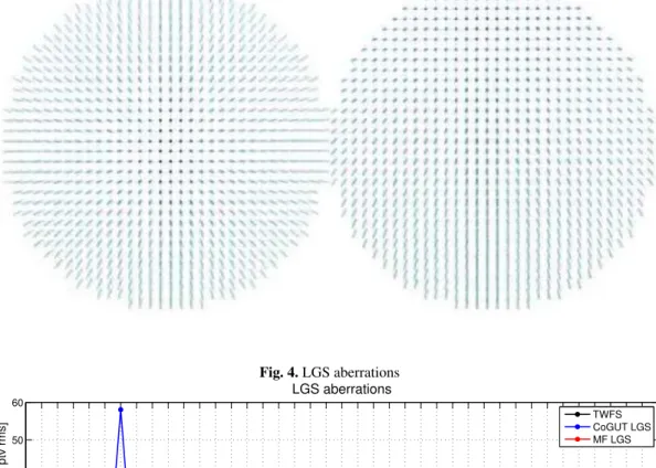
Using Na profiles from UBC Lidar, the performance of different centroiding algorithms has been compared. Fig. 4 shows the rms of ptv Zernike modes for a center–of–gravity (CoG) and a matched filter (MF)[4, 1]. These errors are obtained by reproducing a time sequence of Na profiles and project-ing the slopes deduced from both algorithms onto the Zernike polynomials. It demonstrates how the MF mitigates the LGS aberrations.
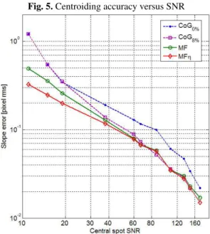
Fig. 5 shows the centroiding error as a function of the SNR measured on an non–elongated spot. It compares non–thresholded (CoG0%) and thresholded (CoG8%) CoG algorithms to a standart MF and a noise–weighted MF[3] (MFη). The noise–weighted MF gives the smallest error especially at low SNR. It means too that for a given error when using MFη, one can work at a lower SNR than the CoG allowing to save, for example, costly Laser power.
First conference on Adaptive Optics for Extremely Large Telescopes
Fig. 3. Central(left) and side(right) launch LGS reproduced with the bench. Fig. 4. LGS aberrations 5 6 7 8 9 10 11 12 13 14 15 16 17 18 19 20 21 22 23 24 25 26 27 28 29 30 31 32 33 34 35 36 37 38 39 40 41 42 43 44 45 0 10 20 30 40 50 60 LGS aberrations Zernike modes WF standart deviation [nm ptv rms] TWFS CoGUT LGS MF LGS
3 NFIRAOS LGS wavefront sensing control system
The LGS wavefront sensing bench has been used to implement and to validate the whole NFIRAOS LGS/NGS wavefront sensing control system. Fig. 6 shows the complete control system. Apart the LGS WFS, two NGS WFS are used. The on–instrument tip–tilt-focus WFS (OI TTF WFS) is a fast SH–WFS measuring only tip–tilt and focus modes. The medium order WFS (MOR WFS) is a slow WFS measuring low order modes above focus. A fast steering mirror (FSM) is used to stabilize and to dither the Laser. A zoom optics re-focus the light to infinity. And the DM off–course corrects the phase aberrations.
On the bench, a single 12×12 NGS WFS is used to emulate both OI TTF WFS and MOR WFS. The NGS WFS is run as fast as the LGS WFS. The slopes are projected onto Zernike modes. The Zernike modes above the focus are time averaged to reproduce the slow MOR WFS measurements. The FSM and DM are both emulated with a single ALPAO DM. The zoom optics is reproduced by numerically shifting the barycenter of the Na profiles.
AO for ELT
Fig. 5. Centroiding accuracy versus SNR
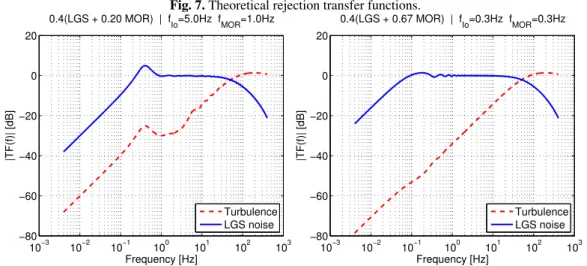
The rejection transfer functions of the system have been derived analytically. Fig. 7 shows the rejection transfer functions of the turbulence and of the LGS aberrations. As the data of the LGS WFS and of the MOR WFS are blended together, the update rate fIOof the MF reference image and gain
and the frame rate fMORof the MOR WFS have to be chosen carefully.
The MOR and LGS WFS data are added together the following way gI(LGS + gMORMOR). gI is
the gain of the DM integrator and gMORis the gain of the MOR WFS. gMORwill affect the settle time
and the stability of the closed loop system.
In Fig. 7, it can be seen that when fIO= fMOR, the DM/LGS+MOR system behaves like a DM and
single WFS system. If the MOR WFS frame rate is too slow with respect to the MF update rate, low frequency aberrations are under–corrected. The mathematical model has been checked against bench results. Fig. 8 shows bench measured rejection transfer functions for the two same cases plotted in Fig. 7. It confirms that when both frequencies are the same, the system acts like a one WFS closed loop AO system. Whereas with a slower MOR WFS, the low frequency correction is poorer.
4 Conclusion
The Adaptive Optics Laboratory of the University of Victoria has built a optical test bed for LGS wavefront sensing. The bench reproduces the spot elongation and the Na layer fluctuation. For NFI-RAOS, the TMT AO facility, the center–of–gravity and matched filter centroiding algorithms ability to mitigate LGS aberrations have been compared. It has been shown that the MF is able to track the LGS aberrations while correcting for the turbulence. In addition, for a given wavefront error the MF can work at a lower SNR than the CoG.
The whole DM/NGS+LGS closed–loop control system of NFIRAOS has also been implemented on the bench. It has allowed to validate and to improve the different algorithms and control design choices. It has been shown that the best performance are obtained when the update rate of the MF and the frame rate of the MOR WFS are the same. The gains of the control system can be optimized based on the analysis of the transfer functions of the system computed from an analytical model of NFIRAOS control system. The model has been found to be in good agreement with the transfer functions measured with the bench.
A new LGS WFS tailored to the E–ELT specifications is going to be integrated into the bench. It will allow to compare how centroiding algorithms like CoG, MF, quad–cell, weighted CoG and correlation mitigate the LGS aberrations for central and side launch Laser.
First conference on Adaptive Optics for Extremely Large Telescopes
R.Conan et al.: The TMT /NFIRA OS LGS w av efront sensing demonstration bench gLF Dither + − R ++ DLL Slopes to Modes Amplitude Estimator Synch. Detector ZOH TT rig LPF(α) Matched Filter MF Slopes Laser FSM LPF(α′ ) LGS DM − + Zoom Optics LGS WFS Ts R Tib Tib ZOH Centroids NGS R TZO Slopes to Drift Modes NGS R OI TTF WFS TT T F Slopes to Modes + − MOR WFS TMOR Slopes to Modes>4 LPF + + + − gMOR + + Merge ik ib i0 G R cdit fFS M eFS M dFS M Aest NCP LGS I0tip-tilt: t0 LGS MF tip-tilt: t LGS I0focus LGS MF focus: fLGS LGS MF high order: zLGS fT T F tip–tilt 05012-p.5
AO for ELT
Fig. 7. Theoretical rejection transfer functions.
10−3 10−2 10−1 100 101 102 103 −80 −60 −40 −20 0 20 Frequency [Hz] |TF(f)| [dB] 0.4(LGS + 0.20 MOR) | f Io=5.0Hz fMOR=1.0Hz Turbulence LGS noise 10−3 10−2 10−1 100 101 102 103 −80 −60 −40 −20 0 20 Frequency [Hz] |TF(f)| [dB] 0.4(LGS + 0.67 MOR) | f Io=0.3Hz fMOR=0.3Hz Turbulence LGS noise
Fig. 8. Bench measured rejection transfer functions.
It is worth noting too that the bench can work as an analogical computer for LGS–based tomo-graphic AO. The WFS measurements in different directions can be taken serially and combine after-wards together to reconstruct the turbulence layers. It would be able to take into account the anisopla-naticity of the turbulence and of the Na layer. It could include NGS and LGS WFSs of different orders and with different SNRs.
References
1. Rodolphe Conan, Olivier Lardi`ere, Glen Herriot, Colin Bradley, and Kate Jackson. Appl. Opt., 48(6):1198–1211, 2009.
2. B. Ellerbroek, S. Adkins, D. Andersen, J. Atwood, C. Boyer, P. Byrnes, R. Conan, L. Gilles, G. Her-riot, P. Hickson, E. Hileman, D. Joyce, B. Leckie, M. Liang, T. Pfrommer, J.-C. Sinquin, J.-P. Veran, L. Wang, and P. Welle. volume 7015, Proc. SPIE, July 2008.
3. L. Gilles and B. L. Ellerbroek. Opt. Lett., 33(10):1159–1161, 2008. 4. Luc Gilles and Brent Ellerbroek. Appl. Opt., 45(25):6568–6576, 2006.
5. G. Herriot, P. Hickson, and B. Ellerbroek et al. In Advances in Adaptive Optics II, volume 6272. Proc. SPIE, June 2006.
6. Olivier Lardiere, Rodolphe Conan, Colin Bradley, Kate Jackson, and Glen Herriot. Opt. Express, 16(8):5527–5543, 2008.
First conference on Adaptive Optics for Extremely Large Telescopes