Autonomous Flight in Unknown Indoor Environments
The MIT Faculty has made this article openly available. Please share
how this access benefits you. Your story matters.
Citation
Bachrach, Abraham, Ruijie He, and Nicholas Roy. “Autonomous
Flight in Unknown Indoor Environments.” International
Journal of Micro Air Vehicles 1 (2009): 217-228. DOI:
10.1260/175682909790291492
As Published
http://dx.doi.org/10.1260/175682909790291492
Publisher
Multi-Science Publishing
Version
Author's final manuscript
Citable link
http://hdl.handle.net/1721.1/66162
Terms of Use
Creative Commons Attribution-Noncommercial-Share Alike 3.0
Autonomous Flight in Unknown Indoor Environments
Abraham Bachrach, Ruijie He and Nicholas Roy∗Massachusetts Institute of Technology, Cambridge, MA, USA
ABSTRACT
This paper presents our solution for enabling
a quadrotor helicopter, equipped with a laser rangefinder sensor, to autonomously explore and map unstructured and unknown indoor environ-ments. While these capabilities are already com-modities on ground vehicles, air vehicles seeking the same performance face unique challenges. In this paper, we describe the difficulties in achiev-ing fully autonomous helicopter flight, highlight-ing the differences between ground and heli-copter robots that make it difficult to use al-gorithms that have been developed for ground robots. We then provide an overview of our so-lution to the key problems, including a multi-level sensing and control hierarchy, a high-speed laser scan-matching algorithm, an EKF for data fusion, a high-level SLAM implementation, and an exploration planner.1 Finally, we show ex-perimental results demonstrating the helicopter’s ability to navigate accurately and autonomously in unknown environments.
1 INTRODUCTION
Micro Aerial Vehicles (MAVs) are increasingly being used in military and civilian domains, including surveillance operations, weather observation, and disaster relief coordina-tion. Enabled by GPS and MEMS inertial sensors, MAVs that can fly in outdoor environments without human intervention have been developed [2, 3, 4, 5].
Unfortunately, most indoor environments and many parts of the urban canyon remain without access to external posi-tioning systems such as GPS. Autonomous MAVs today are thus limited in their ability to fly through these areas. Tra-ditionally, unmanned vehicles operating in GPS-denied en-vironments can rely on dead reckoning for localization, but these measurements drift over time. Alternatively, simul-taneous localization and mapping (SLAM) algorithms build a map of the environment around the vehicle while simul-taneously using it to estimate the vehicle’s position. Al-though there have been significant advances in developing accurate, drift-free SLAM algorithms for large-scale envi-ronments, these algorithms have focused almost exclusively on ground or underwater vehicles. In contrast, attempts to
∗Email addresses:{abachrac, ruijie, nickroy}@mit.edu
1The system described in this paper was originally presented for the 2009
European Micro Air Vehicle Conference [1]
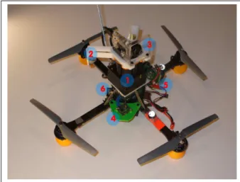
Figure 1: Our quadrotor helicopter. Sensing and computation components include a Hokuyo Laser Rangefinder (1), laser-deflecting mirrors for altitude (2), a monocular camera (3), an IMU (4), a Gumstix processor (5), and the helicopter’s internal processor (6)
achieve the same results with MAVs have not been as suc-cessful due to a combination of limited payloads for sensing and computation, coupled with the fast, unstable dynamics of the air vehicles.
In this work, we present our quadrotor helicopter system, shown in Figure 1, that is capable of autonomous flight in unstructured indoor environments, such as the one shown in Figure 2. The system employs a multi-level sensor process-ing hierarchy designed to meet the requirements for control-ling a helicopter. The key contribution of this paper is the development of a fully autonomous quadrotor that relies only on onboard sensors for stable control without requiring prior maps of the environment.
After discussing related work in Section 2, we begin in Section 3 by analyzing the key challenges MAVs face when attempting to perform SLAM. We then give an overview of the algorithms employed by our system. Finally, we demon-strate our helicopter navigating autonomously in 3 different unstructured indoor environments.
2 RELATEDWORK
In recent years, autonomous flying robots has been an area of increasing research interest. Many capabilities have been developed for autonomous operations in outdoor ronments, including high-speed flight through cluttered envi-ronments [3], helicopter acrobatics [4], autonomous landing
Figure 2: Autonomous flight in unstructured indoor environ-ments
and terrain mapping [5], coordinated tracking and planning of ground vehicles [2], etc. These systems typically take ad-vantage of GPS measurements for state estimation, which are not available indoors.
While some authors [6, 7] have demonstrated indoor flight using GPS simulated from motion capture systems, we seek to develop flying robots that are able to operate au-tonomously while carrying all sensors used for localization, control and navigation onboard. Other authors [8, 9] use a small number of ultrasound sensors to perform altitude con-trol and obstacle avoidance. Their helicopters are able to take-off, land and hover autonomously; however, they do not achieve goal-directed flight.
There have been numerous efforts to fly helicopters au-tonomously indoors using monocular camera sensors. [10] performed visual servoing over known Moire patterns to ex-tract the full 6 degree-of-freedom state of the vehicle for con-trol, while [11] detects lines in a hallway, and [12] tracked edges in office environments with known structure. While these authors have demonstrated autonomous flight in limited indoor environments, their approaches have been constrained to environments with specific features, and thus may not work as well for general navigation in GPS-denied environments. [13] extracted corner features that are fed into an EKF-based Vision-SLAM framework, building a low-resolution 3D map sufficient for localization and planning. However, an external motion capture system was used to simulate inertial sensor readings.
This paper builds on our previous work in [14], where we presented a planning algorithm for a laser-equipped quadrotor helicopter that is able to navigate autonomously indoors with a given map. Here, we extend the work by developing a sys-tem that is able to navigate, localize, build maps and explore autonomously without a prior map.
Recently, [15, 16] designed helicopter configurations that were similar to the one presented in [14]. [15] scan-matched successive laser scans to hover their quadrotor helicopter,
their helicopter with a precomputed map that was generated by a ground-based robot. However, none of these papers present experimental results demonstrating the ability to sta-bilize all 6 dof of the helicopter autonomously using the on-board sensors.
3 MAV-SPECIFICCHALLENGES
In the ground robotics domain, combining wheel odom-etry with sensors such as laser rangefinders, sonars, or cam-eras in a probabilistic SLAM framework has proven very suc-cessful [17]. Many algorithms exist that accurately localize ground robots in large-scale environments. Unfortunately, the process of mounting equivalent sensors onto a helicopter and using existing SLAM algorithms does not result in the same success. The requirements and assumptions that can be made with flying robots are sufficiently different from those that can be made with ground robots that they must be managed differently.
3.1 Payload
MAVs have a maximum amount of vertical thrust that they can generate to remain airborne, which severely limits the amount of payload available for sensing and computation compared to similar sized ground vehicles. This weight lim-itation eliminates popular sensors such as SICK laser scan-ners, large-aperture cameras and high-fidelity IMUs. Instead, indoor air robots rely on lightweight Hokuyo laser scanners, micro cameras and/or lower-quality MEMS-based IMUs, all of which have limited ranges and fields-of-view and are nois-ier compared to their ground equivalents.
Unlike ground vehicles, air vehicles are unable to mea-sure odometry directly; most SLAM algorithms need these measurements to initialize the estimates of the vehicle’s mo-tion between time steps. Although one can obtain relative position estimates by double-integrating acceleration mea-surements, lightweight MEMS-based IMUs are often sub-ject to errors that introduce a bias that drifts very quickly. We must therefore obtain relative position estimates measure-ments by using either visual odometry [18] or laser scan-matching [19, 20] algorithms.
Finally, despite the advances within the community, SLAM algorithms continue to be computationally demanding even for powerful desktop computers, and are therefore not implementable on today’s small embedded computer systems that can be mounted onboard indoor MAVs. The computa-tion can be offloaded to a powerful groundstacomputa-tion by trans-mitting the sensor data wirelessly; however, communication bandwidth then becomes a bottleneck that constrains sensor options. Camera data must be compressed with lossy algo-rithms before it can be transmitted over WiFi links, which adds noise and delay to the measurements. This noise partic-ularly affects feature detectors which look for high frequency information such as corners in an image. Additionally, while the delay can often be ignored for slow-moving,
passively-namics, making control under large sensor delay conditions impossible.
3.2 Dynamics
The helicopter’s fast dynamics result in a host of sens-ing, estimation, control and planning implications for the ve-hicle. Filtering techniques such as Kalman Filters are often used to obtain better estimates of the true vehicle state from noisy measurements. Smoothing the data generates a cleaner signal, but adds delay to the state estimates. While delays generally have insignificant effects on vehicles with slow dy-namics, the effects are amplified by the MAV’s fast dynamics. In addition, as will be discussed in Section 4, the quadro-tor is well-modeled as a simple 2nd-order dynamic system with no damping. The underdamped nature of the dynamics model implies that simple proportional control techniques are insufficient to stabilize the vehicle, since any delay in the sys-tem will result in unstable oscillations. This effect has been observed experimentally. We must therefore add damping to the system through the feedback controller, which empha-sizes the importance of obtaining accurate and timely state estimates for both position and velocity. Traditionally, most SLAM algorithms for ground robots completely ignore the velocity states.
Unlike ground vehicles, a MAV cannot simply stop and re-evaluate when its state estimates have large uncertainties. Instead, the vehicle is likely to be unable to estimate its ve-locity accurately, and may instead pick up speed or oscillate, degrading the sensor measurements further. Therefore, plan-ning algorithms for air vehicles must not only be biased to-wards paths with smooth motions, but must also explicitly reason about uncertainty in path planning, as demonstrated in [14]; motivating our exploration strategy in Section 5.4.
3.3 3D effects
Finally, MAVs operate in a truly 3D environment since they can hover at different heights. The visible 2D slice of a 3D environment can change drastically with height and at-titude, as obstacles suddenly appear or disappear. However, if we treat map changes resulting from changes in height and attitude as sensor errors, allowing the map to be updated to account for these changes, we will see that a 2D representa-tion of the environment is surprisingly useful for MAV flight.
4 SYSTEMOVERVIEW
We addressed the problem of autonomous indoor flight as primarily a software challenge, focusing on algorithms rather than exotic hardware. To that end, we used off-the-shelf hardware throughout the system. Our quadrotor helicopter, shown in Figure 1, is the AscTec Hummingbird from Ascend-ing Technologies GmBH2, and is able to carry roughly250g of payload. We outfitted it with a Gumstix3microcomputer, which provides a WiFi link between the vehicle and a ground
2Ascending Technologies GmBH.http://www.asctec.de 3Gumstix Verdex.http://www.gumstix.com
control station, and a lightweight Hokuyo4laser rangefinder for localization. The laser rangefinder provides a270◦ field-of-view at40Hz, up to an effective range of 30m. We deflect
some of the laser beams downwards to estimate height above the ground plane.
The AscTec Hummingbird helicopter is equipped with at-titude stabilization, using an onboard IMU and processor to stabilize the helicopter’s pitch and roll [21]. This tames the nastiest portions of the quadrotor’s extremely fast, nonlinear, and unstable dynamics [7], allowing us to focus on stabiliz-ing the remainstabiliz-ing degrees of freedom in position and headstabiliz-ing. The onboard controller takes 4 inputs, u = [uφ, uψ, ut, uθ], which denote the desired pitch and roll angles, overall thrust and yaw velocities respectively. The onboard controller al-lows the helicopter’s dynamics to be approximated with sim-ple2nd-order linear equations:
¨
xb= kφuφ+ bφ z = k¨ tut+ bt
¨
yb= kψuψ+ bψ ˙θ = kθuθ+ bθ (1)
wherex¨bandy¨bare the resultant accelerations in body coor-dinates, whilek∗andb∗ are model parameters that are func-tions of the underlying physical system. We learn these pa-rameters by flying the helicopter inside a Vicon5motion cap-ture system and fitting parameters to the data using a least-squares optimization method. We also experimented with a dynamics model that includes damping terms,
¨
s = k1u + k2˙s + b (2)
However, when fitting this model to the data, we found that
k2 ≈ 0, confirming pilot experience that the system is
un-derdamped. Using the Matlab R linear quadratic regulator
(LQR) toolbox, we then find feedback controller gains for the dynamics model in Equation 1.
To compute the high-precision, low-delay state estimates needed to stabilize the vehicle, we designed the 3-level sens-ing and control hierarchy, shown in Figure 3, distsens-inguishsens-ing processes based on the real-time requirements of their respec-tive outputs. This system was designed as a combination of asynchronous modules, building upon the CARMEN6robot navigation toolkit’s software architecture. We describe the individual modules in the next section.
5 ENABLINGTECHNOLOGIES
5.1 Laser Scan-Matching Algorithm
As discussed in Section 3.1, we cannot directly measure the MAV’s relative position. Instead, we align consecutive scans from the laser rangefinder to estimate the vehicle’s mo-tion using a standard technique from robotics known as scan-matching [22]. The goal of scan-scan-matching is to find the most
4Hokuyo UTM-30LX Laser.http://www.hokuyo-aut.jp 5Vicon Motion Capture Systems.http://www.vicon.com 6CARMEN.http://carmen.sourceforge.net
Figure 3: Schematic of our hierarchical sensing, control and planning system. At the base level, the onboard IMU and controller (green) create a tight feedback loop to stabilize the vehicle’s pitch and roll. The yellow modules make up the real-time sensing and control loop that stabilize the vehicle’s pose at the local level and avoids obstacles. Finally, the red modules provide the high-level mapping and planning func-tionalities.
likely alignment between pairs of laser scans, subject to the assumption that the same laser points are generated from the same physical object in the environment from time-step to time-step. Any deviation in the estimated range along the same bearing is assumed to be sensor noise. An additional constraint is that the alignment operator is a rigid body trans-formation on one of the scans, which corresponds to a rigid body transformation on the center of body of the vehicle. As a result, searching for the most likely alignment of laser scans corresponds to searching for the most likely motion of the ve-hicle between scans.
Scan-matching assumes that all range measurements are taken independently, which allows the likelihood of an align-ment to be computed as the product of likelihoods for each individual point in the scan. There are a number of possible models of measurement likelihood. In our implementation, we follow Olson et al’s model [20] of measurement likeli-hood of subsequent scans as a generative probabilistic model given by a Gaussian blur of a polygonal reduction of previ-ous scans. That is, a representation of the previprevi-ous scan is constructed as a set of piece-wise linear contours{C}, and
the probability of a single lidar point(x, y) is approximated
as proportional to the distance,d, to the nearest contour Ci, such that
P (x, y|Ci) ∝ e(−d/σ)
whereσ is a variance parameter that accounts for the sensor’s
noise characteristics.
Given the likelihood model from a previous scan, scan-matching proceeds by searching for the rigid transform
(x, y, θ) for a subsequent scan. Many scan-matching
algo-rithms use gradient descent techniques to optimize these
val-very complicated, even for fairly simple environments, gradi-ent descgradi-ent is subject to local optima. We instead use a very robust, if potentially computationally inefficient, exhaustive search over a grid of possible poses. While this exhaustive search might initially seem hopelessly inefficient, if imple-mented carefully, it can be performed fast enough to run in realtime. In our implementation, we use a grid spacing of
7.5mm in x, y, and .15◦inθ. At this resolution, it takes ap-proximately 5ms to search over the approximately 15, 000
candidate poses in the search grid to find the best pose for an incoming scan.
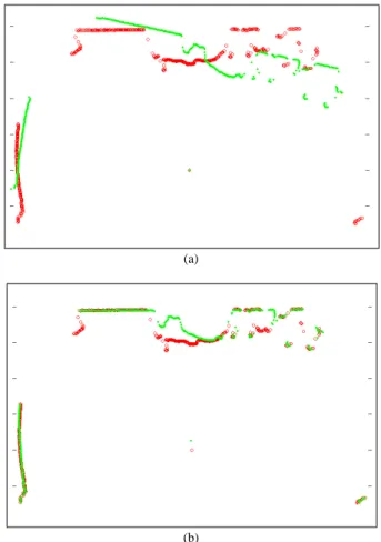
(a)
(b)
Figure 4: (a) Laser points from two consecutive scans. No-tice that although the two scans cover much of the same area of the environment, a rotational error creates substantial mis-alignment. (b) The resulting scans after scan-matching. Al-though some parts of the scans still do not align due to oc-clusion, sensor error or 3D effects, the majority of the points overlap.
5.2 EKF Data Fusion
The scan matcher outputs the estimated vehicle position
(x, y, θ), so to compute the full state estimate, including the
velocities, we use an EKF to fuse the scan matcher estimates with the acceleration readings from the IMU. This has several
scan matcher and their derivatives to control the vehicle. Al-though the IMU readings drift significantly and are therefore not useful over extended time periods, they are useful over short time periods, allowing us to improve our estimate of the vehicle’s velocities.
Our filter is a standard EKF, implemented using the open source KFilter library7. We use the filter to estimate the posi-tions, velocities, and accelerations of the vehicle, along with the biases in the IMU. By flying the helicopter with the state estimation process running in a motion capture system, we obtain ground-truth values with which to compare our state estimates.
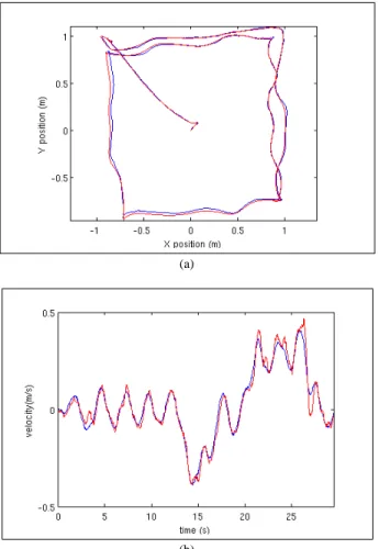
(a)
(b)
Figure 5: Comparison of the position (a) and velocity (b) es-timated by the onboard sensors (red) with ground truth mea-surements (blue).
Figures 5(a) and 5(b) demonstrate the quality of our EKF state estimates. We compared the EKF state estimates with ground-truth state estimates recorded by the motion capture system, and found that the estimates originating from the laser range scans match the ground-truth values closely in both position and velocity. Throughout the1min flight, the
average distance between the two position estimates was less 7KFilter.http://kalman.sourceforge.net
that1.5cm. The average velocity difference was 0.02m/s,
with a standard deviation of 0.025m/s. The vehicle was
not given any prior information of its environment (i.e., no map). However, since all the walls in the room were con-stantly within the laser’s field-of-view in this experiment, the SLAM module was not needed to eliminate drift.
5.3 SLAM
We made use of the publicly available implementation of the GMapping [23] algorithm that is available in the OpenSlam repository8, which performs SLAM in 2D. De-spite the fact that the helicopter operates in the full 3D en-vironment, the algorithm works surprisingly well and serves as a proof of concept for implementing SLAM on a MAV.
GMapping is an efficient Rao-Blackwellized particle fil-ter which learns grid maps from laser range data. We chose it due to its outstanding accuracy, real-time performance, and its ability to handle changes to the 2D map that occur due to changing height and attitude, as discussed in Section 3.3. While the algorithm worked reasonably well out of the box, we made modifications that improved its performance when used in 3D environments on a MAV. The motion model for the particles in the GMapping algorithm was based on a stan-dard motion model for ground robots with wheel odometry. However, since we use estimates computed by the laser scan matching module, we modified GMapping’s motion model to propagate the particles using the uncertainties computed by the scan-matching module.
In addition to the motion model, we modified the map rep-resentation so that the map gets updated rapidly in response to changes in height. The algorithm computes the probability that each grid cell is occupied or free based on the number of times a laser beam reflects off, or passes through, the cell. If a particular cell has been hit many times, the algorithm places a very high confidence that the cell is occupied. However, if the helicopter changes heights, and the cell becomes part of free space, this confidence is no longer warranted. Unfortunately the laser must pass through the cell at least as many times as it was hit before the algorithm will be convinced that the cell is actually now free, resulting in a very slow adaptation of the map. Hence, we modified the map representation to cap the maximum confidence for each grid cell, allowing it to change from occluded to free (and vice-versa) more rapidly.
With these modifications, we are able to create large scale maps of the environment such as those shown in Section 6. The algorithm usually takes 1 to 2 seconds to process
in-coming laser scans, allowing it to be run online, but is not suitable to be directly incorporated into the real-time control loop. Instead, the GMapping algorithm periodically sends po-sition corrections to the data fusion EKF. Since the popo-sition corrections are delayed significantly from when the measure-ment upon which they were based was published, we must account for this delay when we incorporate the correction.
This is done by retroactively modifying the appropriate po-sition in the state history. All future state estimates are then recomputed from this corrected position, resulting in globally consistent state estimates. By incorporating the SLAM cor-rections after the fact, we allow the state estimates to be pro-cessed and published with low enough delay to control the MAV, while still incorporating the information from SLAM to ensure drift-free position estimates.
5.4 Planning and Exploration
In addition to computing globally consistent state esti-mates, the map generated by the SLAM algorithm is used to plan actions for the vehicle autonomously. Full autonomy requires a high-level planner that enables the MAV to explore environments without any human intervention. While explo-ration has been well-researched in ground robotics, differ-ences between air and ground vehicles, as discussed in Sec-tion 3, require different consideraSec-tions when deciding where to go next. In particular, the need to constantly provide con-trol signals to the MAV means that while we seek to explore the environment, we must also ensure that the MAV always remains well-localized.
Our algorithm trades off the speed with which the heli-copter completes coverage of the environment with safety, en-suring that there are known environmental features within the helicopter sensor’s field-of-view as it uncovers unexplored environments. We use a modified definition of frontiers, first proposed in [24], to choose possible positions in free space where the MAV should fly to next such that it can make ob-servations of previously unexplored regions in the environ-ment. In [24], free cells that are adjacent to unknown cells are grouped into frontier regions as possible goals for the robot. We use a similar method to [24] to identify frontier regions, however, for each of these frontier regions, we seek to find a frontier pose that maximizes both the amount of unexplored space that is expected to be observed and the ability of the MAV to localize itself, which we define below.
The first step in our exploration algorithm is to identify candidate frontier regions. Frontier regions are areas in the map where there is a direct transition between free and un-explored cells. Since the walls in occupancy maps such as those generated by GMapping may have small gaps, the set of regions is then filtered to remove spurious frontiers. The algorithm must then identify the pose within these frontier regions that provides the best tradeoff between localization ability, and uncovered area. Searching over all poses in the frontier regions is too slow to allow the algorithm to run on-line, so frontier poses are sampled in each region. For each sample, two metrics are used to calculate a weight associ-ated with each sample. First, the amount of unexplored space that the MAV will observe can be estimated by simulating the laser sensor data that the MAV is expected to obtain at the sampled pose, given the latest map. By extracting the
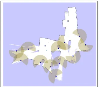
Figure 6: The blue pointers indicate frontiers that allow the MAV to explore and self-localize simultaneously. The laser’s field-of-view at those frontiers is drawn in brown. Notice that at the edges of free space, the chosen frontiers position the ve-hicle such that the expected laser scan spans both unexplored regions for exploration and unique obstacles for localization.
currently unexplored and dividing by the maximum number of grid cells covered by a laser range scan, we get a normal-ized weight,IU R(x) in the range of [0, 1] for the amount of unexplored information that the MAV is expected to observe. Using this metric alone will result in frontier points that are at the extreme borders of the map facing the unexplored region, since such a pose will maximize the number of grid cells in the laser’s field-of-view that are unexplored. Unfor-tunately, this pose provides no guarantees that the MAV will be able to localize itself, since the unknown environment may not contain enough structure for the relative position estima-tion algorithms to match against. In the extreme case, the MAV could be facing an open space where the nearest walls are beyond the maximum range of the laser scanner, giving the MAV no information with which to localize itself.
We therefore add an additional “Sensor Uncertainty” met-ric, first coined in [25]. Sensor uncertainty is used to quantify the MAV’s ability to localize itself at different positions in the map. A sensor uncertainty field maps locationsx in the map
to expected information gain, x → ISU(x), by calculating the difference in entropy of the prior and posterior distribu-tion ISU(x) = H(p(x)) − H(p(x|z)) (3) where entropy is H(p(x)) = − Z p(x) log p(x)dx (4)
a constant priorp(x) = Σ0such thatH(p(x)) = C, as well as Bayes’ rule to computep(x|z) = p(z|x) · p(x), such that
ISU(x) = C − H(p(z|x))Σ0 (5)
We compute the entropy ofp(z|x) by deterministically
ex-tracting a set of sigma points [26], or samples along the main axes of the current covariance estimate, and observing how they are transformed when they are passed through the mea-surement function. For each sample, we simulate the sensor measurements and find the probability of observing the sen-sor measurement at each of the sigma points. The lower the probability of observation at the neighboring sigma points, the smaller the entropy of the posterior distribution, and there-fore the greater the information gain. Locations with high in-formation gain correspond to locations that generate sensor measurements that we expect to maximize the localization accuracy of the vehicle. After normalizing this with the prior entropy,ISU(x) is also a weight that lies in the range of [0, 1]. Using these two weights, we are able to find frontiers that maximize both the exploration and localization capabilities of the MAV. In each frontier region, we sample a set of can-didate poses, and accept as the goal point for that region, the sample that maximizes the weighted sum of the two informa-tion metrics, such thatI(x) = IU R(x) + ISU(x). Figure 6 shows the frontier points generated accordingly, where points are chosen such that the expected laser scan will both uncover unexplored regions and observe known obstacles, enabling the MAV to simultaneously explore and localize.
To achieve autonomous exploration of an unknown envi-ronment, the planner uses the nearest frontier as its goal and computes a path using the dynamic programming-based path planner in the CARMEN robot navigation toolkit. The fron-tier extraction modules run fast enough that they are able to re-generate plans as the vehicle moves through the environ-ment and as the map is updated.
6 EXPERIMENTS ANDRESULTS
We integrated the suite of technologies described above to perform autonomous navigation and exploration in un-structured and unknown indoor environments. In this section, we present results demonstrating that the sys-tem is capable of fully autonomous operation in a va-riety of indoor environments. To get a full picture of our system in action, we suggest that the reader also view the videos taken of these experiments available at:
http://groups.csail.mit.edu/rrg/videos.html.
6.1 Autonomous navigation in open lobbies
We flew the vehicle across the first floor of MIT’s Stata Center. The vehicle was not given a prior map of the environ-ment, and flew autonomously using only sensors onboard the helicopter. In this experiment, the vehicle was guided by a human operator clicking high-level goals in the map that was being built in real-time, after which the planner planned the
best path to the goal. The vehicle was able to localize itself and fly stably throughout the environment. Figure 7(a) shows the final map generated by the SLAM algorithm at the end of the experiment. During the8min flight until the battery was
exhausted, the vehicle flew a distance of208.6m.
6.2 Autonomous navigation in cluttered environments
While unstructured, the lack of clutter along the walls in the lobby environment allowed the 2D map assumption to hold fairly well. We next tested our system by flying through a cluttered lab space (Figure 2, insert of Figure 7(b)), operat-ing close to the ground. At this height, chairs, desks, robots, plants, and other objects in the area caused the 2D cross-sectional scan obtained by the laser rangefinder to vary dra-matically with changes in height, pitch, and roll. The resul-tant SLAM map of the environment is shown in Figure 7(b). The grey features littered within the otherwise free space de-note the objects that clutter the environment and are occa-sionally sensed by the laser rangefinder. Despite the cluttered environment, our vehicle was able to localize itself and main-tain a stable flight for6min over a distance of 44.6m, a feat
that would not have been possible with a static map assump-tion.
6.3 Autonomous exploration in office hallways
Finally, to demonstrate fully autonomous operation of the vehicle, we closed the loop with our exploration algorithm, as discussed in Section 5.4. The helicopter was tasked to ex-plore the hallway environment shown in the insert of Figure 7(c). Once the helicopter took off and began exploring, we had no human control over the helicopter’s actions as it au-tonomously explored the unknown environment. The heli-copter continuously searched for and generated paths to ar-eas of new information. Figure 7(c) shows the map built from7min of autonomous flight, after traveling a distance of 75.8m.
7 CONCLUSION
In this work, we have developed a quadrotor helicopter that is capable of fully autonomous exploration in unstruc-tured and unknown indoor environments without a prior map, relying solely on sensors onboard the vehicle. By reasoning about the key differences between autonomous ground and air vehicles, we have created a suite of algorithms that accounts for the unique characteristics of air vehicles for estimation, control and planning. Having developed a helicopter plat-form that has many of the capabilities of autonomous ground robots, we believe that there is great potential for future ex-tensions of such platforms to operate in fully 3-dimensional environments.
ACKNOWLEDGMENTS
Abraham Bachrach was supported by the ARO MAST CTA, Ruijie He was supported by the Republic of Singapore
(a) Map of MIT Stata Center, 1st Floor.
(b) Map of MIT Stata Center, 3rd Floor. (c) Map of MIT Stata Center, basement.
Figure 7: (a) Map of the first floor of MIT’s Stata center constructed by the vehicle during autonomous flight. (b) Map of a cluttered lab space with significant 3D structure. (c) Map of constrained office hallway generated under completely autonomous exploration. Blue circles indicate goal waypoints clicked by human operator. Red line indicates path traveled based on the vehicle’s estimates.
Armed Forces, and Nicholas Roy was supported by NSF Di-vision of Information and Intelligent Systems under grant # 0546467. The authors wish to thank the following people for their support in the project: Giorgio Grisetti, Cyrill Stach-niss and Wolfram Burgard provided the GMapping software
toolkit. Daniel Gurdan, Jan Stumpf and Markus Achtelik pro-vided the quadrotor helicopter and the support of Ascending Technologies. Edwin Olson for providing us with a reference implementation of his scan-matcher. Samuel Prentice and Garrett Hemann assisted with the development of the
hard-ware.
REFERENCES
[1] A. Bachrach, R. He, and N. Roy. Autonomous flight in unstructed and unknown indoor environments. In
Pro-ceedings of EMAV, 2009.
[2] A. Bachrach, A. Garamifard, D. Gurdan, R. He, S. Pren-tice, J. Stumpf, and N. Roy. Co-ordinated tracking and planning using air and ground vehicles. In Proc. ISER, 2008.
[3] S. Scherer, S. Singh, L. Chamberlain, and S. Saripalli. Flying Fast and Low Among Obstacles. In Proc. ICRA, pages 2023–2029, 2007.
[4] A. Coates, P. Abbeel, and A.Y. Ng. Learning for control from multiple demonstrations. In Proc. ICML, pages 144–151. ACM, 2008.
[5] T. Templeton, D.H. Shim, C. Geyer, and S.S. Sastry. Autonomous Vision-based Landing and Terrain Map-ping Using an MPC-controlled Unmanned Rotorcraft. In Proc. ICRA, pages 1349–1356, 2007.
[6] J.P. How, B. Bethke, A. Frank, D. Dale, and J. Vian. Real-time indoor autonomous vehicle test environment.
Control Systems Magazine, IEEE, 28(2):51–64, 2008.
[7] G.M. Hoffmann, H. Huang, S.L. Waslander, and C.J. Tomlin. Quadrotor helicopter flight dynamics and con-trol: Theory and experiment. In Proc. of GNC, Hilton Head, SC, August 2007.
[8] J.F. Roberts, T. Stirling, J.C. Zufferey, and D. Floreano. Quadrotor Using Minimal Sensing For Autonomous In-door Flight. In Proc. EMAV, 2007.
[9] S. Bouabdallah, P. Murrieri, and R. Siegwart. Towards autonomous indoor micro vtol. Autonomous Robots, Vol. 18, No. 2, March 2005.
[10] G.P. Tournier, M. Valenti, J.P. How, and E. Feron. Esti-mation and control of a quadrotor vehicle using monoc-ular vision and moir`e patterns. In Proc. of AIAA GNC,
Keystone, Colorado, 2006.
[11] N.G. Johnson. Vision-assisted control of a hovering air vehicle in an indoor setting. Master’s thesis, BYU, 2008.
[12] C. Kemp. Visual Control of a Miniature Quad-Rotor
Helicopter. PhD thesis, Churchill College, University
of Cambridge, 2006.
[13] S. Ahrens, D. Levine, G. Andrews, and J.P. How. Vision-based guidance and control of a hovering vehi-cle in unknown, gps-denied environments. In Robotics
and Automation, 2009. ICRA ’09. IEEE International Conference on, pages 2643–2648, May 2009.
[14] R. He, S. Prentice, and N. Roy. Planning in information space for a quadrotor helicopter in a gps-denied envi-ronments. In Proc. ICRA, 2008.
[15] G. Angeletti, J.R. P. Valente, L. Iocchi, and D. Nardi. Autonomous indoor hovering with a quadrotor. In
Work-shop Proc. SIMPAR, pages 472–481, 2008.
[16] S. Grzonka, G. Grisetti, and W. Burgard. Towards a nav-igation system for autonomous indoor flying. In Proc.
ICRA, 2009.
[17] S. Thrun, D. Fox, W. Burgard, and F. Dellaert. Robust monte carlo localization for mobile robots. Artificial
Intelligence, 128:99–141, 2000.
[18] A. Howard. Real-time stereo visual odometry for au-tonomous ground vehicles. In Proc. IROS, 2008. [19] Lingemann K., Nchter A., Hertzberg J., and
Sur-mann H. High-speed laser localization for mobile robots. Robotics and Autonomous Systems, 51(4):275– 296, June 2005.
[20] Edwin Olson. Robust and Efficient Robotic Mapping. PhD thesis, MIT, Cambridge, MA, USA, June 2008. [21] D. Gurdan, J. Stumpf, M. Achtelik, K.M. Doth,
G. Hirzinger, and D. Rus. Energy-efficient autonomous four-rotor flying robot controlled at 1 khz. In Proc.
ICRA, 2007.
[22] F. Lu and E. Milios. Globally consistent range scan alignment for environment mapping. Autonomous Robots, 4:333–349, 1997.
[23] G. Grisetti, C. Stachniss, and W. Burgard. Improved techniques for grid mapping with rao-blackwellized particle filters. IEEE Transactions on Robotics,
23(1):34–46, 2007.
[24] B. Yamauchi. A frontier-based approach for au-tonomous exploration. In Proc. CIRA, 1997.
[25] H. Takeda and J.C. Latombe. Sensory uncertainty field for mobile robot navigation. Proc. ICRA, 1992. [26] S.J. Julier, J.K. Uhlmann, and H.F. Durrant-Whyte.
A new approach for filtering nonlinear systems. In
Proceedings of the American Control Conference,