Publisher’s version / Version de l'éditeur:
Vous avez des questions? Nous pouvons vous aider. Pour communiquer directement avec un auteur, consultez la première page de la revue dans laquelle son article a été publié afin de trouver ses coordonnées. Si vous n’arrivez pas à les repérer, communiquez avec nous à PublicationsArchive-ArchivesPublications@nrc-cnrc.gc.ca.
Questions? Contact the NRC Publications Archive team at
PublicationsArchive-ArchivesPublications@nrc-cnrc.gc.ca. If you wish to email the authors directly, please see the first page of the publication for their contact information.
https://publications-cnrc.canada.ca/fra/droits
L’accès à ce site Web et l’utilisation de son contenu sont assujettis aux conditions présentées dans le site LISEZ CES CONDITIONS ATTENTIVEMENT AVANT D’UTILISER CE SITE WEB.
1st Canadian Conference on Effective Design of Structures [Proceedings], pp. 187-196, 2005-07-10
READ THESE TERMS AND CONDITIONS CAREFULLY BEFORE USING THIS WEBSITE.
https://nrc-publications.canada.ca/eng/copyright
NRC Publications Archive Record / Notice des Archives des publications du CNRC :
https://nrc-publications.canada.ca/eng/view/object/?id=77b1f004-99c6-40bc-b7ff-36a70518f1fd https://publications-cnrc.canada.ca/fra/voir/objet/?id=77b1f004-99c6-40bc-b7ff-36a70518f1fd
NRC Publications Archive
Archives des publications du CNRC
This publication could be one of several versions: author’s original, accepted manuscript or the publisher’s version. / La version de cette publication peut être l’une des suivantes : la version prépublication de l’auteur, la version acceptée du manuscrit ou la version de l’éditeur.
Access and use of this website and the material on it are subject to the Terms and Conditions set forth at
Finite element model for predicting corrosion-induced cracking, spalling and delamination of RC bridge decks
Finite element analysis of corrosion-induced cracking, spalling and delamination of RC bridge
decks
Zhou, K.; Martin-Pérez, B.; Lounis, Z.
NRCC-48147
A version of this document is published in / Une version de ce document se trouve dans : 1st Canadian Conference on Effective Design of Strucutres, Hamilton, Ont.,
July 10-13, 2005, pp. 187-196
1st Canadian Conference on Effective Design of Structures McMaster University
Hamilton, Ontario, Canada July 10 – 13, 2005
Finite Element Analysis of Corrosion-Induced Cracking, Spalling and
Delamination of RC Bridge Decks
K. Zhou1, B. Martín-Pérez2 and Z. Lounis3
1
Graduate Student, Dept. of Civil Engineering, University of Ottawa, Ottawa, ON, K1N 6N5, Canada, zhk19@hotmail.com
2
Assistant Professor, Dept of Civil Engineering, University of Ottawa, Ottawa, ON, K1N 6N5, Canada, bmartin@eng.uottawa.ca
3
Research Officer, Institute for Research in Construction, National Research Council, Ottawa, ON K1A 0R6, Canada, zoubir.lounis@nrc.ca
Abstract
The corrosion of reinforcing steel in reinforced concrete (RC) bridge decks due to the application of de-icing salts in winter has been recognized as one of the major causes of highway bridge deterioration in North America. Corrosion-induced damage is usually manifested by longitudinal cracking, spalling, and/or delamination of the concrete cover due to the expansion of corrosion products accumulating around the reinforcement. This damage leads to reduction or loss of serviceability, safety, and service life of RC bridge decks. This paper presents finite element analyses of the behaviour of the concrete bridge deck cover subjected to reinforcing steel corrosion. The prediction of the damage caused by corroding reinforcing bars is established by calculating the induced stresses in the surrounding concrete. The numerical model is used to conduct a parametric investigation of several design variables. It is found from the analyses that different failure mechanisms govern depending on the geometry and configuration of the reinforcing bars in the concrete cover of the bridge deck. Finally, the impact of concrete overlays on the governing failure modes of cracking, spalling and/or delamination of the concrete cover is investigated by using the model.
Keywords: reinforcement corrosion, longitudinal cracking, spalling, delamination, finite elements.
Introduction
Corrosion of reinforcing steel due to the application of de-icing salts in the wintertime is the leading cause of deterioration of RC bridge decks in North America. The damage induced by the
expansion of corrosion products deposited on the reinforcement is accumulated in the form of cracking, spalling and/or delamination of the concrete cover. If left unattended, this damage can impair the serviceability, safety and service life of affected RC bridge decks.
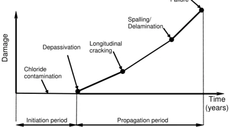
Most of the published service life models associated with corrosion of reinforcing steel in concrete have followed a simplified model that was first introduced by Tuutti1, wherein the mechanism of corrosion is considered as a two-stage process: (i) an initiation period, during which chlorides penetrate the concrete cover in sufficient quantities until the reinforcing steel is depassivated, and (ii) a propagation period, during which the structure deteriorates as a result of loss of reinforcing steel cross-sectional area and accumulation of corrosion products around the bar surface. This second phase lasts until an unacceptable degree of corrosion damage has occurred. Accumulation of corrosion-induced damage induces longitudinal cracking, spalling, and/or delamination of the concrete cover, and ultimately failure or total loss of serviceability/functionality (see Figure 1).
Da ma ge Depassivation Longitudinal cracking Failure Time (years) Propagation period Spalling/ Delamination Initiation period Chloride contamination
Figure 1 – Corrosion-induced damage of RC structures
During the last two decades, considerable research has been carried out to understand and quantify the chloride contamination and onset of corrosion corresponding to the initiation period in Tuutti’s model. However, less effort has been devoted to modelling the mechanical effect of reinforcing steel corrosion and its impact on serviceability and safety of RC structures2-5. This is due to the difficulty in quantifying the propagation stage, as a result of its dependence on several factors that have considerable uncertainty, such as the onset of steel depassivation, the rate and geometry of corrosion build-up, and the type of corrosion products formed. This paper explores the effect of corrosion-induced damage in RC bridge decks through finite element modelling of the associated mechanical problem. The numerical model is used to conduct a parametric investigation of several design variables that govern the level of corrosion-induced damage.
Finite element model
Corrosion-induced damage of RC bridge decks was investigated using the commercial finite element package ABAQUS/Standard6. The damage caused by corroding reinforcing bars was predicted by analyzing the state of stress induced in the surrounding concrete. The following assumptions were made in the analysis: (1) the concrete deck was modelled in a state of plane
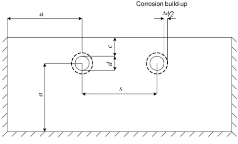
strain (εz = 0), which corresponds to stress conditions associated with a splitting mode of failure; (2) the geometry of the corrosion products was assumed to be a uniform build-up around the surface of the rebar; and, (3) the concrete material properties were assumed to be time-independent. Based on these assumptions, the accumulation of corrosion products on the rebars was simulated by imposing a uniform radial displacement along the surface of the reinforcing bar (Δd/2 in Figure 2), which was applied in small equal increments. The total radial corrosion build-up imposed on the surface of the reinforcing bars was Δd/ 2=0.2mm, which was divided into 400 equal incremental steps; at each step, the radial corrosion build-up was
mm (Δd/ 2) / 400=0.0005 2,3.
Design variables defining the geometry of the problem are the concrete cover c, the rebar diameter d, and the rebars spacing s (see Figure 2). Since the area of interest is that of the concrete surrounding the corroding rebars (concrete cover), only that area was discretized in the finite element model. The concrete cover was truncated at a distance a from the centre of the rebars, where fixed boundaries were imposed. A sensitivity analysis was carried out to ensure that the results were independent of the location of these boundaries. From the results, distance a was chosen as a ≥ 3c, where c ranged between 1.5d and 6d.
To simulate the initiation and propagation of cracks in the RC deck subjected to different levels of corrosion build-up, a damaged plasticity model from ABAQUS/Standard6 material library was used. The damaged plasticity model uses the tensile equivalent plastic strain to define concrete cracking. The tensile equivalent plastic strain rate is equal to a nonzero weight factor times the maximum plastic strain rate. If the maximum plastic strain is positive, concrete cracking is assumed to initiate. The direction of the vector normal to the crack plane is assumed to be parallel to the direction of the maximum principal plastic strain. A 4-node first-order element with reduced integration (CPE4R6) was used in the analyses.
a a c d s Corrosion build-up d Δ/2
Figure 2 – Geometry of RC bridge deck model Modelling unprotected RC decks
Based on the finite element model previously described, the different failure mechanisms of the RC bridge deck caused by the corrosion build-up on the reinforcing bars for different concrete cover geometries and rebar configurations were analyzed. The bridge deck was assumed to be
undamaged, and its material properties were taken as: uniaxial compressive strength f’c = 30 MPa, Poisson’s ratio ν = 0.2, tensile strength f’t = 1.8 MPa, and modulus of elasticity Ec = 26,000 MPa.
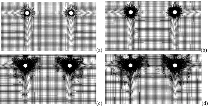
Depending on the level of corrosion build-up Δd/2 and the values of c, d, and s, different failure patterns were observed: (i) cracking initiation at the concrete/steel interface; (ii) longitudinal cracking on the surface along the reinforcement; (iii) spalling of the concrete cover; and, (iv) delamination of the concrete cover. The cracking patterns and the corresponding levels of radial corrosion build-up for c = 35 mm, d = 16 mm, s = 173 mm, and a = 150 mm are illustrated in Figure 3.
(a) (b)
(c) (d)
Figure 3 – Corrosion-induced failure modes, (a) Cracking initiation (Δd/2 = 0.001 mm), (b) Longitudinal cracking (Δd/2 = 0.008 mm), (c) Spalling (Δd/2 = 0.079 mm), (d) Delamination
(Δd/2 = 0.0825 mm)
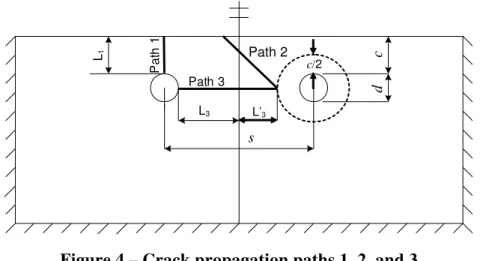
From the analyses, it was found that cracks propagated along the radial direction after initiation of cracking at the steel/concrete interface. However, when cracks reached almost half depth of the deck cover, cracks continued to propagate along three main directions depending on the geometry configuration: the vertical direction, the horizontal direction, and the 45°-direction measured from the horizontal, which respectively correspond to paths 1, 3 and 2 in Figure 4. Longitudinal cracking occurred when cracks developed along path 1 and reached the surface of the concrete cover. Delamination of the concrete cover occurred when two cracks initiated from the neighbouring reinforcing bars’ surface and propagated along path 3 towards each other. Spalling of the concrete cover occurred when cracks developed along path 2 and reached the surface of the bridge deck.
In general, the observed damage of the RC bridge deck was a combination of two failure patterns. Depending on the value of the rebar spacing s, the following failure modes were observed: (1) delamination followed by longitudinal cracking; (2) longitudinal cracking followed by delamination; and, (3) longitudinal cracking followed by spalling. The actual values of s that
led to the different failure modes depended on the actual concrete cover-to-rebar diameter ratio
c/d and the rebar spacing-to-rebar diameter ratio s/d. Whether failure mode (1) governed over failure mode (2) depended on the lengths of paths 1 and 3, L1 = c and L3 =
(
s−d)
2, respectively, as illustrated in Figure 4. The limiting criterion of s between these two failure modes (i.e., longitudinal cracking or delamination) was obtained by setting L1 = L3, i.e.,(
)
1 3 2 or 2
L ≤L ⇒ c≤ s−d s≥ c+d (1)
For rebar spacing s greater than or equal to2c+d, longitudinal cracking occurred before delamination. On the other hand, for rebar spacing s lower than2c+d, delamination occurred before longitudinal cracking.
c d s L1 L3 Pa th 1 Path 3 Path 2 c/2 L’3
Figure 4 – Crack propagation paths 1, 2, and 3
In general, spalling of the concrete cover occurred after delamination had taken place. However, if the spacing between reinforcing bars reached a large value, spalling would occur before delamination. The limiting criterion for s that differentiated between spalling or delamination as the governing failure mode was also determined by the lengths of paths 2 and 3’,
(
)
2 2 2
L = c+d and L3′ = − +⎡⎣s
(
c d)
⎤⎦ 2d
, in Figure 4.
Spalling of the concrete cover occurred when length L2 was smaller than L’3 (cracks will always propagate along the shortest distance.) The limiting criterion between these two failure modes was obtained from:
2 3 0.261 0.631 or 3.828 2.414
L ≤L′ ⇒ c≤ s− d s≥ c+ d (2)
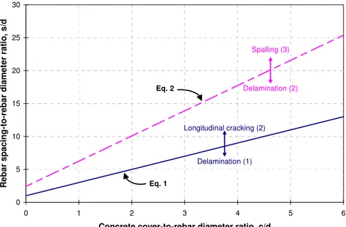
For spacing between reinforcing bars s greater or equal to 3.828c+2.414 , spalling occurred before delamination. On the contrary, for rebar spacing s lower than 3.828c+2.414d, delamination occurred before spalling. The two limiting criteria between different failure modes (Eqs. 1 and 2) as a function of c/d and s/d are illustrated in Figure 5. This figure shows the regions in which each failure mechanism governs: (1) delamination followed by longitudinal cracking; (2) longitudinal cracking followed by delamination; and, (3) longitudinal cracking followed by spalling of the cover. Note that in region (1) delamination will always occur first, whereas in regions (2) and (3) longitudinal cracking will occur first.
0 5 10 15 20 25 30 0 1 2 3 4 5 6
Concrete cover-to-rebar diameter ratio, c/d
Re bar spac ing-t o -re b ar d iam eter ratio , s/d Longitudinal cracking (2) Delamination (1) Spalling (3) Delamination (2) Eq. 1 Eq. 2
Figure 5 – Limiting criteria between governing corrosion-induced failure modes of the bridge deck concrete cover
Parametric analysis
Given the uncertainty associated with the governing variables, a parametric study was conducted to investigate the influence of the uniaxial compressive strength of concrete f’c, the ratio of the clear cover of the RC bridge deck to the diameter of the rebar c/d, and the spacing between rebars s on the amount of corrosion build-up to cause cracking initiation, longitudinal cracking, spalling and delamination of the unprotected concrete deck cover. Table 1 shows the range of values used in the parametric analysis for each variable.
Table 1: Range of values used in parametric analysis
f’c (MPa) c (mm) d (mm) s (mm)
20, 25, 30 35, 50, 65 11, 16, 20, 25 80–300
From the results, it was found that the value of the level of corrosion build-up causing cracking initiation at the steel/concrete interface was not affected by changing the ratio c/d; however, this value increased slightly with the increase of f’c. Cracking initiation at the steel/concrete interface depends more on the material properties of the concrete cover than on its geometric configuration. On the other hand, the limiting criteria to determine the other failure mechanisms (longitudinal cracking, spalling, and delamination) only depended on the values of
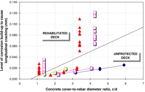
c, d, and s (as set by Eqs. 1 and 2) and were independent of the strength of the bridge deck cover. As previously described, the corrosion-induced failure mechanisms simulated by the finite element model were very sensitive to the lengths of the paths through which cracks developed. Therefore, the values of the level of corrosion build-up causing longitudinal cracking were expected to be affected by the length of path 1 in Figure 4, i.e., L1= . From the results, it was c
found that the level of corrosion build-up Δd/2 to cause longitudinal cracking increased as c/d increased (see Figure 6). If c/d was unchanged, a higher value of d would lead to higher values of
Δd/2. This is due to the fact that when d increases and c/d remains unchanged, the value of c increases, i.e., the length of path 1 in Figure 4 also increases, resulting in an increasing value of Δd/2. 0.000 0.020 0.040 0.060 0.080 0.100 0.120 0.140 0 1 2 3 4 5 6 7
Concrete cover-to-rebar diameter ratio, c/d
Le vel of cor ros ion bui ld-u p to ca use longitudina l cr ack ing (mm ) d = 11 mm d = 16 mm d = 20 mm d = 25 mm UNPROTECTED DECK REHABILITATED DECK
Figure 6 – Influence of c/d on the level of corrosion build-up causing longitudinal cracking for different rebar diameters
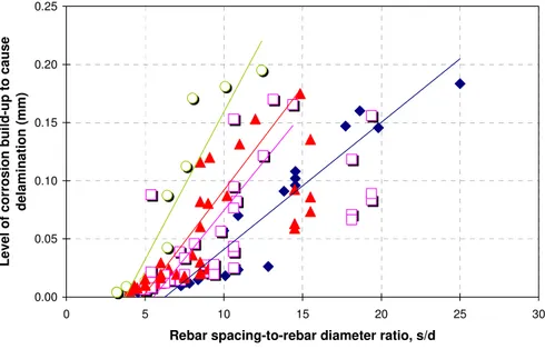
The values of corrosion build-up causing delamination are affected by the length of path 3 in Figure 4, i.e., L3 = −
(
s d)
2. This length is not only affected by the value of the rebar diameter d but also by the value of rebar spacing s. From the finite element analyses, it was found that the Δd/2 causing delamination decreased as d increased when s was fixed, since the length of path 3 decreased too. However, when d and s remained unchanged, the value of c/d had no impact on the onset of delamination of the bridge deck cover. It was also found that the level of corrosion build-up causing delamination increased as s increased when c and d remained unchanged, since(
)
3 2
L = −s d increased too. The main parameter thus influencing delamination of the concrete cover is the spacing between reinforcing bars s, as illustrated in Figure 7.
The values of corrosion build-up causing spalling depend on the length of path 2 in Figure 4, i.e., L2 = 2
(
c+d 2 . Therefore, spalling of the concrete cover is influenced by the values taken)
by c and d. The analyses revealed that Δd/2 causing spalling increased as c/d increased. If the concrete cover-to-rebar diameter ratio c/d was fixed, a higher value of d led to a higher value of Δd/2. This was due to the fact that when d increases and c/d remains constant, L2 = 2(
c+d 2)
increases, resulting in an increasing value for Δd/2. The influence of c/don the level of corrosion build-up causing spalling is shown in Figure 8.0.00 0.05 0.10 0.15 0.20 0.25 0 5 10 15 20 25 30
Rebar spacing-to-rebar diameter ratio, s/d
Le vel of cor ros ion bui ld-u p to ca use del a mi nat ion (mm ) d = 11 mm d = 16 mm d = 20 mm d = 25 mm
Figure 7 – Influence of s/d on the level of corrosion build-up causing delamination for different rebar diameters
0.00 0.02 0.04 0.06 0.08 0.10 0.12 0.14 0.16 0.18 0.20 0 1 2 3 4 5 6 7
Concrete cover-to-rebar diameter, c/d
Leve l of corrosi on b u ild -up to c a us e s p al ling (mm ) d = 11 mm d = 16 mm d = 20 mm d = 25 mm
Figure 8 – Influence of c/d on the level of corrosion build-up causing spalling for different rebar diameters
Modelling rehabilitated RC decks
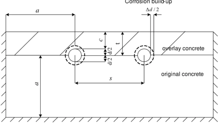
The effect of rehabilitating an RC bridge deck with an overlay on the corrosion-induced damage of the concrete cover was also studied through the use of the finite element model previously presented. In the analyses, it was assumed that after corrosion-induced damage occurred, the damaged cover of the RC bridge deck was removed and overlaid with a new material. The
geometry configuration of the finite element model is shown in Figure 9, where t denotes the overlay thickness (t= +c d 2). a a c s Corrosion build-up / 2 d Δ d/ 2 d/ 2 original concrete overlay concrete t
Figure 9 – Geometry configuration of the rehabilitated RC bridge deck
Two types of overlay materials were used in the analyses: micro-silica concrete (MSC) overlay and latex-modified concrete (LMC) overlay. Properties for these overlays are tabulated in Table 2.
Table 2: Properties of overlays7,8
Type of overlay Thickness, t (mm) f’c (MPa) E (MPa)
MSC 30–76 52–90 2.8×10⁴
LMC 30–76 40 1.7×10⁴
It was assumed in the finite element analysis that the overlay materials behave as linear elastic under uniaxial compression until the compressive stress reaches 75% of f’c and that the ultimate plastic strain is 0.0001. It was found from the analysis that the results were not sensitive to these values, because the maximum principal compressive stress obtained at the last time step was approximately 40% to 60% of f’c. In most cases, the maximum biaxial stresses of the finite elements could not reach the compression yield surface. The uniaxial tensile strength f’t of MSC and LMC was taken as that reported for high-performance concrete9, i.e., ft′=0.59 f ′c (MPa). Furthermore, perfect bond between the overlay and the substrate concrete was assumed in the finite element analyses.
From the analyses, it was found that after the onset of cracking, cracks propagated along two main directions: the vertical and horizontal directions, which respectively corresponded to paths 1 and 3 (similar as in Figure 4.) Longitudinal cracking occurred when cracks developed along path 1 and reached the surface of the deck. Delamination occurred when two cracks that initiated from neighbouring reinforcing bars developed along path 3 towards each other. Whereas path 1 was in the overlay, path 3 corresponded to the contact surface between the overlay and the substrate concrete.
Depending on the value of the spacing s between reinforcing bars, the failure modes of overlaid RC bridge decks due to corrosion build-up was classified as follows: (1) delamination
followed by longitudinal cracking, and (2) longitudinal cracking followed by delamination. When the spacing between rebars was very small, failure of the overlaid RC bridge deck was governed by delamination followed by longitudinal cracking. The values of corrosion build-up to cause delamination were similar to the unprotected deck (Figure 7). With the increase of the spacing between rebars, failure was governed by longitudinal cracking followed by delamination. The values of corrosion build-up to cause longitudinal cracking were much higher than in the unprotected deck (Figure 6). The limiting criterion between delamination and longitudinal cracking was similar to Eq. 1; however, it was observed that cracks propagated along path 3 at a much faster rate than along path 1. This is mainly due to the fact that the tensile strength of the overlay was higher than the original concrete, and that the contact interface between the two materials is a weak plane. Spalling of the concrete cover was not observed as a governing failure mode for an overlaid RC bridge deck.
Conclusions
This paper has presented a finite element model of the mechanical effect of reinforcing steel corrosion on RC bridge decks. It is found from the analyses that different failure modes (longitudinal cracking, spalling, and delamination) govern corrosion-induced damage depending on the geometry of the deck concrete cover and configuration of the reinforcing bars. Limiting criteria for the different failure patterns were established as a function of design variables of the concrete cover, namely concrete cover-to-rebar diameter ratio c/d and rebar spacing-to-rebar diameter ratio s/d. Whereas longitudinal cracking and spalling of the deck cover heavily depended on the value of c/d, delamination was determined by the spacing s between rebars. The impact of concrete overlays on the governing failure modes was also investigated by using the model, and it was found that overlaid RC bridge decks will fail by longitudinal cracking or delamination of the concrete cover rather than by spalling.
References
1. Tuutti, K., 1982, Corrosion of Steel in Concrete, Swedish Cement and Concrete Research Institute, Stockholm, Sweden, 469 pp.
2. Dagher, H. J., and Kulendran, S., 1992, Finite element modeling of corrosion damage in concrete structures, ACI Structural J., 89(6), 699-708.
3. Molina, F. J., Alonso, C., and Andrade, C., 1993, Cover cracking as a function of bar corrosion: part 2 - numerical model, Materials and Structures, 26, 532-548.
4. Weyers, R., 1998, Service life model for concrete structures in chloride laden environments, ACI Materials J., 95(4), 445–453.
5. Hansen, E.J., and Saouma, V.E., 1999, Numerical simulation of reinforced concrete deterioration: Part II – steel corrosion and concrete cracking, ACI Materials J., 96(3), 331-338. 6. Hibbit Karlsson & Sorensen Inc., 2004, ABAQUS/Standard User's Manual, Pawtucket, Rhode
Island.
7. ACI Committee 546, 1996, Concrete Repair Guide, ACI 546R-96, American Concrete Institute. 8. ACI Committee 548, 1994, Guide for Polymer Concrete Overlays, ACI 548.5R-94, American
Concrete Institute.
9. ACI Committee 363, 1992, State-of-the-Art Report on High-Strength Concrete, American Concrete Institute.